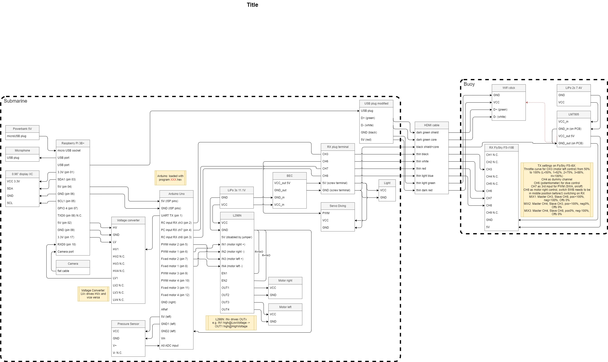
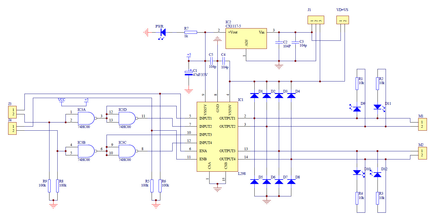
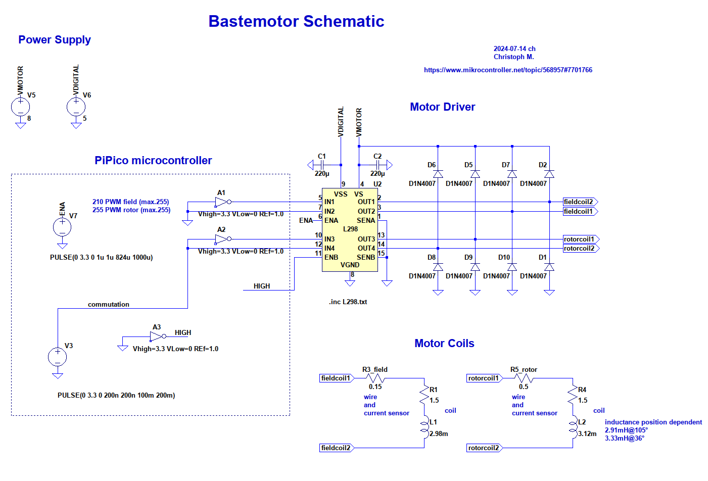
NUMBERS : L298L298HN (Multiwatt Horiz.) inductive loads such as relays, solenoids, DC and L298P (PowerSO20) stepping motors. Two enable inputs are provided to enableordisablethedeviceindependentlyofthein- put signals
: L29L298HN (Multiwatt Horiz.) inductive loads such as relays, solenoids, DC and L298P (PowerSO20) steppingmotors.Twoenableinputsareprovidedto enableordisablethedeviceindependentlyofthein- put signals.The emitters
NUMBERS : L298L298HN (Multiwatt Horiz.) inductive loads such as relays, solenoids, DC and L298P (PowerSO20) stepping motors. Two enable inputs are provided to enableordisablethedeviceindependentlyofthein- put signals
: L29L298HN (Multiwatt Horiz.) inductive loads such as relays, solenoids, DC and L298P (PowerSO20) steppingmotors.Twoenableinputsareprovidedto enableordisablethedeviceindependentlyofthein- put signals.The emitters
: L29L298HN (Multiwatt Horiz.) inductive loads such as relays, solenoids, DC and L298P (PowerSO20) steppingmotors.Twoenableinputsareprovidedto enableordisablethedeviceindependentlyofthein- put signals.The emitters
areavailable: theregular Figure 1 : Inthis typical configurationan L297 steppermotor controller and L298 dual bridgedriver com- bineto forma complete microprocessorto bipolar steppermotor interface. 1/18 AN470/0392 APPLICATION NOTE Forbipolarmotorswithwindingcurrentsupto2Athe THE L298N AND L293E L297should be used with the L298N ; for winding Sincethe L297 is normally used with an L298Nor currents up to 1Athe L293E is recommended (the L293E bridgedriver a briefreview of these devices L293will alsobeusefulif thechopperisn’tneeded
areavailable: theregular Figure 1 : Inthis typical configurationan L297 steppermotor controller and L298 dual bridgedriver com- bineto forma complete microprocessorto bipolar steppermotor interface. 1/18 AN470/0392 APPLICATION NOTE Forbipolarmotorswithwindingcurrentsupto2Athe THE L298N AND L293E L297should be used with the L298N ; for winding Sincethe L297 is normally used with an L298Nor currents up to 1Athe L293E is recommended (the L293E bridgedriver a briefreview of these devices L293will alsobeusefulif thechopperisn’tneeded
transistors. High density is one of the key features of the technology so the L297 die is very compact. THE L298N AND L293E Since the L297 is normally used with an L298N or L293E bridge driver a brief review of these devices will make the rest of this note easier to follow. The L298N and L293E contain two bridge
Handson Technology User Guide L298N Dual H-Bridge Motor Driver This dual bidirectional motor driver, is based on the very popular L298 Dual H-Bridge Motor Driver Integrated Circuit. The circuit will allow you to easily and independently
. The drivers like the L298N or L6202. To drive such a L297 implements enable chopping or one phase motor the center tap of the motor should be left chopping, selected by the control input. The unconnected and the two ends of
werden, b) oder mit Spezial-Treiber-ICs wie dem erwähnten L298, der bereits 2 integrierte Brückenschaltungen für einen Schrittnmotor mit 2 Motorwicklungen enthält, A B U+ C D L298 T1 T3 T1 T3 & & & & T2 T4 T2 T4 1 & & & & R 3 2 R sense sense EN24 EN1 GND GND daneben gibt es aber auch noch andere: L298 L 2619 → 2 H.Brücken BPL 377 LM18245 → 1 H-Brücke (Verwendet man nur die ‘unteren’ Transistoren einer H-Brücke, läßt sich mit ICs wie dem L298 auch ein unipolarer Schrittmotor betreiben: U+
besonders kompakter Platine! Nähere Informationen über Schrittmotoren als auch diese bewährte L297 / L298 Schaltung findet man u.a. im Wissensportal RN-Wissen unter: http://www.roboternetz.de/wissen/index.php/Schrittmotoren Die Schaltung wird ausschließlich über Takt- und Richtungssignale gesteuert. Die
gedreht aufstecken. Vor der Montage des Kühlkörpers empfiehlt es sich, die Auflageflächen von den L298 und dem MODE: Oberer Jumper: Phase-Chopping (default) oder Enable-Chopping. Beeinflußt die Art der BD135 dünn(!!!) mit Wärmeleitpaste bestreichen, um die Wärmeabfuhr zu verbessern. Stromregelung. Die
gedreht aufstecken. Vor der Montage des Kühlkörpers empfiehlt es sich, die Auflageflächen von den L298 und dem MODE: Oberer Jumper: Phase-Chopping (default) oder Enable-Chopping. Beeinflußt die Art der BD135 dünn(!!!) mit Wärmeleitpaste bestreichen, um die Wärmeabfuhr zu verbessern. Stromregelung. Die
tosenseand controlthe currentin steppingmotors and similar devices.Whenusedin conjunctionwith the L293, L298, L7150, L6114/L6115,the chip set forms a constantcurrent drive for an inductiveload andperformsalltheinterfacefunctionfromthecon- trollogic thru the powerstage. DIP18 SO20 Two or more devices may be
Controllerboard. Die Steuerung ist sehr einfach, nahezu identisch mit der Ansteuerung der beliebten Motorchips L298 oder L293D. Die Geschwindigkeit ist über einem PWM-Port, der bis zu 20 Khz liefern darf, regelbar. Weitere 2 Eingänge bestimmen die Drehrichtung oder Motorbremsung. Der Anschluss erfolgt über 10 poligen
atwhich conditions. of the translatorcircuit to form the6 controlsignals supplied to the power bridge (L298). More phasecurrent means more motor torque,but also higherenergyconsumption. When activated, bythe oscillator, the currentin the winding will raise, following the L/R time constant An analysisof the
driven in half step, normal and wawe drive modes and on-chip PWM chopper circuits permit switch- the L298N or L293E, or with discrete transistors mode control of the current in the windings. A and darlingtons. ABSOLUTE MAXIMUM RATINGS Symbol Parameter Value Unit V Supply voltage 10 V s Vi Input signals
10 GND SEN_A 10 GND 11 GND SEN_B 19 11 GND SEN_B 19 20 GND 7 7 7 7 20 GND 7 7 7 7 0 0 0 0 0 0 0 0 L298P013TR 1 F 1 F 1 F 1 F L298P013TR 5 F 6 F 7 F 8 F D UD UD UD U D UD UD UD U 0V 0V 0V 0V 0V 0V 0V 0V 0V 0V R24 R11 470k 470k 18k MOTOR_B_I1/1.8C R5 10 IC2C MOTOR_A_I1/1.8B 3 IC2A 18k 8 MOTOR_B_CS1 R1
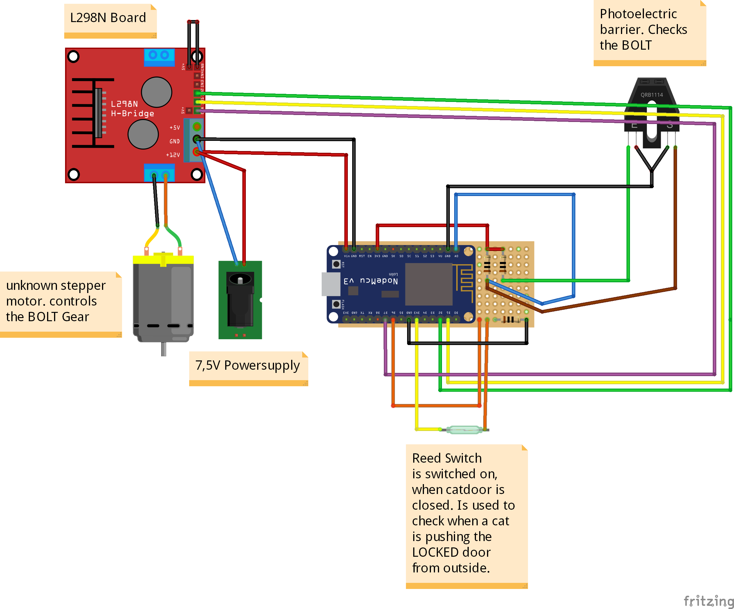
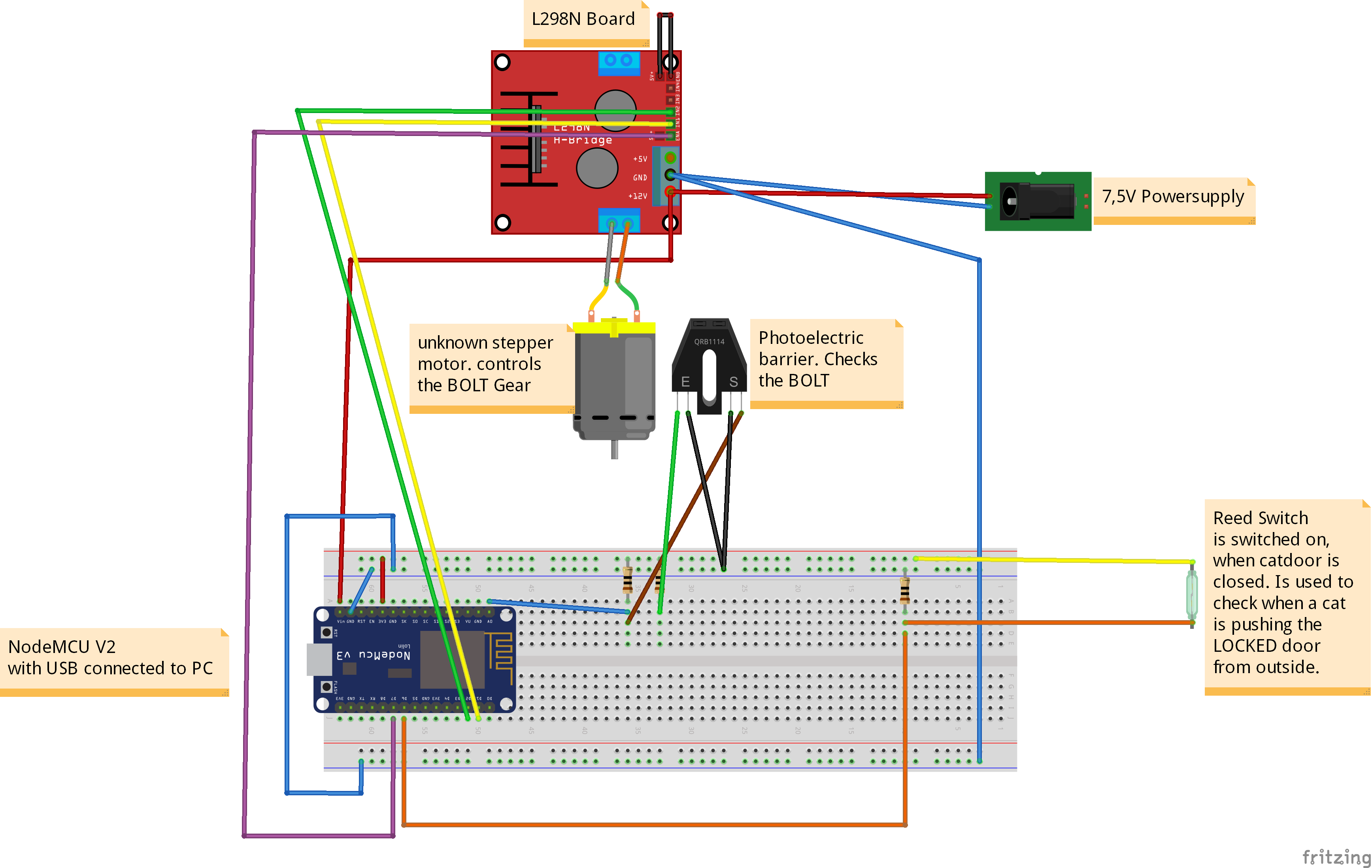
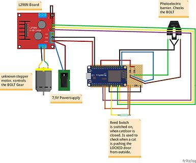
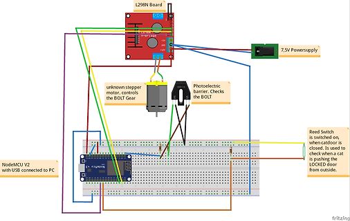
L298N Board, +5V, GND, +12V, 7,5V Powersupply, unknown stepper motor. controls the BOLT Gear, Photoelectric barrier. Checks the BOLT, E, S, Reed Switch is switched on, when catdoor is closed. Is used to
Sinussignale vom Adc –Ausgang meines uC? Oder nur logisch 1 oder 0 je nachdem ob ein Ausgang des L298N auf Masse oder Betriebsspannung liegen soll? 3.) RC Glied welches die Frequenz der PWM für Stromregelung festlegt. Laut Datenblatt soll R mind. 700 ohm sein. Welche Vor und Nachteile haben die Wahl
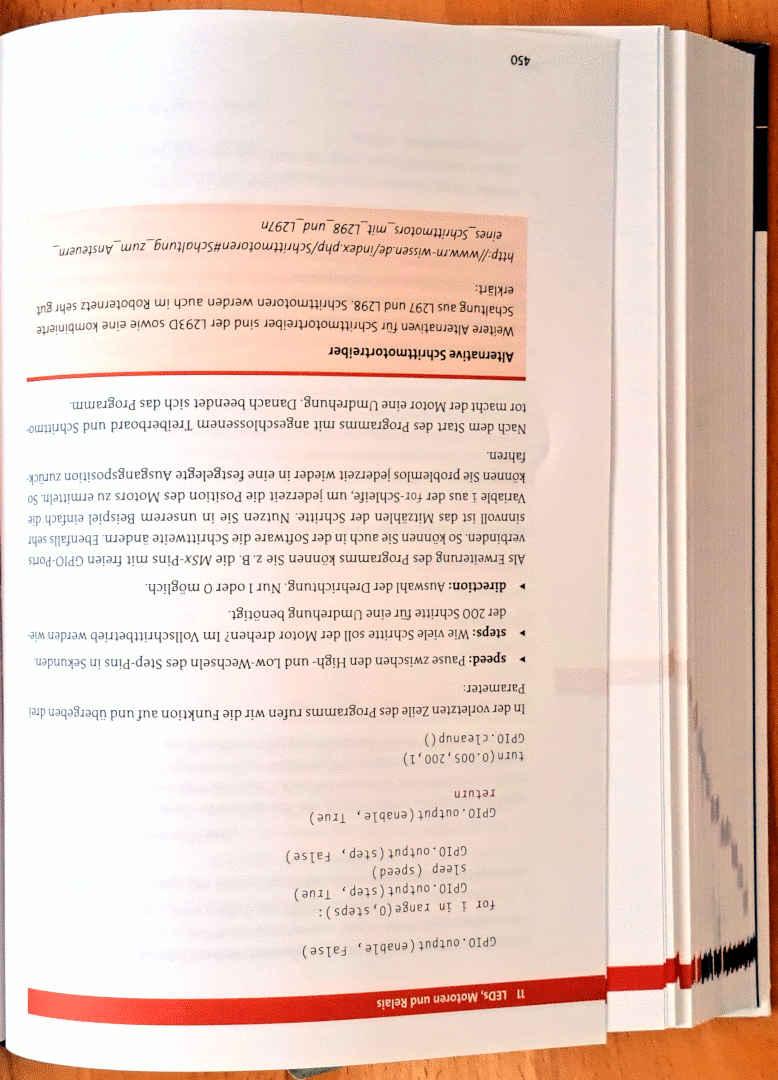
Alternativen für Schrittmotortreiber sind der L293D sowie eine kombinierte
Schaltung aus L297 und L298. Danach beendet sich das Programm.
Nach dem Start des Programms mit angeschlossenem Treiberboard und Schrittmo-
tor kann Sie jederzeit wieder in eine festgelegte Ausgangsposition zurück
fahren.
Variable
In V+ +In Out PD0 PC4 SenseB Q3 V- Sense PD1 PC3 SenseA Q4 T o _ S c h rittm o to r INA106 PD2 PC2 L298N PD3 PC1 PD4 PC0 VCC VCC GND GND AREF IC2 PB6 AVCC R/C VCC IC3 OSC REF.2 CLK Vcc PB7 PB5 SYNC REF.1 PD5 PB4 PWEN VSENSE2 Din IN1 OUT1 Vout PD6 PB3 IN2 OUT2 IN3 OUT3 LOAD REF PD7 PB2 IN4 OUT4 T o _ L
There is no system level requirement to maintain the accuracy for inputs less than 24. L6506 & L6203/L298 Microstepping drives can be implemented using the L6506 controller and bridge IC's like the L6201, L6202, L6203 and L298. The main difference between the standard half step application and a microstepping
12 INPUT3 OUT3 14 ENABLE 14 INPUT4 OUT4 9 9 9 9 SENS1 8 V V V V 4 13 GND D B D B D B D B 6 A SENS2 L298 7 B 11 9 D CNTL 5 INH1 SYNC 1 8 INH2 HOME 3 GNDGNDGNDGND 2 GND 2 , 1 , R 0 R 0 L297 GND GND GND GND Aufzugssteuerung 1)
OUT2 3 GND 10 INPUT3 OUT3 13 12 INPUT4 OUT4 14 14 9 9 9 9 8 GND 5 Y 6 Y7 Y 8 Y 13 D B D B D B D B L298 11 1 3 2 , 1 , GNDGNDGNDGND R 0 R 0 GND GND GND 1)
OUT3 13 P +C4 PB5(SCK) 19 12 INPUT4 OUT4 14 7 7 7 7 2u2/16V IC1 8 GND 2 2 2 2 5 Y 6 Y 7 Y 8 Y GND R2 L298 D B D B D B D B $ P GND 10k R-MOTOR o Motor Rechts 2 4 6 8 1 c M n o C 2 1 1 3 5 7 9 P P J I GND GND 16.12.09 09:03 f=0.90 /home/lucabert/eagle/Motorensteuerung/motorensteuerung.sch (Sheet: 1/1)
18 10 INPUT3 OUT3 13 $ +C4 PB5(SCK) 19 12 INPUT4 OUT4 14 P 2u2/16V IC1 8 2 2 2 2 GND V V V V GND L298 D B D B D B D B 1 R2 P GND r 10k R-MOTOR 0 c Motor Rechts 2 4 6 8 1 n M n C 2 1 1 3 5 7 9 P P J I GND GND 16.12.09 13:22 f=0.90 /home/lucabert/eagle/Motorensteuerung/motorensteuerung.sch (Sheet: 1/1
18 10 INPUT3 OUT3 13 $ +C4 PB5(SCK) 19 12 INPUT4 OUT4 14 P 2u2/16V IC1 8 2 2 2 2 GND V V V V GND L298 D B D B D B D B 1 R2 P GND 9 0 1 0 o 10k R 1 R 1 R-MOTOR 0 c Motor Rechts 2 4 6 8 1 n M n C 2 1 1 3 5 7 9 P P J I GND 16.12.09 14:01 f=0.90 /home/lucabert/eagle/Motorensteuerung/motorensteuerung.sch
18 10 INPUT3 OUT3 13 $ +C4 PB5(SCK) 19 12 INPUT4 OUT4 14 P 100n/16V IC1 8 2 2 2 2 GND V V V V GND L298 D B D B D B D B 1 R2 P GND 9 0 1 0 o 10k R 1 R 1 R-MOTOR 0 c Motor Rechts 2 4 6 8 1 n M n C 2 1 1 3 5 7 9 P P J I GND 16.12.09 22:41 f=0.90 /home/lucabert/eagle/Motorensteuerung/motorensteuerung.sch

 Bild
Bild
 Bild
Bild
 Bild
Bild
 Bild
Bild
 Bild
Bild
 Bild
Bild
 Bild
Bild
 Bild
Bild
 Bild
Bild
 Bild
Bild
 Bild
Bild
 Bild
Bild
 Bild
Bild
 Bild
Bild