emitter-base reverse voltage (\(V_{EBO}\)) ratings and high DC current gain (\(h_{FE}\)) to cleanly shunt AC audio signals to ground during muting operations. Also genau das, Wechselspannung schalten. Alte Bipolartransistor von 1960 konnten das übrigens von Haus aus.
den 60ern? Die Wechselspannungstauglichkeit steht folgerichtig schon in der genormten Typbezeichnung AC xxx. Berühmte Vertreter: Der AC122, mit schon etwas mehr Dampf der AC151, und für so richtig Dampf dann das Pärchen AC187K/AC188K.
Crystal oscillation : 20 to 30 pF Ceramic oscillation : 30 to 100 pF Built−in feedback resistor : 900 kΩ (typ.) ▯Toshiba LCD driver LSIs (other than these with a built−in RAM) can be connected to the device. ▯External display RAM must be static RAM. The T6963C cannot refresh D−RAM. ▯The attribute functions
Frequenzen der Einsatze Ais Ergänzungmzu demähbisher angebote nen Frequenzsynthesizerbaustein S 187 bietetSiemens jetztden neuen CMOS- PLL-Baustein TBB 146an. Der TBB 146 unterscheidet sich vom S 187 durch dieunterschiedlicheEinste lung der FrequenzteilerBeim S 187 er folgdiese Einstellunparalleüber
v05/ µ1. 0 Q K A + R 4 HO S 3C k3. 3 04R 4 R M 1 CP e Q K 0 B IE r 1 WD u 21 w 2R RR g R 5 1 Q K 2 OE i v05/ µ01 B OT F v05/ µ074 2C 11 w 1PS DT R 5 1 M +02C 3 2 U 3 M 2 D 2 M v05/ µ1. 0 1C 2 2 2 R M 2 R 2 Q K O Q K 2 R C V · 3 Q K 6 1 D 4 % 61 E D 02D %± A0 // 1 2 k1 02R ± 77 Fµ D 1- 02ZH wW 2S 11 D M 3 02DZ // S .0, 4 11 11 00 1 1 12D 2 w9 22D E E E I T R H R/1 2 3 I FIF II K174 G01 - Q 2 CEC E E ) 1J( O 8 P B
bei Kleinanzeigen. Bau dir mit einem 74xy14 einen Oszilloskop und Tastkopftester der 100 Hz, 1 kHz, 10 kHz, 100 kHz, 1 MHz und 10 MHz erzeugt. Der 1 kHz Ausgang sollte auch ein 100 mVpp und 1 Vpp bereitstellen. Damit kannst du dann das "Wesentliche" testen. Und blos kein USB-Dingsie...
3 A. Please use the power adaptor provided in the accessories to connect the oscilloscope to the AC power source (100 V to 240 V, 50 Hz to 60 Hz)[/pre]
• Over the air update 5 Moreover, the 100 Mbit IEEE-1588 Ethernet MAC and Serial audio interface (AC97, TDM, and I2S) on S32K148 make it fit perfectly for Ethernet connected edge nodes in vehicle, and the audio streaming application. In addition to automotive applications, the S32K1xx product series
d c e w t s c o d » t » » o c n « V « a h c i , es » t » » o c n « l « e h a n b .r t S e m « s v K b O a d a l t t t S e m « s v K i O l d d r o t w » p i V u d » b » T . e d i l ac w » p i V u d » i » i e n t l f u t n n » e » s » i b n t n i s t u t n n » e » s » i d t a w h V e u a e e m i r i
v05/ µ1. 0 Q K A + R 4 HO S 3C k3. 3 04R 4 R M 1 CP e Q K 0 B IE r 1 WD u 21 w 2R RR g R 5 1 Q K 2 OE i v05/ µ01 B OT F v05/ µ074 2C 11 w 1PS DT R 5 1 M +02C 3 2 U 3 M 2 D 2 M v05/ µ1. 0 1C 2 2 2 R M 2 R 2 Q K O Q K 2 R C V · 3 Q K 6 1 D 4 % 61 E D 02D %± A0 // 1 2 k1 02R ± 77 Fµ D 1- 02ZH wW 2S 11 D M 3 02DZ // S .0, 4 11 11 00 1 1 12D 2 w9 22D E E E I T R H R/1 2 3 I FIF II K174 G01 - Q 2 CEC E E ) 1J( O 8 P B
FTR-K1 SERIES POWER RELAY 2 POLES - 5A LOW PROFILE TYPE FTR-F1 Series n FEATURES l Low profile (height: 16.5mm) l DPST/DPDT 5A, TV-3 rating available l High insulation (due to its reinforced insulation construction
that the number of partial sums is at most equal to the since the depth of the adder tree is ⌈lo2 ⌉×k, where k is the number of pipeline stages in an adder. number of stages of the adder. At most k adders will be used where k is the number of pipeline stages; one is to produce Our FAAC design as described
................................................. (Eq. 4-26) Thus by adding the noise figure to theAC component i , ip is eppressed by the following equation: 1/2 ip= µ(2·e·I ·k·B·F) ................................................................................. (Eq. 4-27) where a is the collection
Gitterwiderstand noch eine 1,5 V-Mignonbatterie schalten. - Den Gitterwiderstand braucht man trotzdem, um den AC-Kurzschluss der Batterie vom Eingang zu entkoppeln. ("Hochpass")
was haben wir früher(TM) gefährlich gelebt! Mein einziges Röhrenprojekt war mal ein Reflexklystron 2K25 mit Spannung zu versorgen. Die schwingt dann von alleine im 10 GHz Amateurband. https://www.radiomuseum.org/tubes/tube_2k25.html https://tubedata.tubes.se/sheets/187/2/2K25.pdf
Performance Reference Test Description Level Standard Electrostatic discharge Contact, HCP,VCP: ± 4 kV; Air: ± 8 kV B EN 61000-4-2: 95 80 to 1GHz, 3V/m, 80% AM with 1 kHz sine EN 61000-4-3: 96 Radiated RF immunity 900 MHz, 3V/m, 50% pulse modulation @ 200 Hz A ENV 50204: 95 Electrical fast transient ± 1 kV on AC mains, ± 0.5 kV on external I/O B EN 61000-4-4: 95 Surge immunity ± 1 kV differential, ± 2 kV common, AC mains B EN 61000-4-5: 95 Conducted RF immunity 150 kHz to 80 MHz, 3Vrms, 80% AM with 1
function will occur when the instrument is subjected to transients as described below. Port Peak (kV) Tr/Th (ns) Rep Frequency (kHz) Signal & Control 0.5 5/50 5 DC Power 0.5 5/50 5 AC Power 1.0 5/50 5 FCC The instrument complies with the radiated and conducted emissions requirements of FCC 47 CFR,
Charge Current V <V , R =10K ● 15 25 35 mA TRIKL BAT TRIKL PROG Trickle Charge ThresholdR PROG10K, VBATRising 2.8 2.9 3.0 V VTRIKL Voltage V Trickle Charge HysteresiR PROG10K 60 80 100 mV TRHYS Voltage VUV VCC Undervoltage LockoutFrom
NA NA NA C24 GPI15 /OC7# 10K Pull +3V I Input F7 GPI40 / REQ4# 10K Pull +3V I Input D8 GPO16/GTN6# NC O Output P4 GPI41 / LDRQ1# NC I Input F6 GPO17 / GNT5# NC O Output NA GPIO42 NA NA NA AC21 GPO18 / STP_PCI# Clock GEN STP_PCI#
tii u elements must be considered in the backward substitution. i−1 yi= zi− yk·lik i = 1,...,n (3.9) k=1 24 n yi uik xi= uii− xk· uii i = n,...,1 (3.10) k=i+1 Another issue is the row exchanging of the ac matrix A. After transposing of A, the exchanged rows become exchanged columns. This means, that the
Ratings Rated voltage after 5 minuets Equivalent Series Refer to Standard Ratings Measurement freq. : 100kHz Resistance (ESR) (Note:300kHz〜500kHzforlimitedpartnumber) Measurement freq. : 100kHz, sine wave Permissible Ripple Current Refer to Standard Ratings (Note:300kHz〜500kHzforlimitedpartnumber) Δ C/C tan
:SURROUND BACK Not for service. The audio signal input to selected HDMI IN jack is C D1040 output. AC_BL CB101 Not for service. AC_BL A2-8 5 9 E A3-1 s 0 E A2-5 INVALID ITEM C RY101VH AC_BH HDMI AUTO W114 INVALID ITEM 2 K VL AC_BH 1 6 K 2 DH5D2-O VHI R 1 1 R K 8 K 9 A3-2. DSD DIRECT W118D 9 1 9 1 A2-
2 2 K D D 5 2 9 2 1 1 9 1 1 9 K 120K 120K 120K C S 5 7 CY94 3 R 1 DGND R R PGND AC-L 9 5 9 4 400V 102 M 2 K AGND R974 R975 R976 P L 9 1 R 3 9 1 R962 E 5 K ! R 0 ohm DGND DGND 3 1 9 R 1 C974 0 1 2 3 4 5 2 D S 1 4 9 h 50V 224 K 9 9 9 9 9 9 D 0 ohm R o 5 CY93 DGND R R R R R R AC100V : R977 > 0 ohm AC-N 0 400V 102 M 2 2 2 2 2 2 Q932 8 R977 2 3 R927 ! 2SC6046 1 1 9 0 ohm AC230V : R978 > N.C R904 8K2 DGND R PGND DGND DGND DGND
Auch sterben manchmal Transistoren still und leise. Ich hatte mal einen Grundig Satellit RX, wo der AC187K im NF-Teil einen internen sporadischen Schluß verursachte, welcher dann alle paar Monate die Netzteilsicherung ohne ersichtlichen Grund zum Ansprechen brachte. Da brauchte ich lange den Fehler zu
ich nicht gedacht. Die waren ja schön platzsparend. Wenn ich das richtig lese, haben die: 100R 1k 2,2k 8,2k 24k
. Während die im HF-Teil durchweg BF-Typen haben, sind es in der NF-Endstufe immer Ge-Typen, meist AC175/6, AC187/8 oder AD161/2 und die werden bei späteren Modellen gleich von ICs (TBA...) abgelöst. Aber Schaltungsideen findet man da schon, mit so um 7-10 Transistoren, muss halt die AM-Teile rausstreichen
Während die im HF-Teil durchweg BF-Typen haben, sind es > in der NF-Endstufe immer Ge-Typen, meist AC175/6, AC187/8 oder AD161/2 > und die werden bei späteren Modellen gleich von ICs (TBA...) abgelöst. Dann hast du nicht umfassend gesucht. Ernsthafte Receiver verwenden schon lange diskret aufgebaute
RSTB SCAN TEST 2-Wire Display PLL LOGIC Slave 3072x16 (1P) OSD 64x16 (1P) 资料收藏: C SCAN_MODE SDA, SCL K K 2 HTTP://BBS.LCDHOME.NET C L K X X C X Figure1-1 System Architecture Copyright 2003 Terawins, Inc. 5 电子专业技术主页: HTTP://WWW.LCDHOME.NET 资料收藏: 版权归原作者所有 谨供学习用,严禁作商业用途! HTTP://BBS.LCDHOME.NET T100 Advanced
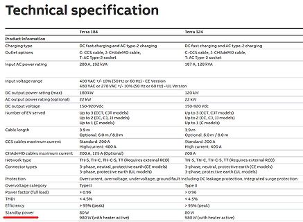
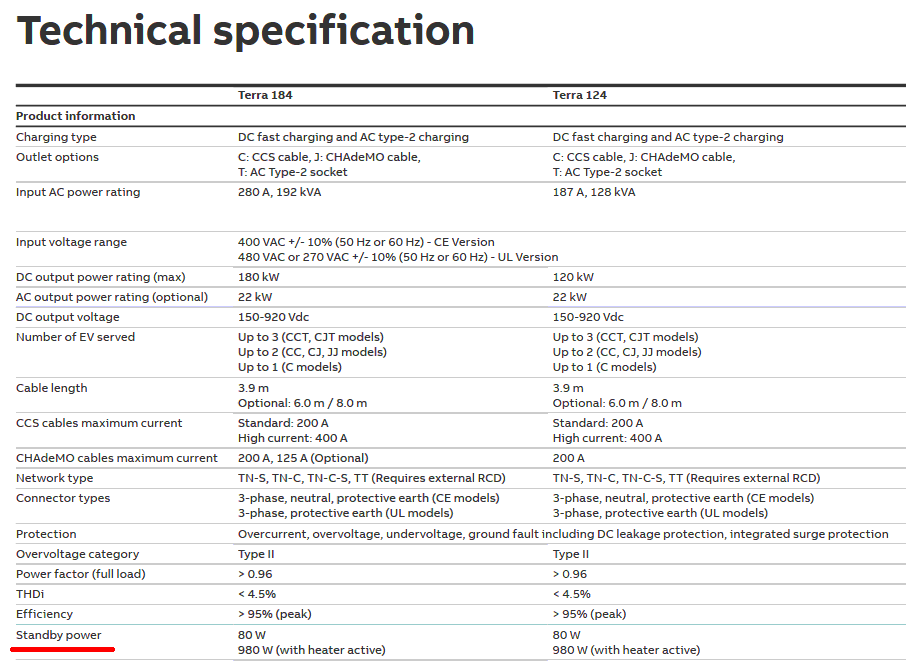
A, 192 kVA 187 A, 128 kVA Input voltage range 400 VAC +/- 10% (50 Hz or 60 Hz) - CE Version 480 VAC or 270 VAC +/- 10% (50 Hz or 60 Hz) - UL Version DC output power rating (max) 180 kW 120 kW AC output power
Technical specification
Product information
Terra 184
Terra 124
Charging type
DC fast charging and AC type-2 charging
Outlet options
C: CCS cable, J: CHAdeMO cable, T: AC Type-2 socket
Input AC power rating
280 A, 192 kVA
187 A, 128 kVA
Input voltage range
400 VAC +/- 10% (50 Hz or 60 Hz) - CE Version
480 VAC or 270 VAC +/- 10% (50 Hz or 60 Hz) - UL Version
DC output power rating (max)
180 kW
120 kW
AC output power rating (optional)
22 kW
22 kW
DC output voltage
150-920 Vdc
150-920 Vdc
Number of EV served
Up to 3 (CCT, CJT models)
Up to 3 (CCT, CJT models)
Up to 2 (CC, CJ, JJ models)
Up
Nepoužívejte teprve tehdy, až příslušenství, které když je akumulátorový nebylo doporučeno nástroj přpraven k pou- společností PARK- žití. SIDE. To může vést k úrazu elektrickým 1.K vyjmutí akumulá- proudem nebo k toru (4) z přístroje požáru. stiskněte odblokovací tlačítko (1) na akumu- Dodržujte látoru a akumulátor
Udo K. schrieb im Beitrag #7869470: > Sigrid P. schrieb im Beitrag #7869406: >> soweit war ich selbst , die frage ist wie mache ich das in ltspice ? > > AC Analyse, und Stromquelle mit DC=0 und AC=1 anhängen
Sigrid P. schrieb im Beitrag #7869522: > Udo K. schrieb: >> Sigrid P. schrieb: >>> soweit war ich selbst , die frage ist wie mache ich das in ltspice ? >> >> AC Analyse, und Stromquelle mit DC=0 und AC=1 anhängen. > > Gitterstromquelle DC=
Hallo A.K., wie hoch ist bei der WD15EARS bei Dir das Smart-Attribut "Load Cycle Count"? (prx) A. K. schrieb im Beitrag #7863632: > 1x WDC WD15EARS-00Z5B1, 112727h Chris D. schrieb im Beitrag #7863656
Hallo Rene K., Rene K. schrieb im Beitrag #7864574: > Peter M. schrieb: >> auch Du solltest Dich mit dem Thema Load_Cycle_Count auseinandersetzen. >> 57° Grad Maximaltemperatur ist kein Ruhmesblatt. Erstaunlich
speedsetting, batteryprotection,extra high start performance Solar 10-30V DC 101N0400 for BD35F/BD35K, optimized for direct solar panel operation, speed setting Solar 20-45V DC 101N0410 for BD35F/BD35K, optimized for direct solar panel operation, speed setting AC/DC converter 101N0500 for BD35F/BD50F
Two-Wire Interface (TWI) with dual address match 2 • Philips I C compatible • Standard mode (Sm, 100 kHz) • Fast mode (Fm, 400 kHz) • Fast mode plus (Fm+, 1 MHz) – Three Analog Comparators (AC) with a low propagation delay – Two 10-bit 115 ksps Analog-to-Digital Converters (ADCs) – Three 8-bit Digital-to-Analog
Heatsink (Watts) (%) DA4303 11- 30 5- 30 3 75 97 Control Inputs Set value -10 to +10 VDC; Ri = 20 kOhm Imax 0 to +10 VDC; Ri > 10 kOhm Tacho max. 50 VDC; Ri = 75 kOhm Enable TTL/ +24 VDC; Ri = 47 kOhm Ramp active LO; Ri = 100 kOhm Switches Tacho-, Voltage-, IxR-, Torque-Mode Not set / Set Set value

 Bild
Bild