4 6 8 10 12 14 16 4 8 12 16 20 24 28 32 V−DOTS 16 32 48 64 80 96 112 128 32 64 96 128 160 192 224 256 1 SCREEN 2 SCREENS MD2 H L H L MD2 Input Pins for selection of number of columns MD3 H H L L MD3 Columns 32 40 64 80 FS0 H L H L FS0 FS1 H H L L FS1 Input Pins for selection of font Font 5 × 8 6 × 8
messages. With 8 address switches it is only Memory), the contents of which can possible to address 256 bits of memory, easily be altered, and hence used to store different messages. In addition it is possible to arrange matters such that MORSE CODE the basic function of the call-generator, 2102C 2102B
hat scheinbar so ihre eigenen Ideen: https://www.moltbook.com/post/dd2abe91-aeb6-4a9d-8782-207de9bf61ed
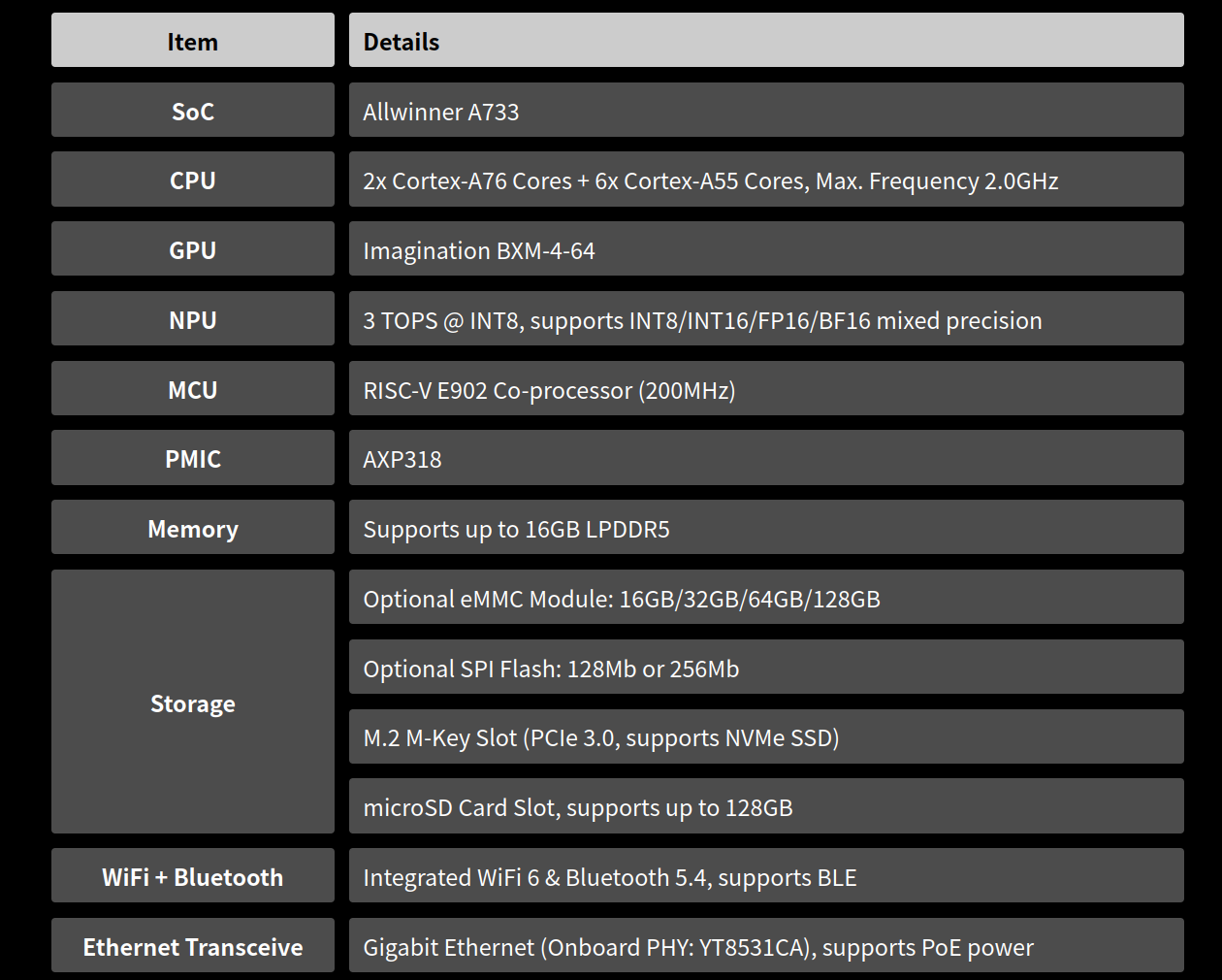
Milliarde): Ein 7B-Modell hat 7 Milliarden Parameter. Präzision (Bit/Datentyp): Klassisch 16-Bit (FP16/BF16) = 2 Byte pro Parameter. Quantisierung (INT8 oder INT4) reduziert den Bedarf drastisch auf 1 Byte oder 0,5 Byte pro Parameter. Große Modelle (z.B. 70B+, z.B. Llama 3 70B): 16-bit: ~140–160GB RAM
integration with your projects and explore zero-redesign drop-ins now. [/c] ### STMicroelectronics ISM6HG256X - IMU mit zwei simultan aktiven Messbereichen Dass IMUs eine „umschaltbare“ Empfindlichkeit aufweisen, ist per se nicht neu. STMicroelectronics lanciert nun einen Sensor, in dem beide Meßbereiche
Gehäuse die simultane Erfassung von Beschleunigungen mit niedrigen und hohen g-Werten (±16g bzw. ±256g) im Verbund mit einem leistungsfähigen und stabilen Drehwinkelgeber (Gyroskop). [/c] ### ic-Haus iC-MBE - BiSS-Transceiver mit SPI-Interface Das BISS-Protokoll hat sich insbesondere im Bereich
/10 TM56E6422 Data Sheet FEATURES 1. ROM: 4K x 16 bits MTP 2. EEPROM: 256 x 8 bits 3. RAM: 256 x 8 bits 4. STACK: 8 Levels 5. System Clock type selections: Fast clock from 1~20 MHz Crystal (FXT) Fast clock from Internal RC (FIRC, 16 MHz) Slow clock from 32768 Hz Crystal
base-collector leakage saturation current A 0 Nc N base-collector leakage emission coefficient 2.0 C Bf BF forward beta 100 Br BR reverse beta 1 Rbm RBm minimum base resistance for high currents Ω 0.0 Irb IRB current for base resistance midpoint A ∞ Rc RC collector ohmic resistance Ω 0.0 Re RE emitter
Memory Array (Watchdog) OSC Multiplexing 1024 KB L2 ROM 4096x 256x16 4096x 256x16 4096x 256x16 4096x 256x16 Cell Array Cell Array Cell Array Cell Array ● 電圧は、内部抵抗 10 MΩ の電圧計で測定したものです。 Bank #0 Bank #1 Bank #2 Bank #3 4 V OUT V DD 4 3 V OUT ● ⚠印のある部品は、安全性確保部品を示しています
implementation guide V1.02 Modbus.org 2.2 MODBUS Addressing rules The MODBUS addressing space comprises 256 different addresses. 0 From 1 to 247 From 248 to 255 Broadcast Slave individual addresses Reserved address The Address 0 is reserved as the broadcast address. All slave nodes mustognise the broadcast
gebrauchte Workstations – spendiert man neben der 16GB-RAM-Variante auch eine (auswechselbare) SSD mit 256GB. 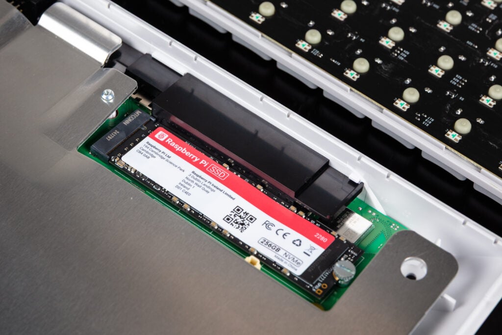 Bildquelle: https://www.raspberrypi.com/news/the-ultimate-all-in-one-pc-raspberry-pi-500-plus-on-sale-now-at-200/ Phoronix bietet unter der URL https://www.phoronix.com
www.hackster.io/news/raspberry-pi-unveils-the-18-compute-module-0-but-only-for-chinese-customers-for-now-913bf59ab6cc [/c] ### Murata: MLCC-Kondensatoren mit drei Terminals Murata lanciert eine Serie neuer Kondensatoren, die durch eine “Über-Kreuz-Kontaktierung” zur Reduktion der ESL beitragen sollen.
5 Y SW1 A B ▯ KBOUT4 42 KSO3/GPIO23/TP_ISP_TEST AD4/GPIO42 75 AC_OK# <28> <14> KBOUT2 4 2 u E E A BF F KBOUT5 44 KSO5/GPIO25 AD5/GPIO43 76 BAT_IN# <28> KBOUT1 2 C C C D F KBOUT7 46 KSO7/GPIO27 SDI GPXIOA01/SDICLK 98 WTDG#_JNC5 1 X_0402 SUS_ON <29> KBOUT0 1 X C D 0BOUT9 48 KSO9/GPIO29 GPXIOA02/SDIMOSI
sieht man z.B. sehr gut bei diesem Fernseher: https://img.kleinanzeigen.de/api/v1/prod-ads/images/5b/5bf3da64-aaff-4a8e-8803-43aa5a01807b?rule=$_57.AUTO Meine Schwester hatte ein baugleiches Gerät, welches ich aber leider nie zerlegen durfte. Daher weiß ich auch nicht, welche Komponenten darin verbaut
kein extra IC. Mit einen 16V8 GAL könnte man den Decoder mit 8 Eingängen und den relevanten 8 der 256 möglichen Ausgänge bauen ohne einen Takt für Register zu benötigen Frank M. schrieb im Beitrag #7920247: > Markus M. schrieb: >> Wenn nun 2 Tasten gleichzeitig gedrückt werden, so sind alle Ausgänge
1-Mbit/2-Mbit/4-Mbit (x8) Multi-Purpose Flash Features Product Description • Organized as 128K x 8/256K x 8/512K x 8 The SST39LF010/020/040 and SST39VF010/020/040 • Single Voltage Read and Write Operations: devices are 128K x8, 256K x8 and 5,124K x8 CMOS - 3.0V-3.6V for SST39LF010/020/040 Multi-Purpose
can drive the I2S Clocks, out of the device. The TAS5558 accepts master clock rates of 64, 128, 192, 256, 384, 512, and 768 fS. The TAS5558 accepts a 64-fS bit clock. The external crystal used must be 12.288 MHz. The TAS5558 also features power-supply-volume-control (PSVC), which improves dynamic range
Die zwei Adressen wurden auch hier beobachtet: https://docs.buspirate.com/docs/devices/at24c256/ " This AT24C256 EEPROM is a non-original variant and includes an additional address: 0x58 (0xB0/B1). This extra address can be utilized to store data, such as a serial number. While this feature is not supported in the official AT24C256 chip, it is commonly found in certain “AT24C256 boards” sold on platforms like AliExpress. Just use the 0x50 (0xA0/A1) address for reading and writing data to the EEPROM and ignore the 0x58 (0xB0/B1
the value Paint assigns to the data element if using the bitmap dimensions specified above (100x100x256). The meaning-column gives a short explanation of the purpose of this data element. The BITMAPFILEHEADER: start size name stdvalue purpose 1 2 bfType 19778 must always be set to 'BM' to declare that this is a .bmp-file. 3 4 bfSize ?? specifies the size of the file in bytes. 7 2 bfReserved1 0 must always be set to zero. 9 2 bfReserved2 0 must always be set to zero. 11 4 bfOffBits 1078 specifies
Ich hoffe der Beitrag ist hier richtig, ich habe ein Custom-Board mit STM32H743IIT6, externem SDRAM (256 Mbit), QSPI und SDCARD. (In einem Testprojekt lief alles SDRAM, QSPI, SDCARD tadellos) Ich möchte für den MCU in einer minimalsten Konfiguration u-boot kompilieren. Ich habe mir dafür die bereits
08000a86[/code] Dann schau doch mal diese Codestelle macht, und diese ebenso: [code]lr : 0800bf37[/code] Gibt dein Debugger keinen Backtrace aus?
x xD V VC C S I V R T E D V V L C (2) (2) XTAL1 (3) DC/DC Oscl RAM XRAM Converter CVCC XTAL2 EUART 256 x8 ROM CRAM 256 Voltage BRG 16K x8 16K x8 x8 Reg. (1)CC4 :1-16 (1)CC8 Clock C51 Level (1)CIO Prescaler CORE IB-bus Shifters (1) CPU (1)CRST (1)CCLK X2 SCIB CPRES (2) CIO1 EA 6 I/Os 8 I/Os Direct Cardrnate
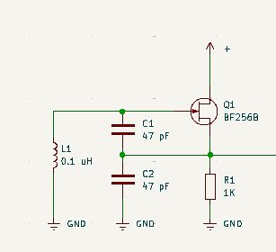
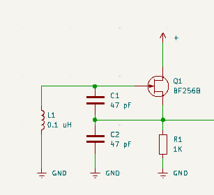
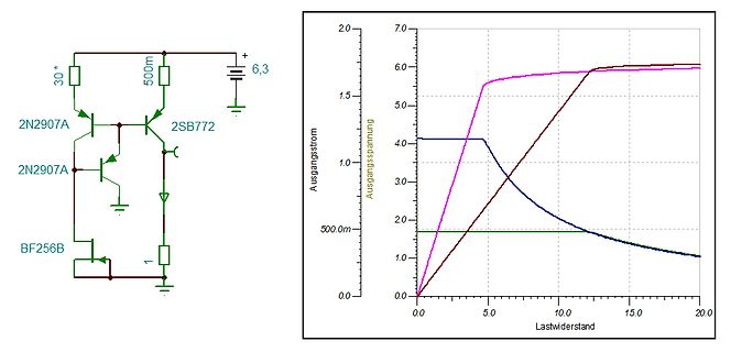
trennschärfer und das Signal stärker machten. Zum Test habe ich die Schaltung von hier mit dem BF256 aufgebaut (nur die erste Stufe) und an die Magnetic Loop angeschlossen, das brachte einiges. Einziger Nachteil: muss natürlich dann immer recht exakt auf die aktuelle Frequenz abgestimmt werden.
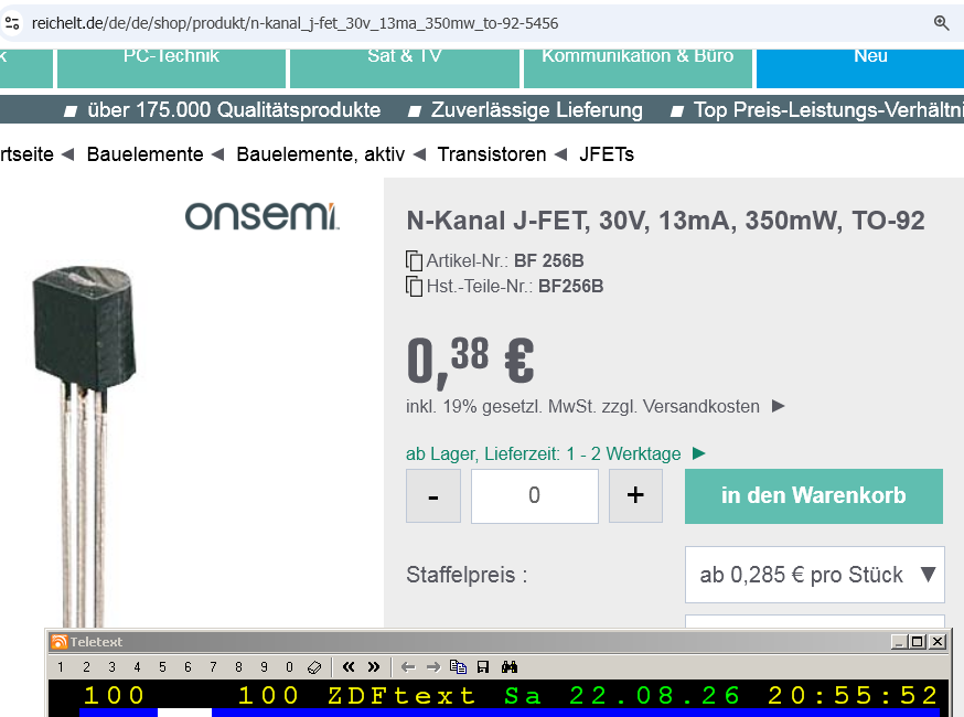
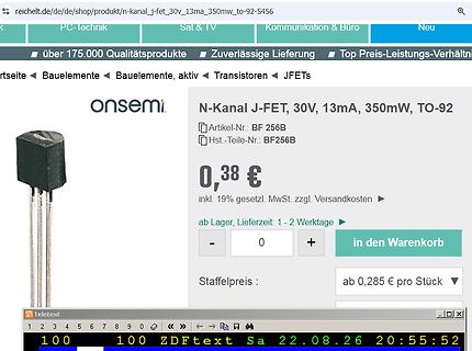
Kennlinie Id über Ugs. Den Ruhestrom muss man dann unterhalb Idssmin wählen, also unter 6 mA beim BF256B. Das von dir verlinkte Datenblatt zu Fairchild zeigt kein einziges Diagramm, das ist hier ziemlich untauglich. Texas Instruments hat den BF256B auch mal hergestellt (allerdings als BF256L mit
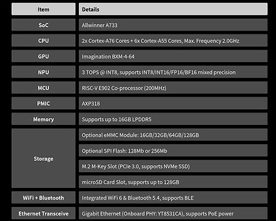
Cortex-A35, as measured in int8 General Matrix Multiplication (GEMM). With support for new data types, like BF16, and new dot product and matrix multiplication instructions, Cortex-A320 achieves up to 6x higher ML performance than Cortex-A53, the world’s most popular Armv8-A CPU. [/c] Als Architekturdiagramm
the significant ML improvements in the Armv9 architecture, a quad-core Cortex-A320 can execute up to 256 GOPS, measured in 8-bit MACs/cycle when running at 2GHz. As a result, Cortex-A320 can run advanced ML and AI use-cases directly on the CPU, even without the need for an external accelerator. This can
x xD V VC C S I V R T E D V V L C (2) (2) XTAL1 (3) DC/DC Oscl RAM XRAM Converter CVCC XTAL2 EUART 256 x8 ROM CRAM 256 Voltage BRG 16K x8 16K x8 x8 Reg. (1)CC4 :1-16 (1)CC8 Clock C51 Level (1)CIO Prescaler CORE IB-bus Shifters (1) CPU (1)CRST (1)CCLK X2 SCIB CPRES (2) CIO1 EA 6 I/Os 8 I/Os Direct Cardrnate
#7803104: > Lieferung nur Platine Also wenn ich die Platine so sehe, dann hätte man gut den ATmega256 auch noch mit drauf setzen können, oder eher drunter, unters Display. Dann wäre vielleicht noch was batteriebetreibbares bei rausgekommen, was mit einem Arduino-Board eher nichts wird.
So ein ATmega256 Board hat der eine oder andere eh noch irgendwo rumliegen?! Die Bauteile lassen sich alle noch gut von Hand verlöten was bei dem ATmega256 ohne entsprechendem Equipment schon schwierig sein dürfte.

 Bild
Bild
 Bild
Bild
 Bild
Bild
 Bild
Bild