Europlatine inkl. Lack, E-Test, Best.-Druck doppelseitig für 117,81€ inkl. MwSt in 10 Tagen + Versand max. 4 lagig Bestückungsdruck doppelseitig Bohrungen no limit min Clearance 0,15mm (Standard) min Bohrdurchmesser 0,3mm (Standard) Gerber/Eagle/Protel/Target mehrere Leiterplatten können auf einer Europakarte
? ? PCB Pool 99,41 137,58 319,91 x Q-print/Q-PCB 96,80 166,90 834,48 x Onlineshop WEdirekt 145,18 190,64 379,49 x Kleinmengen. Sollen nur wenige und/oder sehr kleine Platinen gefertigt werden, verschieben sich sehr oft die Relationen. Viele Fertiger haben auch beim Pooling eine Mindestgröße, unter der
Japan Capacity 1) Minimum 1900mAh 14.35 mm Nominal Voltage 1.2V Charging Current x Time Fast Charge 2) Max.1900mA Charge Fast Charge 2) 0°C - 40°C Condition Discharge Condition -20°C - 50°C 50.4 mm Ambient Temp. Less than Storage 90days -20°C - 40°C Condition Less than -20°C - 30°C 1year Internal Impedance
EPM5016 NONE No Need WMAX V5.03 ALTERA PLD EPM5032 NONE No Need WMAX V5.03 ALTERA PLD EPM5064 ADP-MAX50B No Need WAMAX V5.05 ALTERA PLD EPM5064(NEW ID) ADP-EPM5064-PL44 No Need WAMAX V5.05 ALTERA PLD EPM5128 ADP-MAX50C/-PG No Need WAMAX V5.05 ALTERA PLD EPM5128A/EPM5128(NEW ID) ADP-EPM5128A-PL/PG No
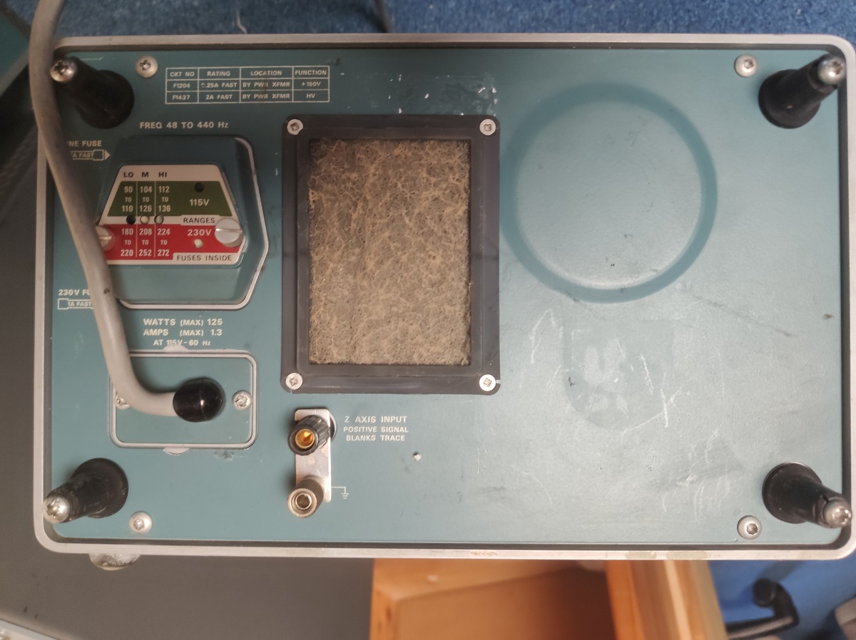
2A FAST PW8 XFMR HV
FREQ 48 TO 440 Hz
LO MI HI
90 104 112
110 128 136
115V
230V
RANGES
180 208 224
190 252 272
FUSES INSIDE
230V FU
FAST
WATTS (MAX) 125
AMPS (MAX) 1.3
AT 115V-60 Hz
Z AXIS INPUT
POSITIVE SIGNAL
BLANKS TRACE
hat der Installateur empfohlen: Vordruck 1,8 bar Soledruck 3,0 bar (habe 2,5 bar eingestellt) Den max. Höhenunterschied schätze ich bei meiner Anlage auf ca. 8 m Die Druckschwankungen (kalt/warm/Stagnation) beobachte ich um ein Versagen des Ausgleichbehälters zu erkennen. (ist älter als 15J und
Installateur empfohlen: > Vordruck 1,8 bar > Soledruck 3,0 bar (habe 2,5 bar eingestellt) > Den max. Höhenunterschied schätze ich bei meiner Anlage auf ca. 8 m Das scheint ähnlich meiner Anlage zu sein. Ich hatte da auch was von 2,5 Bar im Kopf. Wolf17 schrieb im Beitrag #8093761: > Hat die
Watt sind jetzt die Leerlauflast was ursprünglich mal vllt. 10-20 Watt waren. Es sind also noch 180-190 Watt an Arbeitsleistung da die sozusagen abgerufen werden könnten. Bei 150 Watt Leerlauf + Last von 180-190 Watt wären das 330-340 Watt Verbrauch. Aber ich denke nicht, dass der defekte Motor es schafft
nur um eine relative kurze Belastung. Ich meine, > irgendwo auf dem Gerät was gesehen zu haben wie max. 5 Minuten > einschalten und dann 15 oder 20 Minuten Pause/Abkühlen. Also ist das Gerät und der Motor nur für Kurzzeitbelastung mit einer ED von max. 20-25%. Da ist es normal, dass er im Betrieb
1/MAX9_2/MAX9_3) 9 devices draw less than 4µA supply current over Ultra-Low Quiescent Current (4µA, max) 7 temperature (MAX971/MAX972/MAX981/MAX982), and Over Extended Temp Range (MAX971/MAX981) 1 include
Source Current pin. Each comparator’s input operates from the negative n Pin Compatible with LTC1440, MAX921, MAX931 supplytowithin1.3Vofthepositivesupply.Thecompara - toroutputstagecancontinuouslysourceupto40mA.By APPLICATIONS eliminating the cross-conducting current that normally occur when the comparator
DEFINES A ZONE WHERE ALL T BODY AND LEAD IRREGULARITIES ARE S ALLOWED. INCHES MILLIMETERS 4 DIM MIN MAX MIN MAX Q A A 0.570 0.620 14.48 15.75 B 0.380 0.405 9.66 10.28 1 2 3 C 0.160 0.190 4.07 4.82 U D 0.025 0.035 0.64 0.88 H F 0.142 0.147 3.61 3.73 G 0.095 0.105 2.42 2.66 K H 0.110 0.155 2.80 3.93 Z J
Diese ist versorgt über einen Hager ADM466QC C16. In der Aussenküche nutze ich zwei Steckdosen als max 3,5KW (an einer hing der Ofen) und eine an der Kühlschrank und kleinverbraucher hängen. Da der Hager ja seinerseits 16A pro Phase hat sollte ja dann keine Sicherung/FI fliegen, oder? Was sie aber trotzdem
aktiv (glüht auch). - ebenfalls 60 Minuten ohne Probleme gelaufen, allerdings braucht er bis auf 190 Grad 45 Minuten. 160 Grad hatte er nach 25 Minuten. Ich denke, dass, wenn beide Phasen angeschlossen sind der Ofen die Leistung moduliert. Es gibt ja einen Leistungsbereich von 1300 bis 1600 Watt bei
tuning core as they does not implement core tuning. cod. SBK-50 useful space for the coil = 5,2 mm , max 10 turns , max wire Ø 0,3 mm, max inductance ~ 500 nH useful space for the coil = 5,7 mm , max 4,5 turns , cod. SBK-51 max wire Ø 0,6 mm, max inductance ~ 100 nH useful space price 0,45 € -- 0,40 €
character generator ROM (code 0101) T6963C−0101 is built in as standard. ▯External display memory : 64 KB Max The addresses in display memory of the text area, graphic area and external character generator area are determined by software. ▯Read or Write operations from the CPU do not disturb the display. ▯A
Save-Schaltfläche. Die automatische Helligkeitssteuerung verwendet dann bei einer Helligkeitsmessung diese Min-/Max-Werte zum Vergleich. Somit kann der Helligkeitsbereich bei der automatischen Helligkeitssteuerung komplett ausgenutzt werden. Hinweis: Es ist nicht sinnvoll, bei der Max-Messung einfach eine Taschenlampe
bestimmten Anzeigemodi. Bugfix SK6812: Rot und Grün vertauscht. Bugfix LDR: Nach dem Setzen eines neuen LDR-Max-Wertes wurde dieser nicht zurück an das Web-Interface übertragen und deshalb dort (bis zum nächsten Reboot) ein alter Max-Wert angezeigt. STM32 Version 2.1.0. Auslagerung des HTML-Codegenerators auf
a maximum height of 6 mm and, with the 6-segment collect&place head (S-27 HM), on components to a max. of 8.5 mm. The transport height can be set to allow the machines to be integrated into lines with 830, 900, 930 or 950 mm transport height. Communication between the PCB conveyors of the individual
CHARACTERISTICS: BUS MASTER MODEFLASH READ CYCLE Parameter Symbol Parameter Description Test Conditions Min Max Unit tMFR1 REF, SBHE,SA0–19 Setup 10 ns to MEMR tMFR2 REF, SBHE,SA0–19 Hold From 5 ns MEMR tMFR3 IOCHRDY to MEMR 0 35 ns tMFR4 MEMR Inactive 55 ns tMFR5 MEMR to BPCS 125 260 ns tMFR6 BPCS Active 190
A Max. Duty Cycle D MAX V FBV 100 % VFB0V, Vin=12V, moh Output Power PMOS Rdson SW=5A 60 80 m Rev 1.5 www.xlsemi.com 5 Datasheet 5A 180KHz 36V Buck DC to DC Converter XL4015 Typical SystemApplication (VOUT
Number code V ZI ZT f=1kH @I ZT IZT R V R @T =60°C Z amb tp=10ms V V Ω Αvz(10 /K) m A µ A V m A A Min. Max. typ BZY97C3V9 Y3V9 3.7 4.1 7.0 -0.025 100 15 1.0 366 3.7 BZY97C4V3 Y4V3 4.0 4.6 7.0 -0.020 100 10 1.0 327 3.4 BZY97C4V7 Y4V7 4.4 5.0 7.0 -0.020 100 5.0 1.0 300 3.1 BZY97C5V1 Y5V1 4.8 5.4 5.0 -0.010
Schaltbild aus dem Datenblatt vom LT3757 (s. Anhang). Was ist mit dem MOSFET? Ist ein 650V Typ z.B. IPP65R190C7 geeignet? Ich habe z.B. nicht gefunden, was die max. zulässige V_DG bei dem Bauteil ist. Ansonsten sollte der LT3757 die 325V ja gar nicht sehen, oder liege ich da falsch?
Ich habe mit dem LT3757A als Flyback ein Spannungswandler von 12V auf max. 200V für Nixieröhren gebaut. Geht wunderbar bei 10W Ausgangsleistung und einem Wirkungsgrad von ca. 90%. Gibt da ein gutes Beispiel im Datenblatt. Ob man 325V und 100W erreichen kann liegt dann eher
proof to battery and ground • Thermally protected. QUICK REFERENCE DATA SYMBOL PARAMETER MIN. TYP. MAX. UNIT VBAT supply voltage on pin BAT 5 12 27 V BAT supply current on pin BAT in sleep mode 1 3 8 A supply current on pin BAT in standby mode; bus recessive 100 400 1000 A supply current on pin BAT in
angle • 4.3~15.3 mm actuator • through hole SPECIFICATIONS parameter conditions/description min typ max units rated voltage 1 12 Vdc rated current 0.01 50 mA withstanding voltage for 1 minute 250 Vac contact resistance applying load of 2 times operating force at 5 Vdc, 10 mA 100 mΩ insulation resistance
example of a local time recorded on July 9, 2009 in Switzerland. local 2009-07-09 15:08:21 Thursday day 190 timezone UTC+2 UTC 2009-07-09 13:08:21 Thursday day 190 MJD 55021.54746 GPS 2009-07-09 13:08:36 week 1539 392916 s cycle 1 week 0515 day 4 Loran 2009-07-09 13:08:45 GRI 9940 472 s until next TOC 13:
Than MAX_FL Bytes and Bad CRC Statistic Register (ENET_RMON_R_JAB)....... 2053 57.5.71 Reserved Statistic Register (ENET_RMON_R_RESVD_0).......................................................................
Specifications: in the region of 2 kHz. s e n s i t i v i t y : 1 V peak The input signal is fed via the input max. input v o l t a g e :± 5 V peak stage T1 to the clock input of the input i m p e d a n c e :min. 4k7 max. measurement range : 1 MHz counter; diode D6 protects this input against large negative voltages
PART NUMBER RESISTANCE AT 25 °C (R25) TOLERANCE ON R25 VALUE MAX. STEADY-STATE CURRENT UP TO 65 °C MAX. RECOMMENDED ENERGY RATING MAX. VOLTAGE MAX. CAPACITANCE AT 120 V AC RESISTANCE AT 100 % MAX. CURRENT RESISTANCE AT 50 % MAX. CURRENT BODY TEMP. AT 100 % MAX. CURRENT
20 % R Rated RMS ripple current at 100 kHz, 105 °C Nominal case size: Ø 10 mm x 12 mm; Form TFA IL2 Max. leakage current after 2 minRat U tan δ Max. dissipation factor at 100 Hz Ordering code: MAL215035471E3 Former 12NC: 2222 150 35471 Z Max. impedance at 100 kHz Note • Unless otherwise specified, all
Egal was du machst, stelle sicher, daß die max. Wassertemperatur an deinem Heizstab überwacht wird und bei spätestens 90°C die Heizung abschaltet. Falls du kalkhaltiges Wasser hast, sollte die max. Temperatur 60°C betragen.
vermutlich an deinem mangelnden Vorstellungsvermögen. ja, offensichtlich Das heisst Euch stehen max 3 kW an Leistung zur Verfügung, egal ob für Heizung oder Warmwasser?
1.3 0.3 1.3 % Total Error Drift E (Note 6) -1.7 ±0.4 1.7 %FS TOT(D) Note 4: Typ values are 1. Min/max values are guaranteed by production test Note 5: Guaranteed by design and characterization. Typ values are 1, min/max values are 3. Note 6: Worst case numbers are based on 3 lots qualification data
routine examines the Rdown and Rup bits in the range control status register. Ifthe range > range max. then the instrument must range up. Ifthe range < range min. then the instrument must range down. Italso ensures that in the TRIGGER LEVEL function only manual ranging isallowed. 1.4.1.4. M e a s u
measure anode luminous sensitivity) VOLTAGE 0 V ON LIGHT LEVEL OFF 5 6 7 8 9 (minutes) 1 µA ANODE I max. OUTPUT Ii I min. OR Ii I max. I min. 5 6 7 8 9 (minutes) WARM-UP PERIOD (5 minutes or more) THBV4_0440EA Figure 4-40: Light hysteresis In light hysteresis test, the photomultiplier tube is operated
Codes Remarks reset Call macros Run normal macro N n1 Call the (normal) macro with the number n1 (max. 7 levels) Run touch macro T n1 Call the touch macro with the number n1 (max. 7 levels) Run menu macro ESC M M n1 Call the menu macro with the number n1 (max. 7 levels) Run port macro P n1 Call the port macro with the number n1 (max. 7 levels) Run bit macro B n1 Call the bit macro with the number n1 (max. 7 levels) automatic (normal-) macros Call the (normal) macro with the number n1 in n2/10s. Execution is stopped by commands
25°C(Note2). V =V =EN =EN =10V, MODE=0V, R =200kΩ A IN_P IN_N T SYMBOL PARAMETER CONDITIONS MIN TYP MAX UNITS Boost Charge Pump VIN_P VIN_PInput Voltage Range l 4.5 16 V VUVLO VIN_PUndervoltage Lockout Threshold VIN_PRising l 3.8 4 V VIN_PFalling l 3.4 3.6 V I V Quiescent Current Shutdown, EN = EN = 0V
Verwendung) SFF > 73 % PFD 2) 4,69x10⁻⁴ AVG MTBF 3) 263 Jahre Sicherheitsfunktion4) Überwachung min max Bereich λ 26 FIT 101 FIT 117 FIT sd λ 165 FIT 165 FIT 165 FIT su λ dd 108 FIT 33 FIT 17 FIT λ du 107 FIT 107 FIT 107 FIT 1gemäss Kapitel 11.4.4 der IEC 61511-1 2der Wert ist nach ISA S84.01 und IEC
abgespeichert. Ist sin_position > 15, wird das Array xistor_i[] ausgewertet, um die Posistion xistor_i_max_position des größten Wertes xistor_i_max_value zu bestim- men. Mithilfe dieser beiden Werte wird anschließend die Verzerrung zur Regelung der Brückentreiberlogik berechnet (siehe Kapitel 5.6). Das Auslesen
nicht noch mein letztes BMS anschliessen, welches ich nochmals mit max. 100A überdimensioniert habe.
https://uk.banggood.com/PowMr-MPPT-60A-Solar-Charge-and-Discharge-Controller-12V-24V-36V-48V-Auto-for-Max-PV-190VDC-Lead-Acid-Lithium-Battery-p-1576492.html Für mich war nicht klar, dass die verwendeten Solarregler 12, 24, 36 und 48 Volt können, da vom TO nicht benannt. Diverse "preiswerte" Solarregler

 Bild
 Bild