MPU/MCU PIC18F6390 ADP-PIC17C75X-Q No Need WPIC18 V5.39 MICROCHIP MPU/MCU PIC18F6490 ADP-PIC17C75X-Q No Need WPIC18 V5.39 MICROCHIP MPU/MCU PIC18F6520 ADP-PIC17C75X-Q No Need WPIC18 V5.39 MICROCHIP MPU/MCU PIC18F6525
Hallo, ja das funktioniert. Ich habe den PCF8574(A) am PIC18F46K80 mit 5 Volt in Betrieb und am PIC18F97J60 mit 3,3 Volt. Viele Grüße Ingo
Antwort einem dann nicht passt ... Ingo S. schrieb im Beitrag #8093951: > Ich habe den PCF8574(A) am PIC18F46K80 mit 5 Volt in Betrieb und am > PIC18F97J60 mit 3,3 Volt. Daß der PCF von unter 3V bis etwas über 5V funktioniert, wurde nun schon oft genug geschrieben und auch nie infrage gestellt...
Hallo Bernd F. schau mal in Inet nach Tom van Baak. LeapSecond.com. Er hatte mal picPet angeboten. Ein Pic 16F628 der die Daten Seriell mit 19k2 ausgibt.Eventuell ist es für die Pendelabweichung ja genau was du
Wolfgang V. schrieb im Beitrag #8089993: > Hallo Bernd F. > schau mal in Inet nach Tom van Baak. LeapSecond.com. Er hatte mal picPet > angeboten. Ein Pic 16F628 > der die Daten Seriell mit 19k2 ausgibt.Eventuell ist es für die > Pendelabweichung ja genau
Power Supply Service Manual S-27 HM 3.3 Measuring power supply voltages 10/2005 US Issue 3 A B C D E F . S x e 1 8 a t 2 9 a C t h 7 i V h S 5 r 2 o 3 o t z E :P0 X 8 0 T s 8 A o neg ( ( ( ( ( ( 5 1 2 N 1 k n h l y n 3 b b w b r g g = 1 A n x 1 F 6 t 6 6 )k (bL7 D j 2 G 1 1 3 a 6 03 8 1 A 01 3 i 3 1 2
Nächste Frevelfrage: Da 2SC5551 bzw. BFU590 ordentlich teuer sind, kann man als Transistoren auch BFU690F einsetzen? Die kosten nur 0,44€ bei Kessler. (Transistor NPN 5,5V 100mA 490mW 18GHz SOT343F) https://www.nxp.com/docs/en/data-sheet/BFU590G.pdf https://www.nxp.com/docs/en/data-sheet/BFU690F.pdf
Frevelfrage: > Da 2SC5551 bzw. BFU590 ordentlich teuer sind, kann man als Transistoren > auch BFU690F einsetzen? Die kosten nur 0,44€ bei Kessler. > (Transistor NPN 5,5V 100mA 490mW 18GHz SOT343F) Wer mit Spice umgehen kann, kann das mal simulieren. Ich Persönlich halte mich an schon bewährtes. Das
Latch — Brass with nickel plate on a .160 [4.06] and .250 [6.35] height r versions and LCP on .125 [3.18] l version c L e s Card Slot u Height Dimensions O H J G 0 .125 .325 .304 9 3.18 8.26 7.72 8 .160 .360 .339 5 4.06 9.14 8.61 ) .250 .450 .429 5 6.35 11.43 10.90 ( e f Section A-A O i .400 .003 a [10.16
[2] 8 U800 BT-Modul RN4678 Microchip RN4678 9 U801 ??? 490 3959 2017 Microchip (?) PIC12F629/675 DFN (?) [4] n.p. U400 -- -- -- -- Anmerkungen [1] zu U1. Die Pinbelegung, wo der USB und Versorgung angeschlossen ist, hat den Hinweis gegeben, dass es ein PIC32MZ sein müsste. Programmierung
bzw. Aufgabe in dem System ist unklar. Hauptplatine - Schnittstellen. # Jxxx Pxxx Pins Bezeichnung 18V J900 2 Stromversorgung 18V USB J2 4+s USB-A A P700 4 DC-Motoren X+Y B J400 14 X-Schlitten C J300 10 Data Cartridge (Rechts) D P100 8 Encoder X+Y E J200 17 Bedienpanel (Links) -- P101 6 ICSP Encoder-CPU
-bit 5.5V, W = 45 µA -0.375 ±0.25 +0.375 LSb 3.0V, I = 24 µA W (Note 7) Capacitance (P ) C — 75 — pF f =1 MHz, Code = Full-Scale A AW Capacitance (Pw) C W — 120 — pF f =1 MHz, Code = Full-Scale Capacitance (PB) C BW — 75 — pF f =1 MHz, Code = Full-Scale Note 1: Resistance is defined as the resistance
Arduino F. (Firma: Gast) (arduinof) 22.10.2024 16:01 >So absolut ist das falsch >https://www.greenarraychips.com/home/documents/greg/PB003-110412-F18A.pdf Nö, es ist absolut auch da richtig.
A9 4A 8D 6B 03 A9 0318: 02 8D 6C 03 20 22 03 4C 0320: 05 03 AD 6C 03 8D 70 03 0328: AD 6B 03 8D 6F 03 0E 6F 0330: 03 2E 70 03 0E 6F 03 2E 0338: 70 03 A2 62 A0 2F C8 EA 0340: EA EA EA EA EA EA EA AD 0348: 6D 03 18 6D 6F 03 8D 6D 0350: 03 AD 6E 03 6D 70 03 8D 0358: 6E 03 AD 6E 03 2A 2A 29 0360
habe für meine Microcontroller eine neue Zusatzplatine für die Ethernet-Anbindung gezeichnet. Mit dem PIC18F97J60 bzw. mit dem ENC28J60 habe ich sehr positive Erfahrungen gemacht. Daher würde ich mich gerne auch mal mit dem Nachfolger beschäftigen. Wie müssen die die Pins für die parallele Ansteuerung
When the SPI interface is enabled, all PSP interface pins (except PSPCFG2 and PSPCFG3 on ENC624J600 devices) are unused. They are placed in a high-impedance state and their input buffers are dis- abled. For best ESD performance, it is recommended that the unused PSP pins be tied to either V SS
ON IC100 L022AY PROGRAMMED PIC16F877 WITH SOFTWARE FOR P7 IC100-1 8S040 IC SKT 40PIN 0.6IN IC101 5J74259 IC 8 BIT ADDRESSABLE LATCH 74HC259N IC102 5J74259 IC 8 BIT ADDRESSABLE LATCH 74HC259N IC103 5J74259 IC 8 BIT ADDRESSABLE LATCH
bunden. Draht auflöten)! Im Mittelpunkt der Schaltung steht ein Auch bei der Bedienung haben die Auto- PIC16F628 (es ist auch ein PIC16F628A ren an den Verwendungszweck „Motor- verwendbar). Zwei parallel geschaltete steuerung“ gedacht. Ein nützliches Featu- Leistungs-FETs sowie kräftige Freilauf- re istdie
HW oder der Sesselokkupant vor dem PC;-) Ich machte etwas ähnliches vor über 10 Jahren mit einem 18F8722 PIC und da funktionierte es 100% einwandfrei mit ähnlichem Ansatz was Capture und Overflows betrifft. Mich interessiert nur, ob der AVR diesbezüglich über alle Zweifel erhaben ist und das Problem
_N 4bool q b b b char D c a c c c signed char C zc c Sc a a unsigned char E uc uc Uc h h short int F s s s s s unsigned short int G us us Us t t int H i i i i i unsigned int I ui ui Ui j j long int J l l l l l unsigned long int K ul ul Ul m m long long _J j z x x1 x2 (__int64) unsigned long long _K
. If writing position is at the leftmost position, nothing happens. Example) LIUST-51 A B C D E F G H I J K L M N O P Q R ST *1 Liu_outb(0xA); A B C D E F G H I J K L M N O P Q R S T *1 Liu_outb(0xA); *1 See Appendix-A3. 3.4 TEC Corporation EYA03969 3) Carriage return Format: CR (0D) Function: Writing
Supply Voltage Normal/Flyback Mode Threshold (Shutdown Mode) on Feedback Pin 160 T = 25°C 500 –24 J 490 –22 140 V 480 –20 E A 120 m D ( E 470 –18 A T 100 A FEEDBACK PIN VOLTAGE K E L460 (AT THRESHOLD) –16 P R VC= 50mV O N U 80 N 450 –14 U Y P R P 60 K 440 –12 E P A T S 40 D 430 –10 μ E 420 FEEDBACK
Ethernet-Controller RTL8019AS 337x gewünscht (erhältlich: RTL 8019AS) SPI-Ethernet-Controller ENC28J60 (erhältlich: ENC 28J60-I/*) Microchip PIC 18F4550 (PIC mit USB) | | | | | | | Microchip PIC 18F2585 * gleicher Mindestbestellwert in Österreich und in der Schweiz wie in Deutschland Seit 1.12.10 umgesetzt
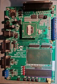
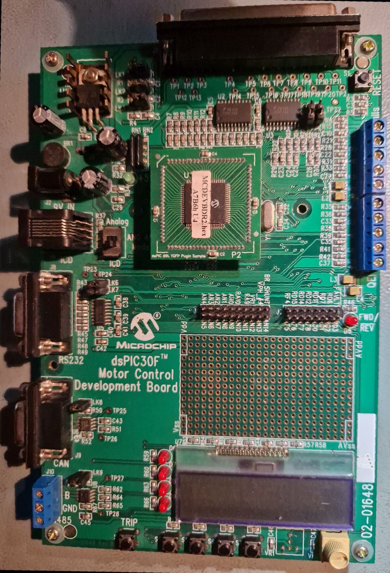
HM2008 Oziloscope ( ist möglich über Service -> Produktservice -> neue Artikel anfragen) Microchip dsPIC30F | | | Microchip PIC 16F883 und 16F886 | Microchip PIC 18F4523 (12/2007: PIC mit 12-Bit A/D-Wandler) * Microchip PIC 18F6585 | Microchip PIC 18F6720 | Microchip PIC 18F8720 | Microchip PIC 24FJ64GB002
entweder einen JLink oder einen XDS110. Auf dem Launchpad ist ein XDS110 quasi mit drauf. Oder halt PIC32EF. Hatte ich ja auch schon mal vorgeschlagen. Wobei ich das eben beruflich mache und auch Boards dafür selber entwickle. Deswegen sind mir 60€ für ein Demoboard auch eher egal, das ist in den Entwicklungskosten
Johannes F. schrieb im Beitrag #7369707: > J. S. schrieb: >> und auch die 5 V Version verträgt höhere Spannungen locker. > > Naja, im Datenblatt steht „bis 1,5 × U_Nenn“, also maximal 7,5 V bei der > 5-V-Version
Johannes F. schrieb im Beitrag #7369994: > Da ich jetzt eh nochmal bestelle, werde ich die SC56-11SURKWA nehmen, > die haben typ. 97 mcd bei 10 mA, also rund das zehnfache. Das sollte > dann auch reichen.
IF system. Transmitters and Receivers 6 . 1 9 1 AGC Response, 3 MOSFET IF (A) 0 0 - — 81 -10 / "W -f J IF A m p •a m / / I Pa t -so / 1 -« / / £ S "50 f •§* -60 O -160 -140 - DO -100 -80 -60 -40 -20 Pi Receiver InputPower, dBm (C) Fig 6.48—Receiver output vs input for a CW receiver. The threshold was
-bit 5.5V, W = 45 µA -0.375 ±0.25 +0.375 LSb 3.0V, I = 24 µA W (Note 7) Capacitance (P ) C — 75 — pF f =1 MHz, Code = Full-Scale A AW Capacitance (Pw) C W — 120 — pF f =1 MHz, Code = Full-Scale Capacitance (PB) C BW — 75 — pF f =1 MHz, Code = Full-Scale Note 1: Resistance is defined as the resistance
-bit 5.5V, W = 45 µA -0.375 ±0.25 +0.375 LSb 3.0V, I = 24 µA W (Note 7) Capacitance (P ) C — 75 — pF f =1 MHz, Code = Full-Scale A AW Capacitance (Pw) C W — 120 — pF f =1 MHz, Code = Full-Scale Capacitance (PB) C BW — 75 — pF f =1 MHz, Code = Full-Scale Note 1: Resistance is defined as the resistance

 Bild
Bild