-
Datei
morse_esp32.ino
(rc + dt); barSetup(fsMeasured); } bool audioBegin() { adc_continuous_handle_cfg_t hcfg = {}; hcfg.max_store_buf_size = 16384; // ~400 ms Reserve, falls loop() aufgehalten wird hcfg.conv_frame_size = 256; // 128 Samples pro Frame if (adc_continuous_new_handle(&hcfg, &adcHandle) != ESP_OK) return false
in „Mit KI generierter CW-Decoder für ESP32“ · Mikrocontroller und Digitale Elektronik ·
-
Thread
TJA1020 mit ESP32 betreiben
Der UART des ESP32 hat einen Hardware-Buffer von 128 Byte und der Library-Default löst bei 120 Bytes einen UART_DATA Event aus, oder nach einer gewissen Timeout-zeit. Ich habe beide Werte etwas nach unten justiert damit ich schneller auf die Daten reagieren
.buffer_len = 0; }; while(1) { if (xQueueReceive(uart_queue, &event, portMAX_DELAY)) { switch (event.type) { case UART_DATA: int len = uart_read_bytes(UART_NUM, rx_buf, event.size, 10 / portTICK_PERIOD_MS
Mikrocontroller und Digitale Elektronik ·Olli Z. · ·50 Antworten
-
Bild
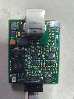
AVRISP mkII Programmiergerät Leiterplatte
AVRISP mkII KYCON 100 M77 61000 HCJ 5A PDIUSB012 74206210 09 bu00811A ATMEL MEGA128 T610A70 355PMZ 625987 MAX4712 EUE
in „Atmel AVRISP MkII, original oder Nachbau?“ · Mikrocontroller und Digitale Elektronik · · Platinenfotos
-
Artikel
AVR-GCC-Tutorial
Wartezeit der Funktion _delay_ms() ist auf 262,14ms/F_CPU (in MHz) begrenzt, d.h. bei 20 MHz kann man nur max. 13,1ms warten. Die Wartezeit der Funktion _delay_us() ist auf 768us/F_CPU (in MHz) begrenzt, d.h. bei 20 MHz kann man nur max. 38,4µs warten. Längere Wartezeiten müssen dann über einen mehrfachen Aufruf
und man muss Daten in anderen Bereichen wie PROGMEM_FAR unterbringen. Auf Controllern mit mehr als 128 KiB Flash bekommen alle Funktionen jenseits 128 KiB ein Trampolin (Sprungbefehl aus 4 Byte) im dem Adressbereich vor 128 KiB. Damit genügt für alle Funktionszeiger 16 Bit. Wird kein Zeiger benötigt,
Artikel ·
-
PDF
Powertip_PE12864LRF-042-H-Q.pdf
) Page3 SAMPLE Ver.01 SPEC Edi.003 1. SPECIFICATIONS 1.1 Features Item Standard Value Display Type 128*64 Dots LCD Type FSTN, Positive,Transflective, Extended Temperature Driver Condition LCD Module:1/65 Duty,1/9 Bias Viewing Direction 6 O’clock Backlight Yellow-Green LED B/L Weight 29.4 g Interface
in „POWERTIP LCD PE12864-003 Anschlussbelegung gesucht“ · Mikrocontroller und Digitale Elektronik ·
-
Bild
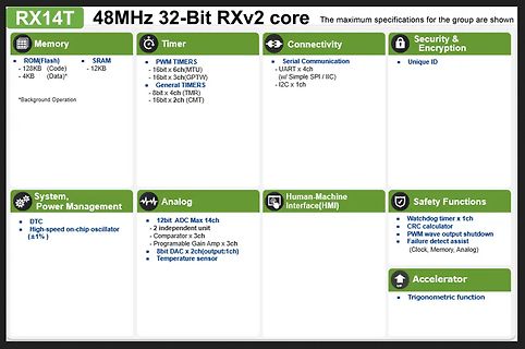
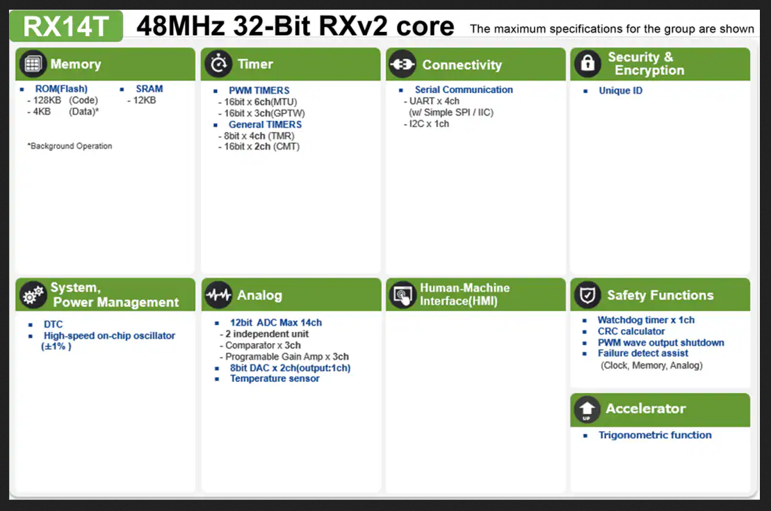
Spezifikationsübersicht RX14T 48MHz 32-Bit RXv2 Core
RX14T 48MHz 32-Bit RXv2 core Memory ROM(Flash) - 128KB (Code) - 4KB (Data)* SRAM - 12KB Timer PWM TIMERS - 16bit x 6ch(MTU) - 16bit x 3ch(GPTW) General TIMERS - 8bit x 4ch (TMR) - 16bit x 2ch (CMT) Connectivity Serial Communication - UART x 4ch (w/ Simple
in „Neue Bauteile: Hochgeschwindigkeitsfunk, Löttechnik und die Rückkehr der QWERTZ-Tastatur“ · Mikrocontroller und Digitale Elektronik · · Screenshots
-
Bild
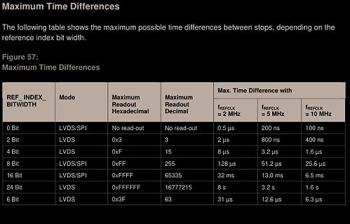
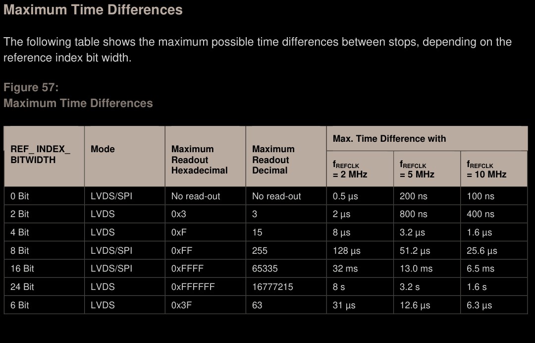
Tabelle der maximalen Zeitdifferenzen zwischen Stopps
Maximum Time Differences REF_INDEX_BITWIDTH Mode Maximum Readout Hexadecimal Maximum Readout Decimal Max. Time Difference with fREFCLK = 2 MHz fREFCLK = 5 MHz fREFCLK = 10 MHz 0 Bit LVDS/SPI No read-out No read-out 0.5 µs 200 ns 100 ns 2 Bit LVDS 0x3 3 2 µs 800 ns 400 ns 4 Bit LVDS 0xF 15 8 µs 3.2 µs 1.6 µs 8 Bit LVDS/SPI 0xFF 255 128 µs 51.2 µs 25.6 µs 16 Bit LVDS/SPI 0xFFFF 65535 32 ms 13.0 ms 6.5 ms 24 Bit LVDS 0xFFFFFF 16777215 8 s 3.2 s 1.6 s 6 Bit LVDS 0x3F 63 31 µs 12.6 µs 6.3 µs
in „TDC(AS6501) als Phasenvergleicher“ · Mikrocontroller und Digitale Elektronik · · Screenshots
-
PDF
l9805e.pdf
. In this MCU, 63742 of these bytes are user accessible. The available memory locations consist of 128 bytes of I/O registers, 256 bytes of RAM, 128 bytes of EEPROM and 16Kbytes of user EPROM/ROM. The RAM space includes 64 bytes for the stack from 0140h to 017Fh. The highest address bytes contain the
in „ST L9805-E Motortreiber mit H Brücke und ST7UD05 Kern“ · Mikrocontroller und Digitale Elektronik ·
-
Bild
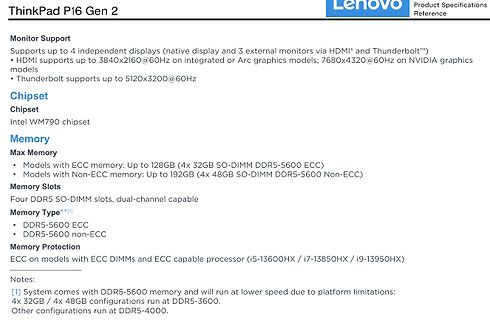
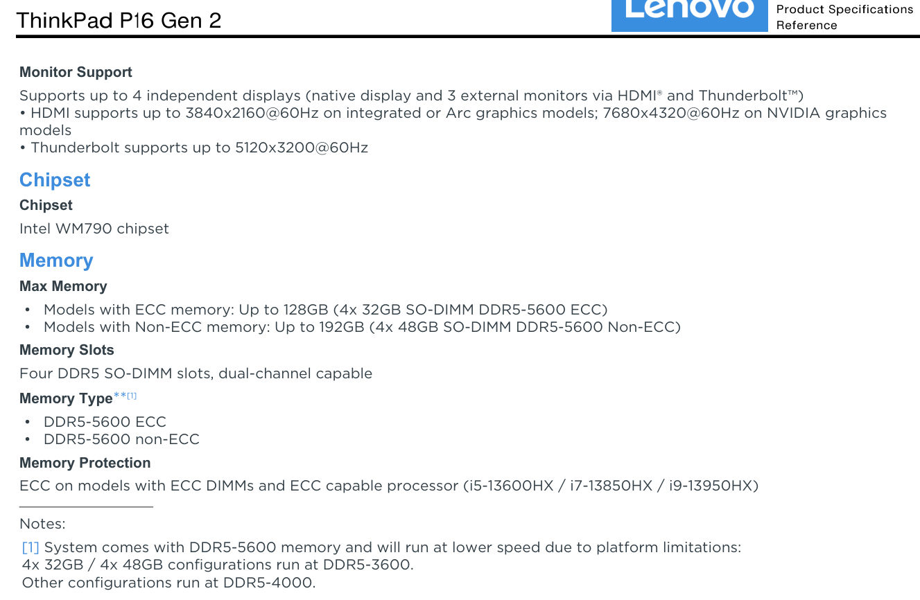
Produktspezifikationen ThinkPad P16 Gen 2
NVIDIA graphics models • Thunderbolt supports up to 5120x3200@60Hz Chipset Intel WM790 chipset Memory Max Memory • Models with ECC memory: Up to 128GB (4x 32GB SO-DIMM DDR5-5600 ECC) • Models with Non-ECC memory: Up to 192GB (4x 48GB SO-DIMM DDR5-5600 Non-ECC) Memory Slots Four DDR5 SO-DIMM slots, dual-channel
in „Lenovo ThinkPad-P16-G2 - RAM erweitern von 64 auf 128 GB“ · PC Hard- und Software · · Screenshots
-
Datei
Neuron.vhd
11; --Weight Memory Size DATA_WIDTH : integer := 16; --Float16 Format PAGE_WIDTH : integer := 4; --max. 16 Layers INPUT_WIDTH : integer := 7; --max 128 Input Signals INPUTS : integer := 10; --Number of used inputs LATENCY : integer := 6); Port ( --Control Signals clk : in std_logic; reset : in std_logic
in „Pipeline MAC-Unit: Problem mit Latency“ · FPGA, VHDL & Co. ·
-
Datei
Neuron.vhd
11; --Weight Memory Size DATA_WIDTH : integer := 16; --Float16 Format PAGE_WIDTH : integer := 4; --max. 16 Layers INPUT_WIDTH : integer := 7; --max 128 Input Signals INPUTS : integer := 10; --Number of used inputs MULT_LATENCY : integer := 6; --make shure: Latency < inputs! ADD_LATENCY : integer := 6
in „Pipeline MAC-Unit: Problem mit Latency“ · FPGA, VHDL & Co. ·
-
PDF
PCF7936AS.pdf
No additional battery supply is needed. Data is transmitted • 256 bit EEPROM for user data storage (128 bit) and by modulating the LF field. device configuration/personalization (128 bit) • EEPROM read/write protection features The Security Transponder features secure contactless • 20 years non-volatile
-
Datei
CoolTerm_Capture__FritzAVM_1V8.CoolTermSettings__2026-06-27_08-52-21-633.txt
size: 131072 bytes (128 KiB), LEB size: 126976 bytes [ 4.612434][ T1] ubi0: min./max. I/O unit sizes: 2048/2048, sub-page size 2048 [ 4.620079][ T1] ubi0: VID header offset: 2048 (aligned 2048), data offset: 4096 [ 4.627630
in „FRITZ!Box 7490 Bootloop“ · Mikrocontroller und Digitale Elektronik ·
-
PDF
Anleitung-Eurolite-SL-1200-search-light-de_en_es_fr.pdf
Percentage S/F Eigenschaft 0 255 00 FF 0% 100% F Allmähliche Einstellung des Durchmessers von Min. nach Max. Steuerkanal 2 - Farbrad 1 Lineare Farbänderung gemäß der Bewegung des Reglers. Sie können den Farbwechsler an jeder gewünschten Position anhalten. Zwischen 128 und 255 dreht sich der Farbwechsler ständig
in „Eurolite SL-1200: Thermische Abschaltung nach 10 min (HMI-Lampe)“ · Analoge Elektronik und Schaltungstechnik ·
-
Datei
Neuron.vhd
11; --Weight Memory Size DATA_WIDTH : integer := 16; --Float16 Format PAGE_WIDTH : integer := 4; --max. 16 Layers INPUT_WIDTH : integer := 7; --max 128 Input Signals INPUTS : integer := 10; --Number of used inputs MULT_LATENCY : integer := 6; --make shure: Latency < inputs! ADD_LATENCY : integer := 6
in „Pipeline MAC-Unit: Problem mit Latency“ · FPGA, VHDL & Co. ·
-
PDF
2S-0830-V1-2.pdf
detection voltage V DET2 2.0±0.075V Over discharge protection tV DET2 Over discharge detection delay time 128±39ms Over discharge release voltage V REL2 2.5±0.08V V DET3 Over current detection voltage 0.2±0.015V Over current detection current IDP 7.0-12.0A Over current protection Detection delay time tV DET3
in „akkupack litium Ionen 2S2P 3AH für Handfunkgerät Icom IC2E“ · Analoge Elektronik und Schaltungstechnik ·
-
Datei
MSP3400_ATMEGA32_ADC_2.ino
; bool lastAV = false; unsigned long memoryPulseUntil = 0; // PWM-DAC Regelung uint8_t pwm1Value = 128; // PB3 uint8_t pwm2Value = 128; // PD7 const uint16_t targetADC = 511; const uint8_t pwmStep = 2; bool isAV() { return (program == 17); } // --------------------------------------------------------
in „Zeigt her eure Kunstwerke (ab 2023)“ · Projekte & Code ·
-
Datei
MSP3400_ATMEGA32_ADC_2.ino
; bool lastAV = false; unsigned long memoryPulseUntil = 0; // PWM-DAC Regelung uint8_t pwm1Value = 128; // PB3 uint8_t pwm2Value = 128; // PD7 const uint16_t targetADC = 511; const uint8_t pwmStep = 2; bool isAV() { return (program == 17); } // --------------------------------------------------------
in „AUDIOCONTROLLER MSP3400C einfach mit ATMEGA32 ansteuern“ · Projekte & Code ·
-
PDF
40146F.pdf
0°C to +70°C Industrial(I):Tamb = -40°C to BSEL = 0 BSEL = 1 +85°C Symbol Characteristic Min Typ. Max. Min. Typ. Max. Units TE Basic pulse element 260 400 620 130 200 310 μs TBP PWM bit pulse width 3 3 TE TP Preamble duration 28 28 TE TS Sync Pulse duration 10 10 TE TH Header duration 10 10 TE THOP
in „Fehlersuche Funksender Zentralverriegelung Toyota Yaris“ · Fahrzeugelektronik ·
-
Datei
main.cpp
static constexpr int LED_PIN = 8; static constexpr int LED_COUNT = 1; static constexpr uint8_t LED_MAX_BRIGHTNESS = 200; #if LED_TYPE == 0 // Classic SuperMini blue LED is active-low (LOW = on). We drive brightness // via LEDC PWM on this channel. static constexpr bool LED_ACTIVE_LOW = true; static constexpr
-
Datei
philipsPM-LCDs.txt
Das PM2521 verwendet drei LCD-Treiber SAA1062:Seite 56 (54/187) 1.4.6. Display section (Seite 136 (128/187)) Seite 89 (84/187): 5.3. Front Assembly: LCD (L.C. display 5322 130 94033 (532213094033) interconnection rubber 5322 290 84029 (532229084029) Display unit N3 5322 216 74066 (532221674066) Seite
in „Pjilips PM2519“ · Markt ·
-
PDF
Stenorette_2010_SW.pdf
Kopfspiegef an der Lehre anliegt, dund sor dern- gentstärkeregfer an Kgemessen. (Steckerleiste) ge- max. Abstand von 0,1 mm eingehalten uird. lvlassnach lvlS1 Uiedergabe-Pegelkontrolle bei geschlossenem Deckel uiederho.Ien. b) Kopfhöhe Der AIJL-Kopf uird mit der gleichen Lehre so ein- gestellt, daß die
in „Recht auf Reparatur“ · Offtopic ·
-
PDF
Motorola_MC44353_MC44354_MC44355_1998.pdf
0.006) T U S 7 DIMENSIONAANDBARETOBEDETERMINED M ATDATUMPLANE–W–. A MILLIMETERS INCHES –V– DIM MIN MAX MIN MAX N A 6.40 6.60 0.252 0.260 B 4.30 4.50 0.169 0.177 C ––– 1.20 ––– 0.047 F D 0.05 0.15 0.002 0.006 DETAIL E F 0.50 0.75 0.020 0.030 C G 0.65BSC 0.026BSC H 0.27 0.37 0.011 0.015 J 0.09 0.20 0.004
in „Pollin ist pleite :-(“ · Offtopic ·
-
PDF
DM8203.pdf
thereceivedCRCerrorpacketalsoacceptstoreceivememory. 1:0 AGE PE0,RW AddressTableAging 00:noaging 01:64±32sec 10:128±64sec 11:256±128sec 6.8 VLAN Control Register (53H) Bit Name Default Description 7 TOS6 PE0,RW FullIPToSFieldforPriorityQueue 1:checkmostsignificant6-bitofTOS 0:checkmostsignificant3-bitonlyofTOS 6
in „[V] DM8203 & DM8603“ · Markt ·
-
Datei
ESP8266_WiFI_UDP_Server_OLED.ino
pointer Adafruit_SSD1306 *display; // Buffer for incoming UDP messages char udp_buffer[WIFICLIENT_MAX_PACKET_SIZE+1]; volatile uint16_t seconds = 0; volatile uint16_t newmsg = 0; // flag to display new message volatile uint32_t led_on = 0; // LED on time uint8_t newMACAddress[] = {0x00, 0x90, 0xB7,
in „UDP-Netzwerke(l)n mit kleinen Mikrocontrollern und WizNet W5100/W5500“ · Mikrocontroller und Digitale Elektronik ·
-
PDF
M48T58Y.pdf
parameters M48T58, M48T58Y Table 10. Power down/up AC characteristics (1) Symbol Parameter Min Max Unit tPD E1 or W at VIHor E2 at ILbefore power down 0 µs (2) tF VPFD (max) to VPFD (min) VCC fall time 300 µs (3) M48T58 10 µs tFB VPFD (min) to SS V CC fall time M48T58Y 10 µs t V (min) to V (max) V rise time 10 µs R PFD PFD CC t V to V (min) V rise time 1 µs RB SS PFD CC trec VPFD (max) to inputs recognized 40 200 ms 1. Valid for ambient operating temperaAure: T = 0 toCC0= 4.75 to 5.5 V or 4.5 to 5.5 V (except where noted). 2. V PFD(max) to PFD(min) fall time of lessFthan t may result
in „[S] DALLAS DS1220Y-150 NVRAM (NOS)“ · Analoge Elektronik und Schaltungstechnik ·
-
PDF
TinyBasic_Pro_-_BASIC.pdf
-------------------------------------- AOUT pin,value Outputs an analog/PWM value. Example: AOUT 0,128 AVR TinyBasic Pro © 2026 D. Kristen - 13 – SD CARD COMMANDS ======================================================================================= DIR Displays directory contents. -----------------
in „AVR Tiny Basic Computer mit ATMega1284“ · Projekte & Code ·
-
PDF
am79c961.pdf
External Clock 5 ns Notes: 1. DI pulses narrower thanPWODI (min) will be rejected; pulses wider PWODIt(max) will turn internal DI carrier sense on. 2. DI pulses narrower thanPWKDI (min) will maintain internal DI carrier sense on; pulses widPWKDIa(max) will turn internal DI carrier sense off. 3. CI pulses narrower thanPWOCI (min) will be rejected; pulses wider PWOCIt(max) will turn internal CI carrier sense on. 4. CI pulses narrower thanPWKCI (min) will maintain internal CI carrier sense on; pulses widPWKCIa(max) will turn internal CI carrier sense off. Am79C961 1597
-
PDF
moxa-awk-3131a-series-datasheet.pdf
5.320 GHz (4 channels) 3 5.500 to 5.700 GHz (11 channels) Wireless Security WEP encryption (64-bit and 128-bit) WPA/WPA2-Enterprise (IEEE 802.1X/RADIUS, TKIP, AES) WPA/WPA2-Personal Wireless Roaming Turbo Roaming 4 Transmission Rate 2.4 GHz: Up to 144.4 Mbps 5 GHz: Up to 300 Mbps Transmitter Power US EU
in „[V] Diverse Moxa Industrie Switche und Access Points“ · Markt ·
-
PDF
asus-p701-unlocked.pdf
ACOK# 3 1 Vcls=3.413V GND K U 2 2 G1 N D1 7 2 1 1 MAX8724_REF MAX8724_LDO 5 0 2 T PR9 MAX8724_LDO PL1 PR8 /X S G PR12 7 1 S BAT_LX_20mil 3 S2 D2 6 1 2 1 2 BAT 2 PQ7 10KOhm _ 2 1 0 2N7002 GND 1 A 2 4 G2 N D2 5 2 S 6.2UH 2 25mOHM E 5 /X GND B 33Ohm 1 Irat
-
PDF
217369.pdf
Phosphor bronze .052 2 or beryllium copper with [1.32]yp. 8 5 tin or gold plating (see table) .015 .210 Max. ) [.381]yp. [5.33] 0 A 8 : e .128±.007 A [3.25±.178] l .150±.004 .150±.004 c [3.81±.102] [3.81±.102] L C e [0.58±.051]p. i u .048 O .100±.008 [1.22] Sockets with Straight Solder Tails [2.54±.203]yp
in „Kühlkörper TO3 Befestigungslöcher zu groß?“ · Mechanik, Gehäuse, Werkzeug ·
-
PDF
TF5000CI.pdf
, 16K) Write Modes Serial EEPROM • Partial Page Writes Are Allowed • Self-Timed Write Cycle (10 ms max) 1K (128 x 8) • High Reliability – Endurance: 1 Million Write Cycles 2K (256 x 8) – Data Retention: 100 Years – ESD Protection: >3000V 4K (512 x 8) • Automotive Grade and Extended Temperature Devices
in „CPU SAA7219 per Jtag auf Basis FT2232H ansprechen - Tool schreiben“ · PC Hard- und Software ·
-
PDF
S32K-RM.pdf
Statistic Register (ENET_RMON_R_P65TO127)...........................................2055 57.5.74 Rx 128- to 255-Byte Packets Statistic Register (ENET_RMON_R_P128TO255).......................................2055 57.5.75 Rx 256- to 511-Byte Packets Statistic Register (ENET_RMON_R_P256TO511).............
-
PDF
grip1.pdf
768x280 oder 768x560 Bildpunkten. Sie wird durch Vektor-Zeichenbefehle unterstützt. Farbgrafik (16 oder 128 frei definierbare Farben pro Bild- punkt) ist mit der Zusatzkarte GRIP-COLOR möglich. Davon abgesehen läßt sich die Karte wie ein normales Text-Terminal einsetzen. Sie enhält im Text-Modus 9 verschiedene
in „Conitec PROF-80 Informationsseite“ · Mikrocontroller und Digitale Elektronik ·
-
PDF
dm9161-ds-f05_091008.pdf
FastEthernetPhysicalLayer TX/FXSingleChipTransceiver 9.4.2Oscillator/CrystalTiming Symbol Parameter Min. Typ. Max. Unit Conditions tCKC OSCCycleTime 39.998 40 40.002 ns 50ppm tPWH OSCPulseWidthHigh 16 20 24 ns tPWL OSCPulseWidthLow 16 20 24 ns 9.4.3 MDC/MDIO Timing Symbol Parameter Min. Typ. Max. Unit Conditions
in „Beschaltung VICOM DM9161CEP“ · Mikrocontroller und Digitale Elektronik ·
-
PDF
Sinuswechselrichter.pdf
jedem der sieben untersuchten Geräte ergab sich ein Mittelwert x extrem , der im Bereich von 126 bis 128 liegt. Aufgrund der begrenzten Anzahl an untersuchten Geräten ist es aber nicht ausgeschlossen, dass das Intervall größer sein kann. Um diesen Mittelwert herum bilden je acht Werte die positive und
in „Wechselrichter Spannung und Frequenz steuerbar für Teichpumpe“ · Haus & Smart Home ·
-
PDF
DM8603EP.pdf
portEthernetSwitchControllerwithMII/RMIIInterface 10.4.4 Port 2 RMII Interface Transmit Timing Symbol Parameter Min. Typ. Max. Unit T1 RMII REF_CLK Period - 20 - ns T2 P2_TXE,P2_TXD1~0 to REF_CLK 8 ns Rising Output Delay 10.4.5 Port 2 RMII Interface Receive Timing Symbol Parameter Min. Typ. Max. Unit T1 RMII REF_CLK Period
in „[V] DM8203 & DM8603“ · Markt ·
-
Datei
DESKTOP-D15LMP4.html
Number of cores</small></td><td valign="center"><small><font color="#0000A0">6 (max 6)</font></small></td></tr> <tr valign="top" bgcolor="#FFFFFF"><td width="300"><small> Number of threads</small></td><td valign="center"><small><font color="#0000A0">12 (max
-
PDF
moxa-awk-1137c-series-datasheet.pdf
5.320 GHz (4 channels) 5.500 to 5.700 GHz (11 channels) Wireless Security WEP encryption (64-bit and 128-bit) WPA/WPA2-Enterprise (IEEE 802.1X/RADIUS, TKIP, AES) WPA/WPA2-Personal 4 Wireless Roaming Turbo Roaming Transmission Rate 2.4 GHz: Up to 144.4 Mbps 5 GHz: Up to 300 Mbps Transmitter Power US EU
in „[V] Diverse Moxa Industrie Switche und Access Points“ · Markt ·
-
PDF
ONJU_Schematic.pdf
IO2) GND GND GPIO46 IP 50 PIU307/HOLD/RESET(IO3) GND GND GND IP750 GND PIU304 GND GND ESP32-S3R8 W25Q128JVSIQ GND GND Microphones QSPI NOR Flash GND ESP32-S3 U2OC 5V 7 P VDD 8 702UIP CO26 SCK 16 VDD 802UIP 220 pF J44JOC 6BCLKIP WS PI2014LRCLK OUTN PU200 MA _SPK_NPS P SPK_N PIJ01 1 3V3 R28 NSO PIU21 DIN
in „Bitte um Review meiner erweiterten ONYU-Schaltpläne (Bluetooth-Erweiterung mit CSR8635)“ · Mikrocontroller und Digitale Elektronik ·
-
PDF
pm2519ocr.pdf
button “zero set on/off” 1.6. D C C U R R E N T M E A S U R E M E N T S Ranges :20mA,20mA,2.4,208 (max, input current in highest range) #10 A (20 A for max, 20 sec.) Resolution 510HAin20mArange Number of representation units £2200 Acuracy ++(0.5%ofreading+0.1%offulscale) Temperature coefficient +0.05%
in „Pjilips PM2519“ · Markt ·
-
PDF
GPS-Compendium_Book__GPS-X-02007_.pdf
.................................................................................................. 128 7.8.4 Correlators and correlation time................................................................................................ 128 7.9 GNSS-repeater or re-radiation antenna..................
in „Verschlüsselte Militär(?)daten innerhalb des GPS-Signals“ · HF, Funk und Felder ·
-
PDF
Sartorius_Waage_Manual_Anleitung_Handbuch_QC7DCE-S.pdf
/i key + print information: p/p key + Target weight z/T key Set Setp Min weight value S – min Max weight value S + max Tolerance ranges when values entered via keypad: or Delta min d – d min Delta max d + d max Numeric entry: Numeric keys 0–9 Enter parameters and . + z/T key for “Weight” Target
in „Frage zu einer Waage / Sartorius QC7DCE-S“ · Mechanik, Gehäuse, Werkzeug ·
-
PDF
W5500_ds_v110e.pdf
Version1.1.0 59 / 67 5.4 Power Dissipation (Test Condition: VDD=3.3V, AVDD=3.3V, Ta = 25°C) Condition Min Typ Max Unit 100M Link - 128 - mA 10M Link - 75 - mA Un-Link(Auto-negotiation mode) - 65 - mA 100M Transmitting - 132 - mA 10M Transmitting - 79 - mA Power Down mode - 13 - mA 5.5 AC Characteristics 5.5.1 Reset
in „Schaltung W5500“ · Mikrocontroller und Digitale Elektronik ·
-
PDF
PCA9532.pdf
--------------------- 152 PSC0 = 151 Set PWM0 duty cycle to 50 %: 80h PWM0 --256----------- PWM0 = 128 Set prescaler PCS1 to dim at maximum frequency: 00h Blink period = max PSC1 = 0 Set PWM1 output duty cycle to 25 %: 40h PWM1 ---------------- 256 PWM1 = 64 Set LED0 to LED3 on 55h Set LED4 and LED5
in „[V] 10St. SMD 16-bit LED I2C Treiber NXP_PCA9532PW.112 (TSSOP24) (10€)“ · Markt ·
-
PDF
slaa323a.pdf
Incorporated www.ti.com Resolution of an ADC SNR (dB) = (6.02 × N) + 1.76 + 10 × lo10(k) where • k = s / (2 max) • f is the sampling frequency s • 2 × maxis the Nyquist frequency (3) Figure 1 shows the signal flow diagram for the oversampling method. The quantization noise is modeled as white noise that is additive
-
Artikel
WordClock mit WS2812
Save-Schaltfläche. Die automatische Helligkeitssteuerung verwendet dann bei einer Helligkeitsmessung diese Min-/Max-Werte zum Vergleich. Somit kann der Helligkeitsbereich bei der automatischen Helligkeitssteuerung komplett ausgenutzt werden. Hinweis: Es ist nicht sinnvoll, bei der Max-Messung einfach eine Taschenlampe
bestimmten Anzeigemodi. Bugfix SK6812: Rot und Grün vertauscht. Bugfix LDR: Nach dem Setzen eines neuen LDR-Max-Wertes wurde dieser nicht zurück an das Web-Interface übertragen und deshalb dort (bis zum nächsten Reboot) ein alter Max-Wert angezeigt. STM32 Version 2.1.0. Auslagerung des HTML-Codegenerators auf
Artikel ·
-
PDF
PCF7922ATT.pdf
Prescaler Ratio Note Figure 24. 0 0 0 256 The watchdog timer is always active when the device 0 0 1 128 operates in BATTERY mode (PMODE = 1). 0 1 0 64 When the watchdog is not continuously restarted and 0 1 1 32 allowed to timeout, it will force the Supply Switch logic to 1 0 0 16 open the Supply Switch
-
PDF
Datasheet_MFRC522.pdf
between pins TX1 and TX2 at 13.56 MHz. [7] DD(SVDD)depends on the load at pin MFOUT. Vmod V V i(p-p)(max) i(p-p)(min) VMID 13.56 MHz carrier 0 V 001aak012 Fig 24. Pin RX input voltage range 14.1 Timing characteristics Table 154. SPI timing characteristics Symbol Parameter Conditions Min Typ Max Unit WL
in „IRQ am RFID RC522“ · Mikrocontroller und Digitale Elektronik ·
-
PDF
KEM_F3093_R46_X2_275_110C.pdf
Recommendations Following is the recommendation for manual 300 soldering with a soldering iron. 260°C 2+3seconds max 250 First Wave Second Wave Recommended Soldering Temperature 400 )00 ( ∆ T < 150°C 350 r Cooling t C r50 Preheating ca. 2°C/second e 300 p ca. 3.5°C/second typical t e ca. 5°C/second e 250 100 T preheat
in „Staubsauger AEG VX8.2 schaltet sich immer wieder aus (Lösung)“ · Haus & Smart Home ·