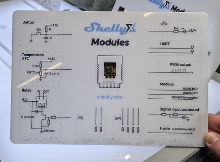
Shelly Modules
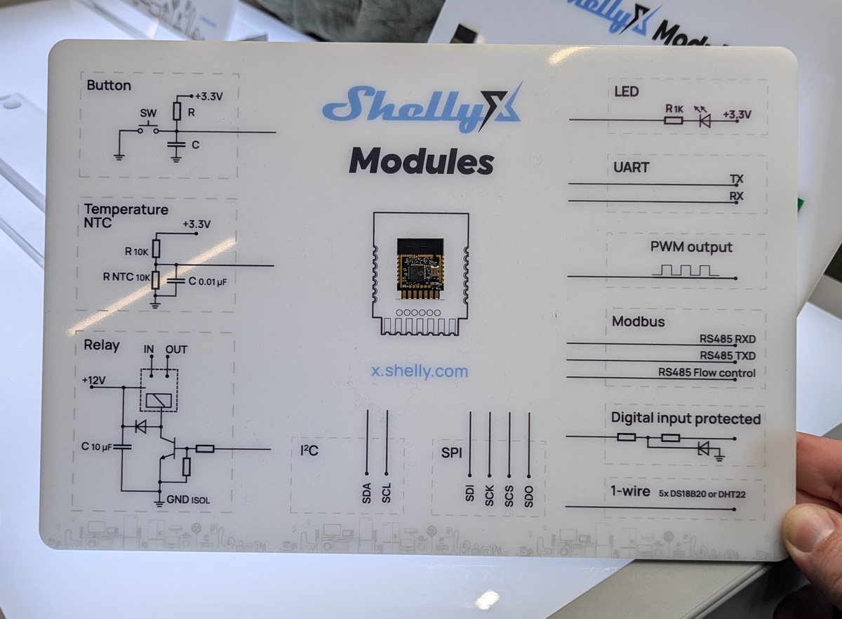
Button
SW
+3.3V
R
C
LED
R 1K
+3.3V
UART
TX
RX
Temperature NTC
+3.3V
R 10K
R NTC 10K
C 0.01 µF
PWM output
Modbus
RS485 RXD
RS485 TXD
RS485 Flow control
Relay
IN
OUT
+12V
C 10 µF
I2C
SDA
SCL
Digital input protected
SPI
SDI
SCK
SCS
SDO
1-wire
5x DS18B20
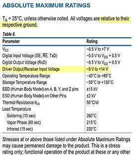
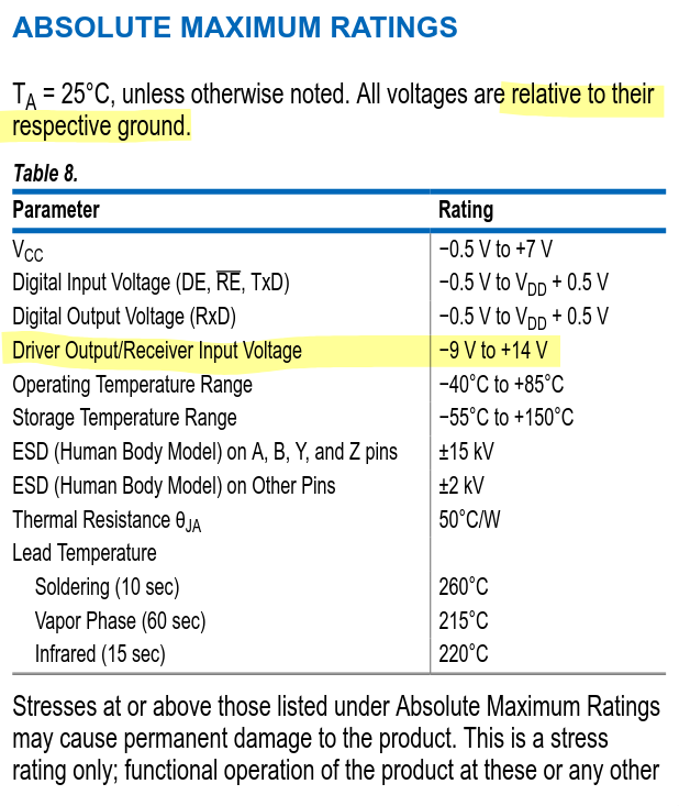
VCC -0.5 V to +7 V
Digital Input Voltage (DE, RE, TxD) -0.5 V to VDD + 0.5 V
Digital Output Voltage (RxD) -0.5 V to VDD + 0.5 V
Driver Output/Receiver Input Voltage -9 V to +14 V
Operating Temperature Range -40°C to +85°C
Storage Temperature Range -55°C to +150°C
ESD (Human Body Model) on A, B, Y, and Z pins ±15 kV
ESD (Human Body Model) on Other Pins ±2 kV
Thermal Resistance θJA 50°C/W
Lead Temperature
Soldering (10 sec) 260°C
Vapor Phase (60 sec) 215°C
Infrared (15 sec) 220°C
Nullmodem-Kabel!), das an den seriellen Port des PCs angeschlossen wird. Bei einem Modem-Kabel sind die Pins 2 und 3 des einen Kabelendes mit den Pins 2 und 3 des anderen Kabelendes durchverbunden. Bei einem Nullmodem-Kabel sind die Leitungen gekreuzt, sodass Pin 2 von der einen Seite mit Pin 3 auf der anderen
passieren, dass die Situation eintritt, dass das empfangende Gerät nicht mehr mitkommt. Das kann z. B. dadurch passieren, dass das empfangende Gerät selbst etwas Zeit für die Bearbeitung der Daten benötigt. Man denke z. B. an die Situation, dass an ein Modem Daten übertragen werden. Das Modem muss diese
Motorlauf • Kompakte Größe • Eingangssignal: Puls / Richtung (PUL/DIR) • Bandbreite Current Loop:(-3dB)2KHz (Typisch) • Bandbreite Speed Loop: 500Hz (Typisch) • Bandbreite Position Loop: 200Hz (Typisch) • Parameter können via RS232 zum PC übertragen werden. • Einstellungen über DIP-Schalter oder Software
at === NXP LPC23xx === Mikrocontroller mit ARM7TDMI-S-Kern (vgl. LPC2000 Philips ARM7TDMI-Familie) 2 CAN Schnittstellen NXP P80C591 P80C592 P80C598. 8-Bit Mikrocontroller mit 8051-Kern P80C591 ist neuer und beherrscht CAN2.0B P80C592: CAN2.0A, P80C598 ist die Automotive-Version vom '592 Silicon Labs
. 2 ) Links. Ansteuerung eines MCP2515 in C Bit Timing Calculator für Linux Eagle Bauteil SJA1000. CAN-Controller von Philips Parallele Schnittstelle mit ca. 12 Leitungen erhältlich z. B. bei Reichelt (ca
band 2.4G Transmitting power Max 12db Working temperature -40℃ - 80℃ Receiving sensitivity -96db Transmission distance 160m Working voltage 2.2V-3.6V TX current 40mA RX current 24mA Sleep current 10uA Communication
0 1 t l : e h 2 r z 2 h n 1 1 U e n - t g m a a t W p ) 2 y = m e o S - e h o e ( d d ( o r C l e t u L e b c 2 1 1 | 1 I a L M s i e 8 s B e d t Z m n o e n t e f - - t Cd >>s b CÖu -Hx Xi Wt *ü J t/1 ,H rH C •H o
den entsprechenden Anschluss auf Ausgang schalten, werden mit DDRB=0xff alle Anschlüsse des Ports B als Ausgänge eingestellt. Die den ersten beiden Bits des Ports zugeordneten Anschlüsse (PB0 und PB1) werden 1, alle anderen Anschlüsse des Ports B (PB2-PB7) zu 0. Aktivierte Ausgänge (logisch 1 oder
. + Logikpegel VCC [V] Low [V] High [V] 5 1,0 3,5 3,3 0,66 2,3 1,8 0,36 1,26 Die Abfrage der Zustände der Portpins erfolgt direkt über den Registernamen. Will man also die aktuellen Signalzustände von Port D abfragen und in eine Variable namens bPortD abspeichern
and very low noise • Compact size • Pulse Input Mode Pulse + Direction • Current Loop Bandwidth:(-3dB)2KHz (Typical) • Speed Loop Bandwidth: 500Hz (Typical) • Position Loop Bandwidth: 200Hz (Typical) • Parameters to download via RS232 to PC. • Users can define subdivisions via external Dial-up switches
), r(ight), o(up), u(down). R L x1,y1,x2,y2 are the surrounding rectangle of the bar. aw,ew are no barlues fo Define bargraph ESC B O n1 x1 y1 x2 y2 aw ew type pat 0% and 100%. defined U type=0:pattern bar; type=1:pattern bar in rectangle;
number Example: AT+VERSION\r\n +BOLUTEK Firmware V2.2, Bluetooth V2.1, HCI V2.1, HCI Rev37, LMPV4, LMP SubV37 TEL:86-0755-26509941 WEB:www.bolutek.com Page 2 of 21 BOLUTEK BLK-MD-BC04-B BLUETOOTH MODULE AT COMMANDS Command 3: Inquires the help informations
R712 7 R720 Q681 0 1 4.USBD+ C C 4.USBD+ 3 R721 5.DGND 1 1 5.DGND . . . . . 2 S S S L L G G V V V N N V V V N N 3 3 0 0 R R D D S S S 2 C . . . . . C C C C 6 6 W W W 1 2 3 4 5 BasicConnector R663 9 2 AC INLET (A SIDE) AC INLET (B SIDE) CN90 9 X L FH92 C L RX92 RX91 CUP12674Z-3
2 GND B A 2 B A 2 B A 2 B A 2 B A 2 B A 21 2 B A B A B A B A 17 1 B A 1 1 1 1 1 1 1 1 1 1 B A 1 1 1 1 1 1 1 1 1 1 B A 1 1 1 1 1 1 1 1 1 1 A 1 A 1 1 1 1 1 1 1 1 1 1 1 1 1 1 1 1 1 1 1 A A Y A A Y A A Y A
B TOTX197 TORX198 (2) TOCP100 - BTOCP100P - B DC to 6 670 Up to 40 ±55 5± 0.25 – 40 to 85 APF (980/1000) TOCP155- BTOCP155P- B TOTX170A (3)TORX170 TOCP100- BTOCP100P- B DC to 6 650 Up to 40 ±55 5± 0.25
res; dali G de E 8 2 #y| s E 8 8 y B E E R 83) 8 5 8 2 3 = Ea a B i s = G ¢: é g |e 3 8 a4. P A R T B t we l eow u|e e |¢ £e u£ ~ 2 2 |2 (2 2 |2 3 = i e fe [ le 2 6 ls eS 5g & B l a |8 B [8 4 a g 2 | 2 2] 2 |g g| ¢ & B E
tro lle(H o d u lfrag en ) 0 ,4 M eßprotokolle 0 ,3 Funktion 0 ,3 1 ,0 1! - N E T Z E I N S C H U B R E G E L B A R 2 .1 1 . 0 Busbelegung: S t i f t Nr. b e le g m it 1 + 1 ,5 V / 1 ,0 A s t a b i l 2 + 17 V / 2 ,0 A g e s ie b t 3 + 12 V / 1 ,0 A s t a b i l 4 - 12 V / 1 ,0 A s t a b i l 5 0 - P
) Abatron BDI1000 & BDI2000, On-Chip Debuggers für ARM, 68k, Coldfire uvm. Amontec JTAGkey, JTAGkey2(P): JTAG-Adapter auf Basis des FTDI2232(H) H-JTAG USB Emulator Keil/ARM ULINK/ULINK2/ULINK-ME JTAG-Adapter, USB-Anschluss, wird von Keil uVision unterstützt, ULINK2 teilw. auch von Codesourcery G++ (
sehr schneller Echtzeitkernel unter anderem für ARM7 (Philips LPC2106/LPC21XX/LPC22xx, Samsung S3C44B0X, Atmel AT91SAM7S128, STMicroelectronics STR711FR2) uC/OS-II RTOS Hardware (Prototypen-Platinen etc.). <!-- Veralteter Link; Shop verkauft "nichts" mehr * KNIF-elektronik Preisgünstige Industriemodule
time 1 at which VIHis reached satisfies to V(t1) = 0.3 x DD = VDD x (1 – e(1t / PU b )) leading to t = 0.3566749 x R x C 1 PU b 3. With V OH = 0.7 x VDD , the time 2 at which VOH is reached satisfies to V(t ) = 0.7 x V = V x (1 – e(-t / R C )) 2 DD DD 2 PU b leading to 2 = 1.2039729 x R PU x Cb 4. With tr= t2- 1 , it comes t = 0.8473 x R x C r PU b 5.2 Three-volt tolerant and five-volt tolerant Electrical characteristics defines GPIO as three-volt tolerant, five-volt tolerant, and also three-volt capable.
5 6 7 8 9 0 1 2 3 4 5 6 7 8 9 0 1 2 3 4 5 6 7 8 9 0 1 2 3 4 5 6 3 3 3 3 3 3 4 4 4 4 4 4 4 4 4 4 5 5 5 5 5 5 5 5 5 5 6 6 6 6 6 6 6 4 2 3 4 5 7 3 4 5 E N Y R 1 5 2 1 5 0 6 M 3 4 5 F 2 E M R 9 T D B B B B S A A A W E D
’ = a•X2 + b•Y2 + c [II Y2’ = d•X2 + e•Y2 + f X3’ = a•X3 + b•Y3 + c Y3’ = d•X3 + e•Y3 + f Equation [II] is then represented in the matrix form X 1' X 1 Y1 1 0 0 0 a Y 1' 0 0 0 X1 Y1 1 b
Bandwidth Mode) 10 Hz to 20 kHz 20 to 70 kHz 70 to 80 kHz Inputs >1 mV (–57.8dBu) to10mV (–37.8dBu) ±1.0 dB ±1.0 dB ±2.0 dB Input >10 mV (–37.8 dBu) to 1.946 V (+8 dBu) ±0.15 dB ±0.2 dB ±1.0 dB (Typically ±0.05 dB from 50 Hz to10 kHz) Input >1.946 V (+8 dBu) to < 64 V (+36 dBu) for ±0.20 dB ±0.25 dB ±1.0 dB

 Bild
Bild
 Bild
Bild
 Bild
Bild