offer high resolution with independent time platform that simplifies design and helps eliminate many bases to help simplify drive control. discrete components in power conversion systems. This family includes the Programmable Ramp Generator (PRG) Complementary Output Generator (COG) peripheral which eliminates
force table actuator travel 0.15 0.25 0.35 mm operating temperature -30 80 °C storage temperature -40 90 °C rated load, 2 cycles/second, 1.5 times operating force 100 gf models 100,000 cycles life 160 gf models 80,000 cycles 260 gf models 60,000 cycles vibration 10~55~10 Hz, 1.5 mm amplitude, 2 hours
dBm) RX Range (dBm) -3 to -32 Optical Power Link Budget (dB) 12 Dispersion 3 3 3 3 Penalty (dB) 100BaseFX Multi-Mode Single-Mode 50/125 µm Fiber Cable Type G.652 800 MHz x km Typical Distance 5 km 40 km TX Range 1260 to 1360 1280 to 1340 (nm) Wavelength RX Range 1100 to 1600 1100 to 1600 (nm) TX Range
Standards IEEE 802.3 for 10BaseT IEEE 802.3u for 100BaseT(X) IEEE 802.3ab for 1000BaseT(X) IEEE 802.3at for PoE IEEE 802.1Q for VLAN Tagging IEEE 802.1X for authentication IEEE 802.1D-2004 for Spanning Tree Protocol IEEE 802.1w for
Class of Service IEEE 802.3x for flow control IEEE 802.3ad for Port Trunk with LACP Optical Fiber 100BaseFX Multi-Mode Single-Mode Single-Mode (40 km) (80 km) 50/125 µm Fiber Cable Type OM1 G.652 G.652 800 MHz x km Typical Distance 4 km 5 km 40 km 80 km Typical (nm) 1300 1310 1550 TX Range 1260 to 1360
Simplified Chinese 1 x quick installation guide 1 x warranty card Dimensions Ordering Information 100BaseFX 100BaseFX 100BaseFX Total No. of 10/100BaseT(X) Ports Ports Ports Model Name Layer Ports Operating Temp. Ports RJ45 Connector Multi-Mode SC Multi-Mode ST Single-Mode SC Connector Connector Connector
ATMEGA Chips" oder "AVR USB ISP Programmer ATMEL ATMEGA STK500". Die Adapter funktionieren auch mit BasCom (aber auch mit AVR Studio), z. B. mit der Einstellung "STK500 native driver". Man kann die Targetspannungsversorgung per USB zwischen 3,3 und 5V umschalten oder ganz abschalten (per DIP-Schalter)
Sie sind per USB an den PC angeschlossen und arbeiten über einen virtuellen COM-Port. Achtung: In BasCom funktioniert das nur bis COM9. Wenn sich das Gerät z. B. auf COM15 installiert, wird es im BasCom evtl. nicht gefunden. Dann in der Systemsteuerung entsprechend umstellen. USBisp. AVR Programmierdongle
Compute Operation Control Register (MCM_CPO) This register controls the compute operation. Address: 0h base + 40h offset = 40h Bit 31 30 29 28 27 26 25 24 23 22 21 20 19 18 17 16 R 0 W Reset 0 0 0 0 0 0 0 0 0 0 0 0 0 0 0 0 Bit 15 14 13 12 11 10 9 8 7 6 5 4 3 2 1 0 K A R 0 O I P Q O C E O O P P C C W Reset
PS: Die Spannung über R3 ist genauso groß wie über R1. Weil die Basen verbunden sind.. Sollte schon mindestens 1V sein. (>0,7V) Sonst wird es instabil. Jens M. schrieb im Beitrag #8058987: > - Linearregler, Lowside Ja, OK ist highside. Kann man auf lowside
Ja, das kostet einen µC mit I2C oder SPI (es gibt beides, ..256A bzw. ..256B). Der Chip verträgt 40 Volt und braucht weniger als 1 V zum Regeln (typ. 300 mV @ 20 mA). 8 LEDs in Reihe sind also kein Problem und für die 16 Gruppen reicht dann ein Chip, ein µC und ein Widerstand. Na gut, Abblock-Cs...
: > Gibt es dafür Adapter, quasi Netzwerk zu Koax und funktioniert > das überhaupt? Vor knapp 40 Jahren war das gängige Technik. https://de.wikipedia.org/wiki/10BASE2 Die heutzutage verfügbaren Technik findest du unter dem Begriff "Ethernet-over-Coax"
Gibt es dafür Adapter, quasi Netzwerk zu Koax und funktioniert >> das überhaupt? > > Vor knapp 40 Jahren war das gängige Technik. > https://de.wikipedia.org/wiki/10BASE2 > > Die heutzutage verfügbaren Technik findest du unter dem Begriff > "Ethernet-over-Coax" Danke Rainer für den Begriff
manual notations. Printing each drop to a preassigned and analogue recording occur 75 x56 x35 mm - 40p. 95x 71 x35mm-49p. 115x95 x36 mm S7p. simultaneously, so that Characters are formed bycolum. CUTTERS 5" INSULATED HANDLE £1.40.£1.40. DIAGONAL SIDE annotations are closely associated with the analogue
bestimmten Wert festgelegt. Dem Servo ist es egal, ob die Pulse mit einer Wiederholrate von 10Hz oder von 40Hz kommen, solange die Dauer des H-Pulses den passenden Wert besitzt (1ms für 0%, 2ms für 100%). Alexander schrieb im Beitrag #8052782: > Ersteres interessiert aber den DC-Motor nicht. Das Tastverhältnis
für die Signalspezifikation entsprechend, z.B. Abb. 11 in https://www.homofaciens.de/technics-base-circuits-servos_ge.htm
25 V 1.4 T = 25⋅C ÎÎÎÎÎ 100 1.2 A – d 80 i – i 1 n t t n c e 0.8 j 60 u R C l u 0.6 p ÎÎÎÎÎÎÎ t i 40 VI(AV)– O = 25 V u R ÎÎÎÎÎÎV = 10 V O 0.4 I(PP) ÎÎÎÎÎÎÎ= 100 mA 20 f = 120 Hz 0.2 ÎÎÎÎÎC = 0 o ÎÎÎÎÎÎÎ= 25⋅C 0 0 0 10 20 30 40 50 60 70 80 90 100 0 10 20 30 40 Time – ms VO – Output Voltage – V Figure
W = –40°C to +125°C –40°C to +125°C Temperature Temperature Range, 5-Lead TO-263, Range: 50/Tube d) MIC29301-12WU-TR: 3A High-Current Low- Package: U = 3-Lead or 5-Lead TO-263 Dropout Regulator, 12V, T = 3-Lead
ECROUS ET RONDELLES 7-1 XHPSD40P08K00 J Vis 4 mm x 8 mm 2 AA 7-2 XHTSD40P08RV0 J Vis 4 mm x 8 mm 3 AA 7-3 XEPSD40P25000 J Vis 4 mm x 25 mm 2 AA 7-4 XBPWW30P05K00 J Vis 3 mm x 8 mm 2 AA 7-5 LX-LZA011WRE0 U Ecrou 2 AB 7-6 XWWSD50-06000 J Rondelle 4 mm x 0,6 mm 1 AA 7-7 XOTSD40P12RV0 J Vis 4 mm x 12 mm 22 AA 7-8 XCPSD30P06000 J Vis 3 mm x 6 mm 1 AA 7-9 XOTSF40P12000 J Vis 4 mm x 12 mm (B) 4 AA 7-9 XOTSE40P12000 J Vis 4 mm x 12 mm (W) 4 AA 7-10 XFPSD50P10KS0 J Vis 4 mm x 1 0mm
released images based on Ubuntu 26.04 LTS, codenamed Resolute Raccoon the latest long-term support base. As always, Armbian applies its own platform-optimized kernel, board-specific patches, and tested drivers on top so what you get is a clean, stable foundation across SBCs, PCs, and cloud environments
Rn 74 f; vgl Bäcker in Kühling/Buchner, Datenschutz- Grundverordnung/BDSG4 [2024] Art 15 DS-GVO Rn 40c ff). [/c] ### Lesestoff: it’s the year of the Zephyr Im Hause NXP verstärkt man die in Fokussierung auf Zephyr. Unter der URL https://www.nxp.com/company/about-nxp/smarter-world-blog/BL
digital pins –0.5 1V8_IN + 0.5 V V PP VPP OTP Voltage 19 –0.5 2.1 V T A Operating Ambient Temperature –40 85 °C T stg Storage temperature – 40 105 °C (1) Operation outside the Absolute Maximum Ratings may cause permanent device damage. Absolute Maximum Ratings do not imply functional operation of the device
kompakte Oszilloskope mit großem Speicher und Farbbildschirm. Die 80er sind jetzt allerdings auch schon 40 Jahre her und natürlich merkt man das. Andreas S. schrieb im Beitrag #8039163: >> Allerdings sei hier noch eines gesagt: Das Ding hat einen Lüfter und der >> ist sehr laut. Zumindest der in meinem
P.S.: Man kann die Zeitbasis sowohl im passenden Feld im "Config"-Menü eintippen, oder im "Time Base"-Menü. Im "Config"-Menü sieht man allerdings nichts mehr von den Signalen. Mit den Tasten rechts von den Ziffern kann man einen Exponenten anhängen. Z.B. ns. Passt die Eingabe nicht ins 1-2-5-Raster
0 0 . 0 0 3 0 0 m V 3 0 0 . 0 0 m V |400 H z * 2 9 9 . 1 0 3 0 0 . 9 0 3 0 0 m V 2 0 0 . 0 0 m V |40 H z 1 9 9 . 3 0 2 0 0 . 7 0 3 0 0 m V 2 0 0 . 0 0 m V |1 K H z 1 9 9 . 3 0 2 0 0 . 7 0 3 0 0 m V 2 0 0 . 0 0 m V |50 K H z 1 9 3 . 0 0 2 0 7 . 0 0 3 Vv 3.0000 V |40 Hz 2.9910 3.0090 3 Vv 3.0000 V 1400
due to achievable latencies on FPGAs continuing to lag behind mod- . Full pipelining: this is the base requirement for the hardware implementation to achieve high performance; ern microprocessors with higher clock frequencies, floating- . Ease of use: the standard interface appears as a normal point accelerators
background or in a dark room. For optimal viewing comfort, the monitor should be just below eye level and 40-60 cm (16-24 inches) away from your eyes. When using the monitor over a prolonged time, a ten minute break every hour is recommended as looking at the screen continuously can cause eye strain. MAGNETIC
Figure 36. 7 R e 6 s tsi R = 0 Ω ( 5 e t INTEGRATION OF EMITTER FEEDBACK R e 4 tsi e = 1.2 Ω Rb 3 0 20 40 60 80 100 120 TC= °C Figure 36. t = f (T ) at I = Constant si C C A typical application is demonstrated in Figure 37. Re Q1 H2BIP BASE DRIVE NETWORK ADDING BASE BIAS RESISTOR R b Figure 38. Bias Resistor
do not connect 19 NC do not connect TEST In open-drain with internal pullup 20k..50k 8 different base addresses and 8 4 NC do not connect 20 SBUF Out IN (Power-On) L: Testmode OUT L: data in sendbuffer 5 RESET In L: Reset 21 GND Ground (0V) slave addresses can be selected 6 BA0 In Basic Address 0 22
[c] Designed for reliability, the M3331 series supports a wide operating temperature range from -40°C to +105°C and exhibits superior interference resistance (ESD HBM 4 kV / EFT 4.4 kV), significantly reducing the risk of downtime caused by environmental factors. To further enhance system reliability
aufgrund mangelnder Bandbreite „lügen“. Unter der URL https://www.picotech.com/library/knowledge-bases/oscilloscopes/how-to-measure-rms-and-rms-ripple-in-picoscope-7-software findet sich ein exzellentes Tutorial, das auf Probleme und Lösungswege eingeht. Der Text ist explizit nicht nur für Nutzer von
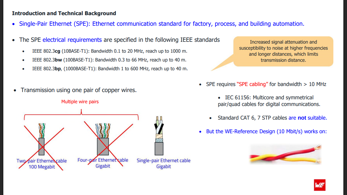
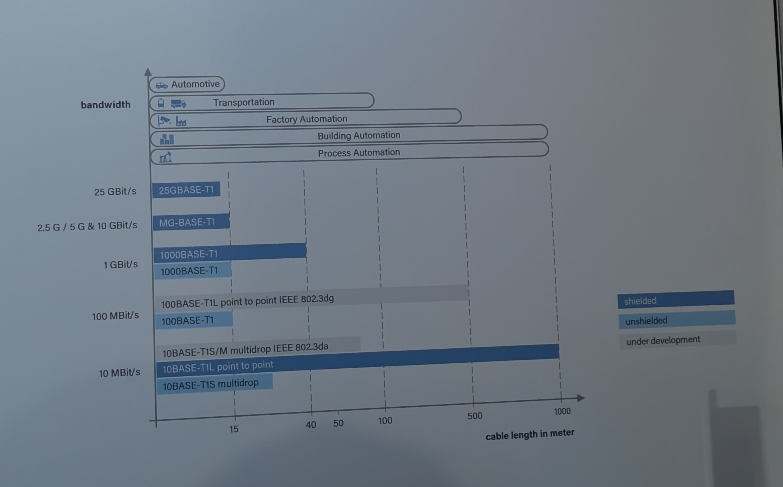
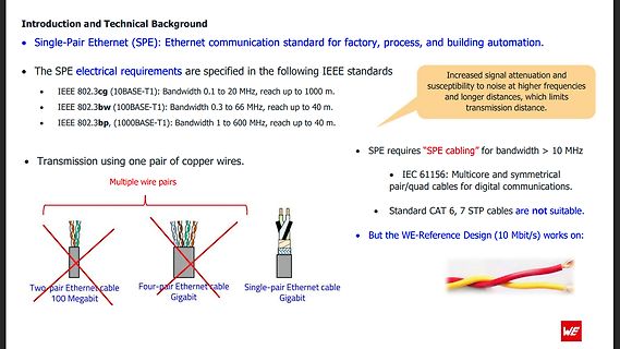
automation.
The SPE electrical requirements are specified in the following IEEE standards
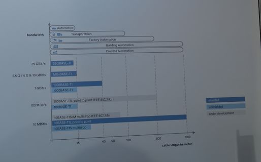
IEEE 802.3cg (10BASE-T1): Bandwidth 0.1 to 20 MHz, reach up to 1000 m.
IEEE 802.3bw (100BASE-T1): Bandwidth 0.3 to 66 MHz, reach up to 40 m.
IEEE 802.3bp (1000BASE-T1): Bandwidth 1 to 600 MHz, reach up to 40 m.
SPE requires
Speed Serial Peripheral Interface(SPI MODE 0, 3) - Internal 32Kbytes Memory for TX/RX Buffers - 10BaseT/100BaseTX Ethernet PHY embedded - Supports Auto Negotiation (Full and half duplex, 10 and 100-based ) - Not supports IP Fragmentation - 3.3V operation with 5V I/O signal tolerance - LED outputs (Full
Properties: Turns Ratio n 1 : 1 ±2% Plastic Housing Material Thermoplastic PA66 Black Data rate 100BASE-TX Plastic Housing Flammability Rating UL94 V-0 LED Electrical & Optical Properties: Shielding Material Brass Value Properties Test conditions min. max. Unit Shielding Plating 50µ" Nickel Forward Voltage
bis zu 12 t/s möglich sein könnten... und wenn es mir zu lahm ist, wird sie vielleicht durch zwei P40 oder P100 ersetzt, aber dann... genau, das Netzteil. :-)
Wenn die Betriebsspannung 40 V beträgt, ist die Ruhespannung zwischen den Endstufentransistoren ca. 20 V. Dann ist der Strom durch R3 und R4: I = (Ub / 2) / (R3 + R4) = (40 V / 2) / (220 Ω + 82 Ω) = 20 V / 302 Ω = 66 mA.
Wie sieht es denn mit den Kondensatorspannungen auf der auch mit 40V versorgten Rhythmusplatine aus? Irgendein Indiz, dass 40V zu hoch sein könnten?
wireless connection ensures that the mobile unit consistently receives the necessary RTCM data from the base station, maintaining high-precision positioning even at a distance. [/c] ### Microchip PIC32CM * PL10 – mit AVR Dx kompatibler 32-Bitter Microchip möchte Nutzern der AVR Dx-Familie einen Weg zum
auf Lochraster. > Wer's mag. https://www.reichelt.de/de/de/shop/produkt/ic-pinrichtgeraet_bis_40-polige_dil-ic_s-15399
the vicinity of the test stand or you can fit swivel arm 1 688 006 133 (special accessory) instead. 40 12.3 Overview – 1,44 MB – Floppy disk drive 1 687 022 272 (Teac FD-235 HF-3201-U) Plug-in jumper X6 of CPU pc board at position H 1 687 022 299 (Teac FD-235 HF-5429-U5) ! Plug-in jumper X6 of CPU pc
Und irgendwelche Verbote oder Pfand-Systeme laufen in's Leere. Erlaubt sind 2ml Tankinhalt mit 40mg Nikotin (20mg/ml), wie die "Elfbar" aus dem Eröffnungsbeitrag. Da gehen ca. ¼ vom Verkaufspreis an den Staat (MwSt + Tabaksteuer) Beim Späti deines Vertrauens kriegst du zum fast selben Preis Schmuggel-Vapes
mit Blick auf Risikominimierung kontrolliert würde, dann dürfte das Nikotin da auch nicht als freie Base drin sein – es gibt keinen anderen Grund für diesen Aufwand, als das Suchtpotenzial zu erhöhen. In der Ursprungsform ist das Nikotin in Liquids kaum suchterzeugend und vermag daher, den völligen Ausstieg
SOIC (8) 4.90 mm × 3.91 • Gaming and Computer Accessories mm BQ2057, BQ2057C, TSSOP (8) 3.00 mm × 4.40 • Portable Medical Equipment BQ2057T,BQ2057W mm • EPOS Card Reader BQ2057, BQ2057C MSOP (8) (2) 3.00 mm × 3.00 3 Description mm The BQ2057 series advanced lithium-ion (Li-ion) and (1) For all available
bei Reichelt (ca. 1,00 ) PCA 82C251. von NXP (ex. Philips) PDIP8 und SO8 VCC = 4,5...5,5V V-CAN: -40V..+40V -> +24V Bus-Spannung erhältlich z. B. bei Reichelt (ca. 1,50 ) TJA 1041. von NXP (ex. Philips) SO14 VCC = 4,75...5,25V Standby, Sleepmode 1 MBit/s -27..+40V Automatische Einstellung der I/O Pegel
Schutz abgekündigt: ähnliche Funktionen, gleicher Hersteller: TJA1053, TJA1054 UJA1061. NXP System Base Chip (SBC) TSSOP 32-Pin Serial Interface (SPI) Spannungsregler 3.3 V oder 5.0 V (LDO) 6kV ESD Schutz L4969. ST Microelectronics System Base Chip (SBC) SO20 Serial Interface (SPI) Spannungsregler (LDO
Arduino .. vom Atmega8 zur 40TOPs NPU: https://www.arduino.cc/product-ventuno-q .. was für ein Werdegang.
Anwendung für so ein Board vorstellen. Egal > welches, muss ja nicht Arduino sein. Das Board zielt mit 40TOPs ganz klar auf KI-Anwendungen. Ich meine, dass das ungefähr die Leistungsanforderung von Microsoft für die KI-PCs ist. Außerdem hat es ja nebenbei noch den HexaCore und die 16GB Ram. Anwendungen

 Bild
Bild
 Bild
Bild
 Bild
Bild
 Bild
Bild