register 0x11CF R16_AUX_POWER_ADJ 0x40001022 Auxiliary power adjustment control register0x0XXX R8_BAT_DET_CTRL 0x40001024 Battery voltage detection control register 0x00 R8_BAT_DET_CFG 0x40001025 Battery voltage detection configuration regis0x02 R8_BAT_STATUS 0x40001026 Battery status register 0x00
hard drive ...................................................................................... 42 Installing a 2.5-inch hard drive ....................................................................................... 43 Removing and installing an M.2 SSD storage card ...........................
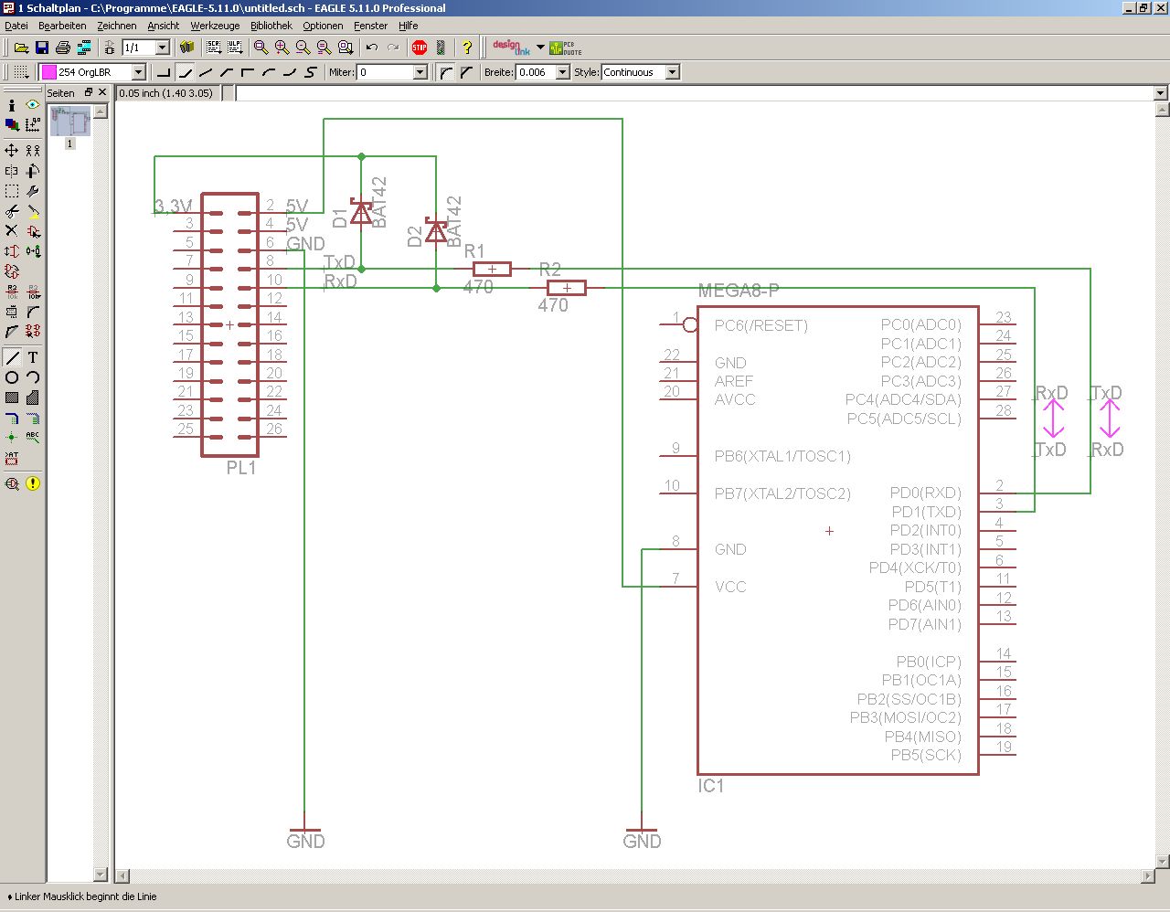
Schottkydiode hat typisch den 20..100 -fachen Sperrstrom einer "normalen" Si-Diode. Z.B. 1N4148 max. 25nA, BAT42 max. 500nA (jeweils @25V, @25°C). Stark ansteigend mit der Temperatur, auf 3µA resp. 100µA bei 100°C. Lies mal Datenblätter! Abgesehen davon *hat* der ADC-Eingang des µC aber schon Klemmdioden
Schottkydiode hat typisch den 20..100 -fachen Sperrstrom einer > "normalen" Si-Diode. Z.B. 1N4148 max. 25nA, BAT42 max. 500nA (jeweils > @25V, @25°C). Stark ansteigend mit der Temperatur, auf 3µA resp. 100µA > bei 100°C. Lies mal Datenblätter! Nochmal Blödsinn. Der Sperrstrom von Schottkys hat mir bei ein
er service centres structions for only. charging and never charge the Special safety battery or the bat- directions for bat- tery-powered tool tery-operated tools outside the temper- ature range stated • Ensure that the in the operating in- device is switched 41 GB MT off before inserting • Allow a hot
GND MTDI/IO41/PDM_DATA/RX1 18 B1/A12/GND GND 1 1 1 1 1 2 2 2 2 2 2 2 2 2 GPIO41_PDM_DATA/RX1 MTMS/IO42/PDM_CLK/TX1 19 GPIO42_PDM_CLK/TX1 GND 1 IO10/XMCLK/ADC_BAT 20 S3 I 1 K GPIO10_XMCLK/ADC_BAT GND U5 T S S S S4 PY25Q128HA-DFH-IR B M MI I E C I I / Y Y Y Y D D _ GND SPICS0 1 CS# VCC 8 VDD_SPI D S S L
...................................................................................................42 1.9 Denomination - Key to DC-Compressor type designation...................................................................................42 1.10 Date code & country of origin.......................
environment variable” and “Add registry information”, and disable “Show Readme” and “Launch gccvar.bat”. A Windows package for OpenOCD can be obtained from the gnu-mcu-eclipse downloads page. Download the appropriate file, e.g. " gnu-mcu-eclipse-openocd-0.10.0-12-20190422-2015-win64.zip”. The archive
encoded in the instruction, but it can be done like this: The resulting instruction will contain “42” as the jump offset. As suggested by the syntax, the processor multiples this number by 2 (since instructions can only reside at even memory addresses, it would waste one bit of memory to specify the
) - 4000 V VESD – STATUS ( s 4000 V – OUTPUT c t 5000 V – VCCd u 5000 V EMAX (L = 0.14 mH;LR 0 Ω; bat 13.5 V;jstart150 °C; 52 mJ e P L= 14 A) e t Ptot Power dissipation (per islanlead 25 °C 74 W o l T j Junction operating temperature Internally limite°C b s Tc Case operating temperature - 40 to 150
ratings (continued) Symbol Parameter Value Unit Maximum switching energy EMAX (L = 0.25 mH; L = 0 Ω; bat= 13.5 V; 362 mJ T = 150 °C; I = 45 A) jstart L P Power dissipation T ≤ 25 °C 96.1 W tot C T Junction operating temperature Internally limited °C j Tc Case operating temperature -40 to 150 °C TSTG Storage
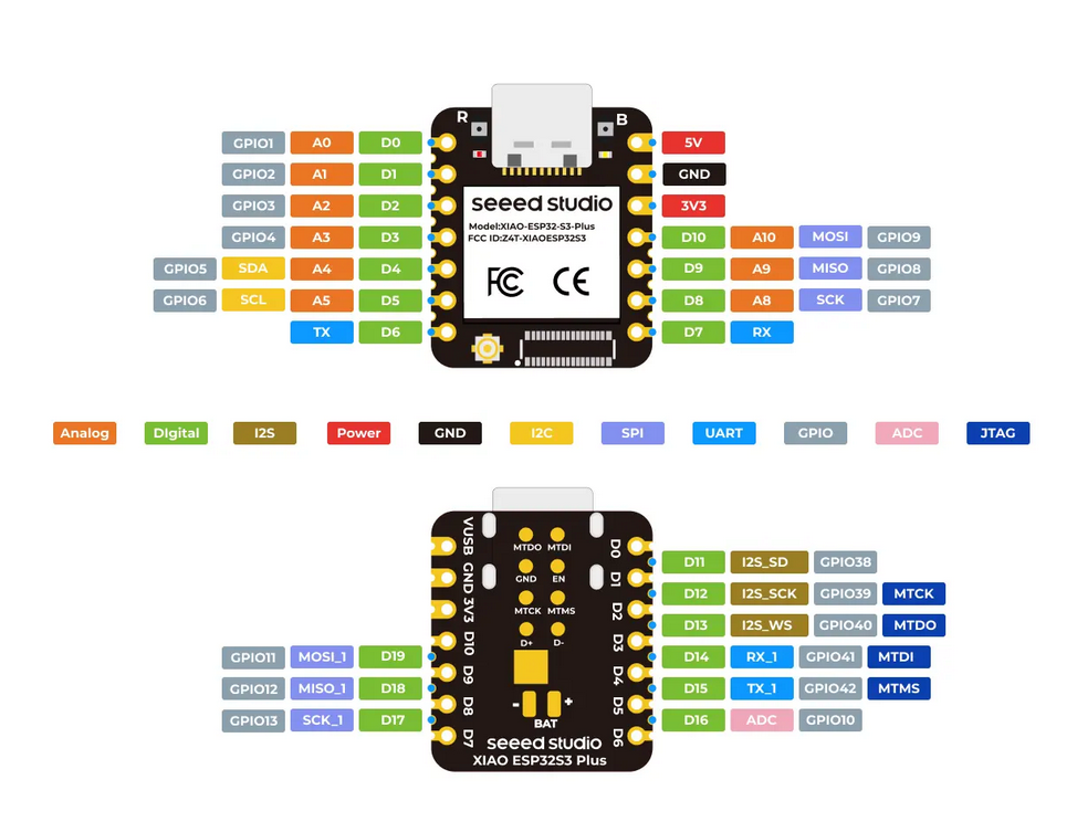
Kunstoffkörper, 2x1 Stiftleiste, bei Bedarf noch Buchsenleisten für den ESP32-S3-Nano.Alles 2,54mm Raster. * BAT42 Schottky-Dioden * Bei zwei der ESP32 sind die PIN-Leisten noch nicht gelötet ESPhome lässt sich auch für das Versenden von MQTT-Nachrichten konfigurieren und kann dann mit allen Systemen arbeiten
VBAT > VPF VPF Switchover Voltage V SW V VBAT < VPF VBAT > VCC V = 3V 250 Battery Current, SQW Off I BAT nA (Note 5) BAT1 VBAT = VBATMAX 600 Battery Current, SQW On VBAT = 3V 550 (Note 6) BAT2 nA VBAT = VBATMAX 1100 Data-Retention Current (Note 7) I V = 3V 25 100 nA BATDAT BAT AC Electrical Characteristics
Dergute W. schrieb im Beitrag #7813631: > Damit haben send_bat_wrapper() und read_bat_voltage_avg() die selbe > Geschmacksrichtung von Funktionspointer: > float send_bat_wrapper(void) { > float rc; > rc = (float)send_bat(); > return rc; > } >
, OA 47, OA625, GA100, Alternativ die gut erhältlichen modernen Silizium Schottky-Dioden wie z.B.: BAT43, BAT48, HP5082-2835, HSMS -2820 (SMD), SD103C, 1SS16 Germanium Spitzendioden werden nur noch vereinzelt hergestellt. Sie haben eine niedrige Schwellenspannung unterliegen aber auch großen Fertigungstoleranzen
2 + GND 3 GND N 11 ILIM SYS 14 10uf 100nf C VS GND G 12 TS BAT 13 1 - C C11 IR26-51C/L110/TR8 E QON# BAT BAT 100nf R4 R GND GND checked VOUT 0 IR1 IR2 1 N CHANNEL MOSFET 0603 SIZE CAPACITOR AND RESISTOR U4 KEY1 GND A03400 R23 Switch,3*6*5Plastic R11 GND 10k 150R
2 + GND 3 GND N 11 ILIM SYS 14 10uf 100nf C VS GND G 12 TS BAT 13 1 - C C11 IR26-51C/L110/TR8 E QON# BAT BAT 100nf R4 R GND GND checked VOUT 0 IR1 IR2 1 N CHANNEL MOSFET 0603 SIZE CAPACITOR AND RESISTOR U4 KEY1 GND A03400 R23 Switch,3*6*5Plastic R11 GND 10k 150R
R DSon drain-source switch-on resistance of a power MOSFET t generally time U generally voltage U Bat+ positive voltage of the whole battery U Bat− negative voltage of the whole battery U Cell voltage of the selected accumulator cell (equal to U2) U GS gate-source voltage of a MOSFET U Out output (input
an die Spule des Moduls angeschlossen Lilon 3,7V in SW-L 470 MOSFET im IC f-SW ca. 0,3MHz 1R2 470nF BAT42 BAT42 100uF 100nF -5,2V out 1N4148 (!) 100uF 100nF +5,0V out GND GND SW-IC: E5 OD wahrscheinlich BL8530 von Shanghai Belling
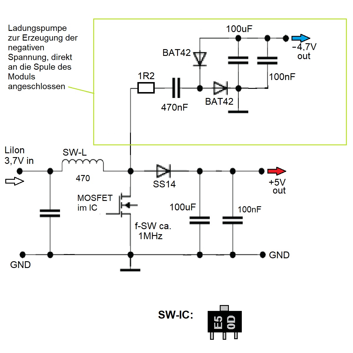
Ladungspumpe zur Erzeugung der negativen Spannung, direkt an die Spule des Moduls angeschlossen 100uF BAT42 -4,7V out BAT42 100nF 1R2 470nF Lilon 3,7V in SW-L 470 SS14 +5V out MOSFET im IC 100uF 100nF f-SW ca. 1MHz GND GND SW-IC: E5 OD
die Ladetechnik bzw. an das Batteriemanagementsystem. Die Folge dieser Entwicklung sind frühzeitige Bat- terieausfälle, welche bei neuen Fahrzeugen bereits nach 1-2 Jahren [ADAC06], bei Oberklassemodellen bereits nach einigen Monaten [Sp04],[Ra04] auftreten können. Es stellt sich daher die Frage, in wie
Nach der Bestätigung mit „OK/Menu“ wird die aus demAkku entnommene Kapazität angezeigt (Abbildung 42). Bild 38: Zeiteinstellung für Displayhin- Bild 40: Auswahl der Anzeigefunk- terleuchtung tion im automatischen Wechsel Bild 39: Einstellung des Displaykon- Bild 41: Softwaremäßiger Abgleich Bild 42:
Moin, Der Typ wird wohl eher ziemlich unkritisch sein. Vielleicht ne BAT54 oder sowas. Was halt grad so rumfliegt. Vielleicht gehts auch schon mit ner 1N4148 oder sowas. Gruss WK
Für den Zweck geht jede Kleinsignal Schottkydiode. Zum Beispiel eine BAT42, BAT48, 1N5817, 1N5818 usw. Hans Markus G. schrieb im Beitrag #7737755: > jetzt muss ich nur noch verstehen wie das vervielfachen funktioniert ;-) Hier gut erklärt: https://www.elektroniktutor.de
0,1uF C47 R15 C SG3525A D4 10uF 220E F u + C17 1 D5 L2 470uF/16V C40 C C AGND D6 0,1uF 100uH/1A +5V BAT54S -12V A K (ch nummern mit linearer DSP adressierung) C30 4n7 M D7 CH3 R19 (ch3) 3k3 BAT54S A K C31 4n7 M D8 CH4 R20 (ch4) +12V 3k3 BAT54S A K C32 4n7 M D9 CH7 (ch7) R21 39k 3k3 R16 J4-1 BAT54S A K C33 4n7 U13 0E15 +5V J4-9 M CH8 (ch8) 1 8 R18 R22 D10 2 -IN VIN 7 3k3 C19 +IN CL J4-2 BAT54S 3 OSC C 6 B A K 4 GND E 5 L1 B C34 4n7 M 22p J4-10 D11 CH1 (ch1) LM3578 R23 ??? 3k3 D 220uH/300mA + C20 J4-3 BAT54S k 7 C18 A K 1 R C35 4n7 M 470uF J4-11 D12 CH2 (ch2) 1n2 R24 3k3 J4-4 BAT54S A K
Wegen des Markings bin ich nicht sicher, aber es könnten AT42QT1011 sein. Auf alle Fälle sieht das Oszi-Bild komisch aus. Sieht aus wie 50 Hz Brumm an offenen Eingängen. Oder sieht die Betriebsspannung auch so aus?
...................................................................................................42 1.9 Denomination - Key to DC-Compressor type designation...................................................................................42 1.10 Date code & country of origin.......................
updated after the falling edge of the clock input. 3.7 Multifunction Pin (MFP) 3.2 Backup Supply (V BAT ) The MFP pin is shared with the clock divider and the This is the input for a backup supply to maintain the alarms. This pin requires an external pull-upCCoor RTCC and SRAM registers during the time
Andrew T. schrieb im Beitrag #7690176: > In guter Näherung reicht vollauf. Das sind dann 42A bei 42°C
Ich habe mal alles abgeklemmt und "Durchgang" gemessen... Also durch den WR ist PV Masse mit BAT Masse durchgänging. Also Multimeter piepst und zeigt 0... Ich habe dann auch mal die Verbindung überlegt und "nachgezeichnet"... Der ADS musst ja die Differenz. (Pinke Linie) Die Masseverbindung

 Bild
Bild
 Bild
Bild
 Bild
Bild
 Bild
Bild
 Bild
Bild

 Bild
Bild