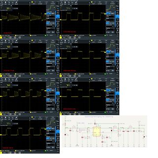
86V haben. Damit darf die Zenerdiode in Reihe zu D1 z.B. 1x 68V haben, was das Abschalten (das 40.51.9 kann 3ms) noch schneller macht wie bei kleineren Löschspannungen. R4 weglassen.
Was, wenn Du einfach die PTT 100ms verzögerst? Dann hast Du alle Zeit der Welt.
Deditor enables you to create and edit MEGATEXT and MEGATEXT PLUS display pages and can be installed in MS-Windows 3.xx and Windows 95. It supports all the display modes in the MEGATEXT and MEGATEXT PLUS hardware: character display, graphics, DRCS characters, color lookup table, and row and screen attributes
Industrial Wireless Technology • AP-agnostic seamless roaming with client-based Turbo Roaming for sub-150 ms roaming recovery times between APs (in Client mode) • 2x2 MIMO technology for improved multi-stream data transmission and reception • DFS channel support for a wider range of 5 GHz channels to avoid
signal travel time (Figure 6). Satellite and Satellite and receiver clock receiver clock display: 0ms display: 67.3ms 0ms 0ms 75ms 25ms 75ms 25ms 50ms 50ms Signal Signal transmission (start time) Signal reception (stop time) Figure 6: Determining the signal travel time As with the example of the car,
28 99 R506 T 111 83 R810 T 45 37 IC802 T 56 43 C403 T 68 24 C733 T 155 38 C870 T 48 50 C1104 T 179 51 IC900 T 77 75 L1408 T 18 99 R507 T 149 77 R811 T 182 15 C404 T 17 21 C734 T 155 40 C875 T 72 44 C1105 T 112 24 IC901 T 78 52 L1409 T 43 110 R508 T 154 103 R812 T 51 68 C405 T 69 19 C735 T 161 23 C876
modulation; a pulse width of 1.5 ms corresponds to going pulse, the duration of which is the neutral or ‘straight ahead’ position, equal to the difference between 3 ms whilst 1 and 2 ms represent the extreme and the original control pulse
Standby state.) The reset signal is delayed and reconstructed in U10(TF301SC10). The reset output of U10.51 is provided to all the system. - Check point 1 - In normal state, the ‘nRESETIN’ signal is 3.3V. If it is about 0V, U11 has problem. - Check point 2 - U10.50 and U10.51 should be 3.3V. If only U10.50
MS3x ;Kein Überlauf ldi AH, 0 sts PWM5, AH sts PWM3, AL ;Übertrag com AL sts PWM4, AL ldi AL, LOW(MS4) sts PWMAdrl, AL ldi AL, HIGH(MS4) sts PWMAdrh, AL ret MS32: ;rechts rum sbc AL, AH brcc MS3x ;Kein
⋅C 0.003% Minimum output current to VI– VO = 125 V 15 mA maintain regulation VI– VO = 25 V, t = 1 ms 1100 V – V = 15 V, t = 30 ms 715 Peak output current I O mA VI– VO = 25 V, t = 30 ms 700 900 VI– VO = 125 V, t = 30 ms 100 250 ADJ input current 83 110 A Change in V – V = 15 V to 125 V, I = 15 mA to
Gernot schrieb im Beitrag #8050408: > MS51FB9AE Um den (neu) zu programmieren braucht man (neben der Versorgung) die Pins ICE_DAT, ICE_CLK und nReset (Seite 33): https://www.nuvoton.com/export/resource-files/DS_MS51FB9AE_MS51XB9AE_MS51XB9BE_EN_Rev1
line regulation effects. Specifications are for a 200 mAload pINse at V 20V (a 4W pulse) for T = 10 ms. 10: Comparator thresholds are expressed in terms of a voltage differential at the adjust terminal below the nominal reference voltage measured at 6V input. To express these thresholds in terms of output
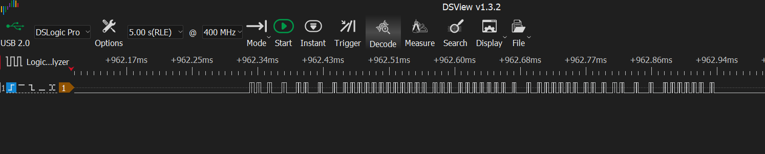
und Seite 9: > Die Output-Delay-Time ist 50ms bis 100ms, > die Logisch 0 Pulse sind 40ms bis 130ms lang, > die Logisch 1 Pulse 140ms bis bis 230ms lang. Ja, 2023 hatte ich an einem Pollin-Modul die Impulszeiten gemessen, siehe dort: https
wp-content/uploads/2016/05/da6181B.pdf >> Siehe Seite 3 und Seite 9: >> Die Output-Delay-Time ist 50ms bis 100ms, >> die Logisch 0 Pulse sind 40ms bis 130ms lang, >> die Logisch 1 Pulse 140ms bis bis 230ms lang. Typischer Fall von falscher Interpretation. Ja, die Impulsdauern schwanken abhängig vom
R R NO MSIR * UL T5 E L O H MRTT CME 1 A EHR :I R YDCM IR -. : UHUTT 2U NI AREY A- IUG : OTOIO 2S MS **RA MP R 1 W OLUSE S C D U E M S C D D C T D Figure O-4. Schéma du four - Condition de marche R-733 - 27 DIAGRAMME SCHEMATIQUE . . N U H I E U A A E R I S . E N ET . I E E VDE R A O I U U HER U D D
DS005671-50 DS005671-49 t 20 ns r Timing Diagrams (All timing is measured frovoltage points) DS005671-51 www.national.com 6 A D Timing Diagrams (All timing is measured frovoltage points) (Continued) C 8 1 Output Enable and Reset with INTR A D C 8 0 A D C 8 0 / D C 0 0 / A C 0 0 DS005671-52 5 Note: Read
= 0; dcf77_tick (); } } net_time_cnt++; if (net_time_cnt == F_INTERRUPTS / 100) // set esp8266_ten_ms_tick every 1/100 of a second { esp8266_ten_ms_tick = 1; net_time_cnt = 0; } #ifndef BLACK_BOARD // eeprom not used on STM32F407VE eeprom_cnt++; if (eeprom_cnt == F_INTERRUPTS / 1000) // set eep_ms_tick every 1/1000 of a second { eeprom_ms_tick = 1; eeprom_cnt = 0; } #endif if (ambilight_clock_wait_cycles) // wait cycles for ambilight mode clock & clock2 { ambilight_clock_wait_cnt++; if (ambilight_clock_wait_cnt >= ambilight_clock_wait_cycles
Offenbar ist in manchen/allen MS309 Clones ein STC 8051er sowie ein Microchip CAN-Controller MCP2515: https://mysku.club/blog/china-stores/42583.html In dem Fall, wie auf der russischen Seite gezeigt, ein STC89LE51RD-40C: 61 kB
Is there anything I can help you with today? total duration: 12.755300431s load duration: 323.007954ms prompt eval count: 12 token(s) prompt eval duration: 72.503984ms prompt eval rate: 165.51 tokens/s eval count: 272 token(s) eval duration: 12.087102373s eval rate: 22.50 tokens/s
32256 bytes) Building .pio\build\uno\firmware.hex Ohne DMA und mit den Berechnungen wird der AVR >1ms für den Refresh brauchen, vielleicht 2ms.
Rudolph R. schrieb im Beitrag #8045811: > Ohne DMA und mit den Berechnungen wird der AVR >1ms für den Refresh > brauchen, vielleicht 2ms. Da ich das in den Raum geworfen habe muss ich auch berichten, dass ich mit meiner Einschätzung ganz weit daneben lag. Ich habe das gerade auf einem Arduino
VCC=5.0 V 6.5 8 mA Time from VCC > 4.5V to valid Vout and Vref Power Up Time TVCC (Note 2) 0.75 1.25 ms Primary Side Input Measure resistance between IP+ and IP- Primary Conductor MCA1101-50 Versions (Note 2) 0.9 Resistance RPC Measure resistance between IP+ and IP- mΩ 1.3 MCA1101-20, MCA1101-5CONFIDENTIALote
diesen Müll hier abzulassen? Benutzername kawaii Vorname Roger Angemeldet seit 15.04.2026 00:51 Beiträge 7
Rolf schrieb im Beitrag #8040083: > In MS Word kann man das von der Autokorrektur erledigen lassen. Die > setzt die Sequenz $% (Beispiel!) in ein geschütztes Leerzeichen um, und > zwar ohne weiteres Zutun unmittelbar beim Tippen. In Word
/O port with internal pullups. It also serves the functions of various special features of the MCS-51 Family, as listed below: P o rP i n A l t e r F u n c t i o n P3.0 RXD (serial input port) P3.1 TXD (serial output port) P3.2 INTO (external interrupt) P3.3 INT1 (external interrupt) P3.4 TO (Timer/counter
eee eee 68D Fig.50. Waveform, ADC part... 0.0... c c e e e n e ee eee eee ee eee e e e ) BI 08 Fig.51. Waveforms, digital part 2... 0... c e e e e e e e eee tee et e e n s B82 . Fig.52. Waveforms, free-run .. 0 . . . e t e e e e e e e ee ee BE : Fig.53. Switch for high current ranges... 0 . 6 ee e e
hxwxd} +95x236x280 Weight kg Cabinet material 2A B S 1.25. S A F E T Y Clas +11,for the other versions/51version, 2 4 2. C I R C U I T D E S C R I P T I O N ‘as shown in Fig. 2.1. — PM 2519/21 In thebatteryversion (PM 2519/21} arechargeablebattery isused to supply the — PM 2519/51 ‘The PM 2519/51 version
s ) 2 Maximum shock (m/s ) 2 Side-on type 13 mm (1/2 inch) diameter 100 (10 Hz to 2000 Hz) 1000 (6 ms) 28 mm (1-1/8 inch) diameter 100 (10 Hz to 500 Hz) 1000 (11 ms) Metal package TO-8 100 (10 Hz to 500 Hz) 1000 (11 ms) 13 mm (1/2 inch) diameter 100 (10 Hz to 500 Hz) 1000 (11 ms) Head-on type 28 mm (1-1/8 inch) diameter 50 (10 Hz to 500 Hz) 1000 (11 ms) 51 mm (2 inch) diameter 50 (10 Hz to 500 Hz) 750 (11 ms) 76 mm (3 inch) diameter 50 (10 Hz to 500 Hz) 750 (11 ms) The photomultiplier tube envelope is made of glass, so it is vulnerable to direct mechanical
mV 50 Ω 500 MS/s 50 mV DC x 100 3 1 DC -5.4 mV j STOPPED 4 .1 V DC x 10 Figure 28. V Losses CE(sat) Measuring the dynamic V CE(sat) under high VCE value, is recover from the +400 V coming from the rail voltage, not
www.onsemi.com 6-Pin DIP Zero-Cross Triac Driver Optocoupler (800 V Peak) MOC3081M, MOC3082M, PDIP6 8.51x6.35, 2.54PPDIP6 8.51x6.35, 2.54P CASE 646BY CASE 646BZ MOC3083M Description The MOC3081M, MOC3082M and MOC3083M devices consist of a GaAs infrared emitting diode optically coupled to a monolithic silicon
Unternehmertum. 2025: Umsatz 113 Mrd, Operatives Ergebnis 29,3 Mrd, Nettogewinn 8,4 Mrd, Nettoschulden 51,5 Mrd (rund 3 Mrd. weniger als 24). Der Kapitaldienst wird erbracht. Der Laden ist gesund.
The Monitor and Download Interface (MSDA/MSCL) supports E-ROM download and ERASE/WRITE as fast as 700ms for 4 kByte. 2. Factory programmed versions with custom EROM content are available. The actual customer application code and customer EEPROM fabkey is specified by a 2 digit code at location marked “
> 9-Bit-Wörter einstellen lässt. Das stimmt nicht. Sowas war bei unseren Opas mal gaengig in MCS51. War wohl mal so eine Siemensidee fuer Bussysteme. The MCS-51 (8051) microcontroller family supports 9-bit serial communication in Modes 2 and 3, primarily designed for multiprocessor master-slave
jedem Datenpaket ist eine längere High-Phase. Also stell den Trigger des Oszis auf "High länger als 5ms", dann bekommst du den Anfang eines Datenpaketsubd kannst dann die Bits auszählen. Und das, was du hast sind keine RS232-Pegel, sondern offenbar TTL-Pegel.
außerdem einige Analogausgänge. Die PCIe-Variante hat keine Ausgänge, sampelt dafür aber mit bis zu 10MS. ### Advantech PCIE-1682F – PCIe-zu-CAN-FD-Konverter Im Hause Advantech ist man PCIe-Karten auch sonst nicht abgeneigt – Variante 1682F stellt zwei CAN FD-Ports zur Verfügung. ### Abracon AB-RTC-XP
range of 0.9V to 5.5V with low power consumption (190nA @ 3V) [/c] ### Carlo Gavazzi DPA01 / DPA51 / DPA52 – explosionssichere Relais für umweltfreundliche Klimaanlagen (!!!) Die Verwendung von ozonlochfreundlicheren Kältemitteln geht mit einer Erhöhung der Explosionsgefahr einher. Carlo Gavazzi
ich weiterhin Normal = 10,780V und Sleep = 10,112V. Mach nach der Warte Zeit, in was eigentlich ms? ggf mal nachmessen, auch den EN mit aus. Beim Original von NXP war das zwar theoretisch so das er da sein IHN in High Impedance setzten sollte aber das glaube ich erst wenn dann auch die VCC5 und so
0,33 mA. Damit bin ich extrem sicher unter dem 1 mA Limit aus dem Datenblatt! 2. Basisstrom: Der 51kΩ Pull-down-Widerstand zieht bei den 0,7V Basisspannung nur winzige 0,014 mA ab. Es bleiben also knapp 0,31 mA effektiver Basisstrom für den Transistor übrig. 3. Kollektorstrom & Mosfet-Gate: Wenn

 Bild
 Bild
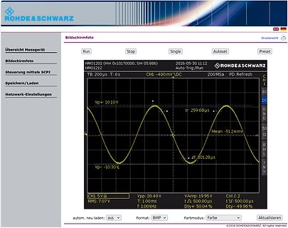
 Bild
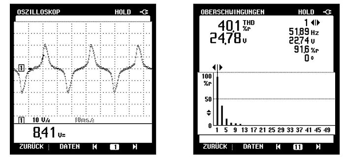
 Bild
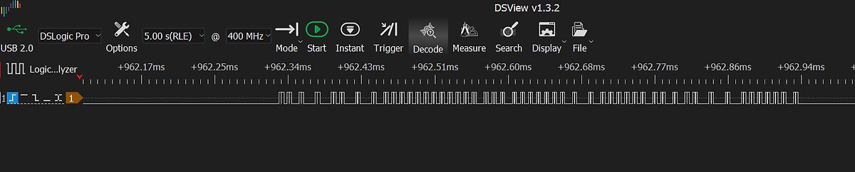
 Bild
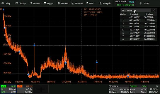
 Bild