-
PDF
slaa323a.pdf
associated with this application report and contains the entire data set. 2.6 2.5 2.4 2.3 2.2 2.1 2 Ideal 12 bits 1.9 1.8 1.7 Ideal 16−bit t 1.6 bits p I 1.5 g 1.4 t Oversampled o 1.3 results V o 1.2 a 1.1 A 1 0.9 0.8 0.7 0.6 0.5 0.4 0.3 0.2 0.1 0 0 0 0 5 0 5 0 5 0 5 0 5 0 5 0 0 0 0 0 0 0 0 0 0 0 0 0 Sample
-
PDF
ET0570A1DH6.pdf
Randfläche und slim frame and only 6 mm TFT thickness lediglich 6 mm Stärke plus Platine. plus PCB. Es ist ideal für jegliche Applikationen die Ideal for any application with minimum wenig Platz bieten (mobile & portable available space (mobile & portable devices). Geräte). Keine überflüssigen Befestigungsränder
in „Problem QVGA-TFT an S1D13705“ · Mikrocontroller und Digitale Elektronik ·
-
PDF
Messung_der_Kapazitaet_unter_Last.pdf
der Ladestrom sofort und wird entsprechend der Zeitfunktion der Ladespannung abgebaut. Für einen idealen Kondensator entspricht die Zeit der Dauer Aufladung von Prozent der Spannungsdifferenz eines Spannungssprungs ΔV. Der Strom erreicht nach exakt Prozent seiner maximalen Auslenkung. V V i V l t 1/e
in „Kapazität bei angelegter Hochspannung“ · Analoge Elektronik und Schaltungstechnik ·
-
PDF
deembedding_1_.pdf
pylab import * rf.stylely() from skrf.calibration import SOLT # a list of Network types, holding 'ideal' responses my_ideals = [ rf.Network('load.s2p'), rf.Network('open.s2p'), rf.Network('short.s2p'), rf.Network('thru.s2p'), ] # a list of Network types, holding 'measured' responses my_measured = [ rf.Network
-
PDF
LTSpice_XVII__Tutorial.pdf
. Einpuls-Gleichrichter ohne Trafo 58 8.2. Einpuls-Gleichrichter mit Transformator 59 8.2.1. Ein idealer Trafo muss her! 59 8.2.2. Einpuls-Gleichrichter mit idealem Trafo 60 8.2.3. Erstellung des SPICE-Modells für einen realistischen Transformator mit zwei Wicklungen 61 8.2.4. Erzeugung eines passenden
in „Triac selbsterhaltend triggern“ · Analoge Elektronik und Schaltungstechnik ·
-
PDF
LTSpice_XVII__Tutorial_korr.pdf
. Einpuls-Gleichrichter ohne Trafo 58 8.2. Einpuls-Gleichrichter mit Transformator 59 8.2.1. Ein idealer Trafo muss her! 59 8.2.2. Einpuls-Gleichrichter mit idealem Trafo 60 8.2.3. Erstellung des SPICE-Modells für einen realistischen Transformator mit zwei Wicklungen 61 8.2.4. Erzeugung eines passenden
in „Simulation LT Spice“ · Analoge Elektronik und Schaltungstechnik ·
-
PDF
Kapitel5.pdf
und der Veranschaulichung derselben ➢ Untersuchung von minimalphasigen Systemen, Allpass, und dem idealen Tiefpass ➢ Reale Filter ( Tiefpass, Hochpass, Bandpass, Bandsperre ) Kapitel 5: Seite 1 von 35 Signale und Systeme: Die Laplacetransformation 5.2 Einführung Die Fourier- bzw. Fourierrücktransformation
in „Analoger Filterentwurf“ · Analoge Elektronik und Schaltungstechnik ·
-
 Bild
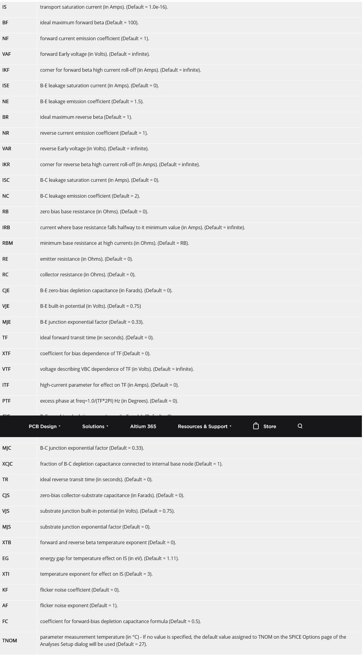
Liste von Transistor-Parametern in einer Software
IS transport saturation current in (Amps). (Default = 1.0e-16). BF ideal maximum forward beta (Default = 100). NF forward current emission coefficient (Default = 1). VAF forward Early voltage in (Volts). (Default = infinite). IKF corner for forward beta high current roll-off
in „keysight ads bjt transistor (Bipolartransistor) Parameter“ · Analoge Elektronik und Schaltungstechnik · · Screenshots

-
PDF
Testpunkte_M65p55.pdf
tape meets ANSA/EIA-481 standards • Simplifies testing on dense circuit boards MICRO MINIATURE • Ideal for use with miniature probes, clips and hooks • Ultra low profile, ideal for advanced surface mount PCB applications .040 [1.0] .040 [1.0] Pad Layout .060 [1.5] .135 [3.4] .070 [1.8] .105 [2.7] SPECIFICATIONS
in „Gehäuse von z.B. Jung für eigene Elektronik“ · Mikrocontroller und Digitale Elektronik ·
-
PDF
Filter.pdf
verschiedener Frequenzen Impulsformung Impedanzanpassung Filtertypen Tiefpass TP (Lowpass LP) Ein idealer Tiefpass weist folgende Dämpfungsfunktion auf 0 0 c A dB c A()/dB A()/dB Durchlassbereich Sperrbereich Ami (Passband) (Stopband) n A max 0 0 0 C 0 C H ideal real Reale Filter
in „Bessel Filter, Butterworth Filter“ · Analoge Elektronik und Schaltungstechnik ·
-
Datei
TCA785.txt
200 Rx3 72 74 100 Rin 53 54 1MEG Rf 1 65 100 1K Rf2 66 100 1K Rf3 67 100 1K Rf 4 68 100 1K Da 72 53 IDEAL Dc 55 100 IDEAL Dd 100 55 IDEAL Sa 51 100 52 100 SWITCH1 Sb 54 100 55 100 SWITCH2 VA 74 100 SIN (-0.5 0 0 0 0 0) Gi 100 51 VALUE={ (3.41/Ri) } Fr_. 52 100 TABLE {V (66) }= (-20,1) (-50E-6,1) (-20E-
in „TCA785.txt in Ltspice einfügen“ · Analoge Elektronik und Schaltungstechnik ·
-
PDF
class_f_and_inverse_class_f_W1.pdf
powers, dc power dissipations, and fundamental load impedances of both amplifiers are derived from the ideal current and voltage waveforms. Based on the formula, the performances are compared with a reasonable condition: fundamental output power levels of class-F and inverse class-F amplifiers are conditioned
in „Leistungsvertärker der F-Klasse“ · HF, Funk und Felder ·
-
PDF
Elpro_13.pdf
Capacitor, 220nF 1 C3 Capacitor, 4.7nF 3 C14, C13, C4 Capacitor, 33nF 1 C1 Connector 199 Crystal, ideal 1 Y1 Diode, D1N4007 5 D13, D12, D11, D14, D3 Diode, 1N4148 4 D16, D15, D10, D9 Ground 1 0 LED, green_LED 6 D7, D6, D5, D2, D4, D1 NPN Transistor, ideal 1 Q1 Node 58 Nonlinear Transformer, pq-4-24 1 T2 Nonlinear Transformer, PP3-12 1 T1 Nonlinear Transformer, ideal 1 T3 Polarized Capacitor, 470µF 1 C25 elpro_13.ewb Printed with the Student Edition of Electronics Workbench. Page 2 Polarized Capacitor, 47µF 2 C18, C17 Polarized Capacitor, 1µF 4 C8, C15, C6, C7
in „Torantrieb Steuerung IC Info gesucht“ · Analoge Elektronik und Schaltungstechnik ·
-
PDF
Elpro_13.pdf
Capacitor, 220nF 1 C3 Capacitor, 4.7nF 3 C14, C13, C4 Capacitor, 33nF 1 C1 Connector 199 Crystal, ideal 1 Y1 Diode, D1N4007 5 D13, D12, D11, D14, D3 Diode, 1N4148 4 D16, D15, D10, D9 Ground 1 0 LED, green_LED 6 D7, D6, D5, D2, D4, D1 NPN Transistor, ideal 1 Q1 Node 58 Nonlinear Transformer, pq-4-24 1 T2 Nonlinear Transformer, PP3-12 1 T1 Nonlinear Transformer, ideal 1 T3 elpro_13.ewb Printed with the Student Edition of Electronics Workbench. Page 2 Polarized Capacitor, 470µF 1 C25 Polarized Capacitor, 47µF 2 C18, C17 Polarized Capacitor, 1µF 4 C8, C15, C6, C7
in „Torantrieb Steuerung IC Info gesucht“ · Analoge Elektronik und Schaltungstechnik ·
-
PDF
Components_alphabetic_order.pdf
transmission NF 0 dB noise figure Noise Model: output noise according to noise figure NF System Simulation: ideal amplifier with noise figure according to ASE noise (EDFA) at 1550nm The parameters Z1 and Z2 are ignored. Digital Simulation: not supported Attenuator ideal attenuator Symbol: Default Name Value Description
-
PDF
CS8190-D.pdf
Output Angle in Polar Form Figure 5. Nominal Output Deviation 45 40 s e 35 g e 30 ( l 25 n l e 20 I 15 Ideal Degrees 10 Nominal Degrees 5 0 1 5 9 13 17 21 25 29 33 37 41 45 Nominal Angle (Degrees) Figure 6. Nominal Angle vs. Ideal Angle (After Calibrating at 180 ) http://onsemi.com 5 CS8190 Table 1. Function Generator Output Nominal Angle vs. Ideal Angle (After Calibrating at 270 ) Nominal Nominal Nominal Nominal Nominal Nominal Ideal q q Ideal q q Ideal q q Ideal q q Ideal q q Ideal q q Degrees Degrees Degrees Degrees Degrees Degrees Degrees
in „Drehspulinstrument (Air Core) steuern“ · Mikrocontroller und Digitale Elektronik ·
-
PDF
signalverarbeitung_ws-15-16_zweiter-termin.pdf
. c) Zeichnen Sie das Spektrum des ideal abgetasteten Signals u ¨ber drei Perioden f¨r den Fall, dass die gew¨hlte Abtastfrequenz nur 2/3 der nach dem Abtasttheorem notwendigen Abtast- frequenz betr¨gt. d) Aus den unter c) gewonnenen Abtastwerten
in „Nachhilfe in Signalverarbeitung - letzte Klausur des Studiums“ · Digitale Signalverarbeitung / DSP / Machine Learning ·
-
PDF
Modell.pdf
Gleichspannungsquelle beschrieben, die einen endli- chen Innenwiderstand besitzt. 3. Gleichstrommotor als idealer Wandler Zur Charakterisierung des Gleichstrommotors wurde die Kraft gemessen, die stationär auf einen Faden wirkt, wenn der Motor von einem Ankerstrom I Adurchflossen wird. Der Faden läuft dabei um
-
PDF
kopplungsfaktor_rel.pdf
den ub¨ichen Metho- den gemessen werden. Nun wird die zweite Spule kurzgeschlossen. Da von einer idealen Spule ohne Reihenverlustwiderstand ausgegangen wird, ist in diesem Fall auf der Sekunda¨seite R = 0. In diesem Fall vereinfacht sich Gleichung (5) zu ( 2) Z = j 1 − k !L 1 ′ 2 d.h. auf der Prim¨rseite
in „Kopplungsfaktor k messtechnisch ohne Kenntnis von L1, L2, Rs“ · Analoge Elektronik und Schaltungstechnik ·
-
PDF
Analysis_of_the_Sallen-Key_Architecture_sloa024b__TI.pdf
transfer function from gain block analysis gives: ȡ ȣ Vo+ ǒ ȧ 1 ȧ (5) Vi b 1 ) 1 * d Ȣ a f b bȤ 2.2 Ideal Transfer Function Assuming a(f)b is very large over the frequency of oper[ 0, the ideal a f b transfer function from gain block analysis becomes: Vo cȡ ȣ Vi+ ǒbȧ 1 d (6) Ȣ 1 * b By letting1 + K, c + N1 , and d +N2 , where N1, N2, and D are the b D D numerators and denominators shown above, the ideal equation can be rewritten as: Vo ȡ ȣ + ȧ K ȧ. Plugging in the generalized impedance terms gives the Vi Ȣ N1* KN12Ȥ ideal transfer function with impedance terms: Vo+ K Vi Z1Z2 Z1 Z2 Z1ǒ1*K Ǔ (7) Z3Z4
in „Bandpass und Phasenverschiebung“ · Mikrocontroller und Digitale Elektronik ·
-
PDF
Siemens_IntelligentDisplays1998.pdf
1 von 2 03.10.2016 19:13 Intelligent Displays file:///E:/PRODUCTS/37/3722.htm Addressable Display Ideal for User Defined Characters. Built-in Decoders, Multiplexers and LED Drivers. Readable from 6 Feet (1.8 SCDV 5540 / 183- meters). Wide Viewing Angle, X Axis ±55 deg, Y Axis ±55 deg. Attributes - 100
-
PDF
MCP41HVX1.pdf
is at Full-scale. V LSb(IDEAL)s the theoretical voltage step size. VIDEAL(@FS)is the ideal output voltage when the Wiper register code is at Full-scale. V is the theoretical voltage step size. LSb(IDEAL) VA VFS Actual Transfer
in „MCP41HVX READCMD falsch verstanden??“ · Mikrocontroller und Digitale Elektronik ·
-
PDF
CT220-Data-Sheet-Rev0.6.pdf
current sensor: Gain Error 𝑉𝑉𝑉𝑉𝑉𝑉𝑉𝑉𝑉𝑉𝑉𝑉𝑉𝑉 − 𝑏𝑏 𝐶𝐶𝐶𝐶𝐶𝐶𝐶𝐶𝐶𝐶𝐶𝐶𝐶𝐶 = The Ideal Transfer Line shows a line that reaches 95% of 𝑎𝑎 VDD at the maximum operating current and 5% of V DD at where a: slope and b: offset of the ideal curve. In a perfect the minimum. The datasheet also
in „Stromsensor CT220: Welche Stromstärken messen die verschiedenen Varianten?“ · Analoge Elektronik und Schaltungstechnik ·
-
 Bild
Produktseite EFR32BG24L Series 2 Bluetooth Wireless SoC
that offers up to 8x faster inferencing over Cortex-M, and consumes up to 6x lower power making it ideal for cost-effective intelligent edge nodes with a long battery life. The device prioritizes security with Secure Vault Mid, safeguarding against remote attacks. The pin-compatibility of this SoC with
in „Neue Zephyr-Kerne für Arduino, bionisch inspirierter Multikopter und Softwareupdates“ · Mikrocontroller und Digitale Elektronik · · Screenshots

-
PDF
ON_AND8230D_Application_Hints_for_Transient_Voltage_Suppression_Diode_Circuits.PDF
from the symmetrical clamping feature of a bidirectional TVS diode. http://onsemi.com 6 AND8230/D An ideal amplifier has an infinite Common Mode The remote sensor circuit also demonstrates a common Rejection Ratio (CMRR) and will only amplify the voltage solution for solving the non−ideal frequency response
in „uC Ausgeschaltet - Pin zieht auf GND“ · Mikrocontroller und Digitale Elektronik ·
-
PDF
INTERFACE_20.pdf
1,5mm x 1,5mm VL OR VCC 3 1 ac 1 OR 2 2 OR 1 3 OR 4 ANALOG DESIGN GUIDE 1 Multiplexer, Schalter • Ideal geeignet für • Kompatibel mit zukünftigen 2 Interface Mobiltelefone, Smart-Card- µPs und ASICs durch OpAmps, Komparatoren 2 ® 3 Anwendungen und I C - Betriebsspannung ab 1,2V DC-DC Wandler, Schnittstellen
in „galvanische Trennung RS232“ · Mikrocontroller und Digitale Elektronik ·
-
PDF
Sinewave_Dimmer_Technology.pdf
common: the phase control waveform is fully-on IGBT. Sinewave only has conducted losses, far from ideal for dimming them. In many cases the load will since the IGBTs are not operated in their linear re- perform poorly; in extreme cases the load (and possibly the gion. Sinewave has some losses through
in „Phasenan- bzw. abschnitt“ · Mikrocontroller und Digitale Elektronik ·
-
PDF
Sinewave_Dimmer_Technology.pdf
common: the phase control waveform is fully-on IGBT. Sinewave only has conducted losses, far from ideal for dimming them. In many cases the load will since the IGBTs are not operated in their linear re- perform poorly; in extreme cases the load (and possibly the gion. Sinewave has some losses through
in „Sinusdimmer“ · Mikrocontroller und Digitale Elektronik ·
-
PDF
Seiten_aus_Websterphysik.pdf
Randbedingungen zu ergan¨en ist. Der Einfachheit halber sei angenommen, daß das Horn bei x = x u1d x ent2 weder ideal offen oder ideal geschlossen sei. Gemaߨ(2.17) mus¨en dann α1,α2∈ {0,1} existieren,¨fur die P(x) in dem Definitionsbereich αj def 2 ∂ D AS = P(x) ∈ C ([x 1x 2,C) : P(x j = 0 f¨r j = 1,2 ∂x liegt, bzgl
-
PDF
sensors-09-04615.pdf
since—as shown in Figure 3—the lowest cosine error was obtained at this angle. Figure 3. Deviation from ideal cosine response for different angles in the machined in the TeflonTM diffuser. Deviation from ideal cosine response n i 1.20 n 1.00 Ideal f 0º s 0.80 n 0.60 25º p 35º r 0.40 45º a 0.20 u 55º A 0.00
in „Sonnenscheindauer Sensor selber bauen Eigenbau ATmega Assembler“ · Projekte & Code ·
-
PDF
AN1152_Achieving_Higher_ADC_Resolution.pdf
0.7326 mV/bit. This means the conversion of continuous voltages is quantization noise. The SNR Q of an ideal N-bit ADC is given by Equation 2. noise free if the continuous voltage is an integral multi- ple of the voltage resolution. Any intermediate continu- ous voltage is rounded off to suit a voltage level
in „Berechnung zur Auflösung ADC - wie richtig?“ · Mikrocontroller und Digitale Elektronik ·
-
PDF
Microsemi.LX2410A.pdf
LX2410A TM 10A IDEAL Bypass Device Description Features Package Thickness of 0.7mm (max) The LX2410A provides a bypass path for a string with voltage up to 33V. In the event of cell shading, Rated to a Forward Current
in „Was sind Idealdioden?“ · Analoge Elektronik und Schaltungstechnik ·
-
PDF
SSA_Cuk_Middlebrook.pdf
d ': l which changes when the duty ratio i s a func- tio n o f tim e, ( t.) I t i s through th is ideal transformer that the actual controlling function i s achieved when the feedback loop i s closed. In ideal addition the ideal transformer has a dc trans- formation r a tio d ' : l , while a real transformer
in „Verdammte Regelung eines 200W Buckwandlers!“ · Analoge Elektronik und Schaltungstechnik ·
-
PDF
ET057007DHU.pdf
Randfläche und slim frame and only 10.8 mm TFT thickness. das gesamte TFT lediglich 10.8 mm Stärke. Ideal for any application with minimum Es ist ideal für jegliche Applikationen die available space (mobile & portable devices). wenig Platz bieten (mobile & portable Geräte). Mounting lugs on each side make
in „Epson S1D13748 stellt sich tot“ · Mikrocontroller und Digitale Elektronik ·
-
PDF
start-booster-und-start-truck.pdf
Batterien Start Booster 1000 und 1600 · Portable, netzunabhängige Start-Geräte bzw. Energiestationen · Ideale Lösung für Starthilfe und Spannungserhaltung - egal wo · auch zum Betreiben aller 12 Volt Geräte über Zigarettenanzünder- stecker optimal geeignet. Ideal für Camping, Boote usw. · Keine Improvisation
in „Auto mit kleinem Bleigelakku starten/anlassen?“ · Offtopic ·
-
PDF
signalverarbeitung_ws-15-16_erster-termin.pdf
die nach dem Abtasttheorem zula ¨ssige minimale Abtastfrequenz an. b) Zeichnen Sie das Spektrum des ideal abgetasteten Signals ▯ x dt) = x(t)δ Tt) = x(nT)δ 0t − nT) n=−∞ ¨ber drei Perioden f¨r den Fall, dass die Abtastfrequenz doppelt so hoch gewa¨hlt ist, wie es nach dem Abtasttheorem notwendig wa ¨re. c) Zeichnen Sie das Spektrum des ideal abgetasteten Signals u ¨ber drei Perioden f¨r den Fall, dass die gewa¨hlte Abtastfrequenz nur 3/4 der nach dem Abtasttheorem notwendigen Abtast- frequenz betr¨gt. d) Aus den unter c) gewonnenen Abtastwerten
in „Nachhilfe in Signalverarbeitung - letzte Klausur des Studiums“ · Digitale Signalverarbeitung / DSP / Machine Learning ·
-
PDF
mess.pdf
auftretenden Störgrößen dar. Er ist eine Rechengröße, welche die Abweichung der I/Q-Werte von den idealen Signalzuständen angibt und damit ein Maß für die Gesamt-Signalqualität darstellt. Der MER-Wert ist von der Digital Video Broadcast Measurements Group (gemäß Bild 3.5 rechts) definiert als Quotient
in „Frage nach günstiges Pegelmessgerät - Messprinzip über mehrere Frequenzen“ · HF, Funk und Felder ·
-
PDF
Hausuebung1_Angabe.pdf
Frequenz, bei der |A(jω)| auf 1/ 2 abgesunken ist bzw. 20log(|A(jω)|) einen Wert von −3 dB annimmt. 3 Idealer Operationsverstärker Abbildung 3: Operationsverstärkerschaltung Gegeben ist die Schaltung nach Abb. 3. UE (jω) ist die Eingangsspannung und UA(jω) steht für die Ausgangsspannung. Der Operationsverstärker soll dabei als ideales Bauelement betrachtet werden. a) Wird der Operationsverstärker in Mit– oder Gegenkopplung betrieben? b) Berechnen Sie die Übertragungsfunktion G(jω) = U A (jω)/U Ejω) in Abhängigkeit der Größen R
in „Brückenverstärker berechnen“ · Mikrocontroller und Digitale Elektronik ·
-
PDF
Flipdots.pdf
Status indicators General description Electromagnetic status indicators are ideal for applications which require great visibility In difficult light conditions and built – in memory which allows to display critical information after all power is gone. Typical applications include
in „Ansteuerung einer 3x3 FlipDot-Matrix“ · Analoge Elektronik und Schaltungstechnik ·
-
PDF
TEA5768_Prospekt.pdf
one-chip S single-chip FM stereo radio p radio solution occupies minimal PCB area (9x9 mm) making it ideal i for all space-critical and low voltage applications such as mobile P phones and MP3 players. The single-chip TEA5767/68 is a miniature, digitally tuned radio IC that utilizes an entirely new radio
in „Einfaches Radio basteln“ · Mikrocontroller und Digitale Elektronik ·
-
PDF
Spitzenberger_u_Spies_Info.pdf
IEC/EN 61000-3-2, Anhang A2: Spannungsabfälle, die eine Abweichung des Spannungsverlaufs von der idealen Sinusform hervorrufen. - Spannungsgenauigkeit ± 2,0 % Um normgerechte und reproduzierbare Messungen der - Frequenzgenauigeit ± 0,5% Stromoberschwingungen durchführen zu können, muss ein - Phasenwinkelstabilität ± 1,5° ideales oberschwingungsfreies Netz zur Verfügung stehen - Upeak = 1,4 – 1,42 Ueff und zwischen 87° und 93° nach dem (gemäß IEC/EN 61000-3-2 darf die Prüfquelle einen bestimmten Nulldurchgang Oberwellengehalt
in „Definitionsfrage zu DIN EN 61000-3-2 Klasse C“ · Analoge Elektronik und Schaltungstechnik ·
-
PDF
complex_signals.pdf
(2) 1. Introduction A complex signal consists of a pair of real signals at an and we see that an ideal image-reject mixer results in a simple instance in time. If one denotes the complex signal, X(t) , as frequency-shift of the input signal with no images occurring, a X(t) = x (t) + jx (t) , where j
in „Komplexe Frequenz“ · Digitale Signalverarbeitung / DSP / Machine Learning ·
-
PDF
Oscilloscope_Basics_de.pdf
automatischer, parametrischer Messfunktionen, die den Messvorgang vereinfachen. DSOs eignen sich ideal für Anwendungen mit niedriger Wiederholungsrate oder Einzelschuss-, Hochgeschwindigkeits- und Mehrkanal-Designanwendungen. Das Digital-Phosphor-Oszilloskop Beim Digital-Phosphor-Oszilloskop (DPO) handelt
in „Wittig(welec) DSO W20xxA Einsteiger“ · Mikrocontroller und Digitale Elektronik ·
-
PDF
slod006b.pdf
is no such thing as an ideal op amp, but present day op amps come so close to ideal that Ideal Op Amp analysis approaches actual analysis. Op amps depart from the ideal in two ways. First, dc parameters such as input offset voltage
in „Einfache Verstaerkerschaltung mit OP“ · Analoge Elektronik und Schaltungstechnik ·
-
PDF
OP_Amps_for_slod006b.pdf
is no such thing as an ideal op amp, but present day op amps come so close to ideal that Ideal Op Amp analysis approaches actual analysis. Op amps depart from the ideal in two ways. First, dc parameters such as input offset voltage
in „Vor- und Nachteile: Unipolare vs. Bipolare Spannungsversorgung bei OpAmps“ · Analoge Elektronik und Schaltungstechnik ·
-
PDF
AN748.pdf
error is measured at the last ADC transition on the transfer-function curve and compared against the ideal ADC transfer function. Gain error is easily corrected in software with a linear function y = (m1/m2)(x), where m1 is the slope of the ideal transfer function and m2 is the slope of the measured transfer
in „16-Bit AD/Wandler bis Abtast-f von 100 khz“ · Mikrocontroller und Digitale Elektronik ·
-
PDF
A1324-26-ALL.pdf
programming temperature of 150°C. within ±10% of its steady state value under an applied magnetic field The ideal value of sensitivity through the temperature range, Sens IDEAL(TA), is defined as: 0 +t Sens IDEAL(TA) = Sens T1× (100% + TC SENS(TA–T1) ) (4) Quiescent Voltage Output In the quiescent state (that
in „A1324 Hallsensor reagiert nicht“ · Analoge Elektronik und Schaltungstechnik ·
-
PDF
Temperatur-Sensor_TO92__AD22100_KT.pdf
conditioning. It can be operated over the temperature REFERENCE range –50°C to +150°C, making it ideal for use in numerous HVAC, instrumentation and automotive applications. ANALOG TO CONVERTER The signal conditioning eliminates the need for any trimming, AD22100 SIGNAL OUTPUT buffering or linearization
in „Temperatursensor gibt unrealistische Spannung zurück“ · Mikrocontroller und Digitale Elektronik ·
-
PDF
WIMA-Audio.pdf
refinements in the capacitors come closest to the goal for the conception of the equipment can be ideal capacitor, this theme will be dealt achieved. Film capacitors – the optimum solution results the calculation of the dissipation factor in accordance with the vector Basically film capacitors offer
in „Kondensatoren für Lautsprecherfrequenzweiche“ · Analoge Elektronik und Schaltungstechnik ·
-
PDF
AN50005.pdf
P = V × I and the same voltage is applied across all the paralleled MOSFETs, it is clear that for ideal operation the current should be shared equally by each MOSFET and this is the simplest metric to quantify how well the MOSFETs perform. However, an equally valid approach is to consider the dissipated
in „N-Canal MOSFET Modul“ · Analoge Elektronik und Schaltungstechnik ·