-
PDF
Energie_aus_der_W_ste.pdf
der Wüsten gegen Klimawandel und Energieknappheit Hier bedeuten: TWh = Terawatt Stunden = Milliarden kWh, Dr. Gerhard Knies Gtce (Mtce) = Giga (Mega) Tonnen Steinkohle äquivalent, gerhard.knies@trec-eumena.org (1tce = 8140 kWh = 29 GJ (Giga Joule) = 5 Barrel Öl). Trans-Mediterranean Renewable Energy Cooperation
-
PDF
TIC126A_ComsetSemiconductors.pdf
100 Ω R = 1 kΩ, t ≥ 20µs - - 2.5 GK p(g) T C = -40°C V AA = 6 V, RL= 100 Ω V GT Gate trigger voltage R = 1 kΩ, t ≥ 20µs - 0.8 1.5 V GK p(g) V AA = 6 V, RL= 100 Ω R GK= 1 kΩ, tp(g) 20µs 0.2 - - T = 110°C C V AA = 6 V, RGK = 1 kΩ initiatingTI = 100 mA - - 40 Holding current IH V AA = 6 V, RGK = 1 kΩ mA initiatingTI = 100 mA - - 70 T C -40°C V TM Peak on-state voltage ITM = 8A (see Note6) - - 1.4 V Critical rate of rise of off
-
 Bild
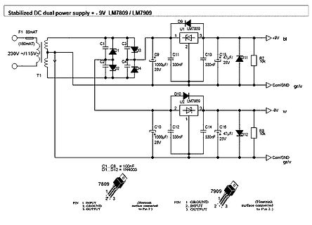
Schaltplan eines stabilisierten dualen DC-Netzteils
Stabilized DC dual power supply + - 9V LM7809 / LM7909 F1 80mA T1 230V ~/115V U1 LM7809 C1 C3 D1 D3 C2 C4 D2 D4 C9 1000uF/25V C11 330nF C13 330nF C15 47uF/25V D11 +9V bl R7 10k Com/GND gr/v D10 U2 LM7909 C10 1000uF/25V C12 330nF C14 330nF C16 47uF/25V D12 -9V w R8 10k
in „Schulprojekt Elektronisch stabilisiertes Netzteil“ · Analoge Elektronik und Schaltungstechnik · · Schaltpläne
-
PDF
LTC3824fg.pdf
Threshold V C= 1.6V 8 % Sense Input Current V SENSE= VCC 0.1 2 µA Oscillator Switching Frequency R SET= 392k: LTC3824E/LTC3824I l 170 200 230 kHz LTC3824MP/LTC3824H l 170 200 240 kHz R SET= 200k l 320 400 460 kHz Synchronization Pulse Threshold Rising Edge VSYNC 1.3 V on SYNC Pin Synchronization Frequency Range R SET= 392k l 230 300 kHz R SET= 200k l 460 600 kHz V R = 392k 1.2 V RSET SET MinimumOn-Time (Measured at GATE Pin) CCMOperation (Note 5) 350 ns Switching Frequency Foldback V FB= 0.3V l 35 50 75 kHz Gate Driver
in „DC/DC Wandler Vin 15-50V, Vout 12V 9A!“ · Analoge Elektronik und Schaltungstechnik ·
-
PDF
IC-MP.pdf
Current in pin VZAP 90 mA G007 Vd() ESD Susceptibbility at all Pins HBM, 100pF discharged through 1.5kΩ 2 kV G008 Tj Junction-Temperature -40 +125 °C THERMAL DATA Operating conditions: VPA, VPD = 5V ±10% Item Symbol Parameter Conditions Unit No. Min. Typ. Max. T01 Ta Ambient temperature -40 125 °C T02 Rthja Thermal resistance chip/ambient package mounted on PCB, thermal pad at 40 K/W approx. 2cm² cooling area All voltages are referenced to ground unless otherwise stated. All currents into the device pins are positive; all currents out of the device pins are negative. ry iC-MP in
in „Analogen Zeigerstand elektronisch ablesen“ · Analoge Elektronik und Schaltungstechnik ·
-
PDF
36ddedx.pdf
test at 85 °C 1000 h: CAP ± 15 % from initial measurement. ESR 1.5 x initial specified limit 36D k = 6.0 at +25 °C, k = 36 at +65 °C, k = 50 at +85 °C DC leakage current I = k CV 36DE, 36DX I in μA, C in μF, V in Volts k = 4.0 at +25 °C, k = 32 at +85 °C DIMENSIONS in inches (millimeters) LARGE CAN
in „Unterschied Bauform "kleiner Elko" "großer Elko"“ · Analoge Elektronik und Schaltungstechnik ·
-
PDF
HMC5883L_3-Axis_Digital_Compass_IC.pdf
7-bit serial address and supports I C protocols. This device supports standard and fast modes, 100kHz and 400kHz, respectively, but does not support the high speed mode (Hs). External pull-up resistors are required to support these standard and fast speed modes. Activities required by the master (register
in „hmc5883l - Winkel berechnen?!“ · Mikrocontroller und Digitale Elektronik ·
-
PDF
HMC5883L_3-Axis_Digital_Compass_IC.pdf
7-bit serial address and supports I C protocols. This device supports standard and fast modes, 100kHz and 400kHz, respectively, but does not support the high speed mode (Hs). External pull-up resistors are required to support these standard and fast speed modes. Activities required by the master (register
-
PDF
MRF272L.pdf
L1 Hairpin Inductor #18 Wire R1 10 k, 1/4 W Resistor C2, C4, C6, C7 1.0–20 pF, Trimmer Capacitor R2 1 k, 1/4 W Resistor C3 15 pF, Mini Unelco Capacitor R3 1.5 k, 1/4 W Resistor C5 47 pF, Mini Unelco Capacitor Z1 0.950″ x 0.250″, Microstrip
-
PDF
Schematics.pdf
9 k 3 IC13A C 3 C 3 1 5 R 2 10k 10k 10k 10k 10k 10k 1 3 43k 43k IC14B R61 2 IC14A TLC272 AD706 TLC272 C94 22k 5 n 9 n 4 n 8 n 2 n 6 n 0 k 5 k C 4 C 3 C 2 C 1 C 1 C 6 R 1 R 4 1n 6 LM7332 R65 R71 R76 R80 R84 R88 7 5 10k 10k 10k 10k 10k 10k GND IC10B GND 1 k GND 6 n 0 n 5 n 9 n 3 n 7 n R 1 C 4 C 3 C 2 C 1 C 1 C 6 R66 R72 R77 R81 R85 R89 5 IC13B C IN2 3 IC11A 10k 10k 10k 10k 10k 10k 7 1 6 2 AD706 LM7332 7 n 1 n 6 n 0
-
PDF
Frequenznutzungsplan2011pdf.pdf
Funkmikrofone bedingungen: Maximal zulässige äquivalente Strahlungsleistung: 50 mW ERP Kanalbandbreite: 200 kHz Frequenznutzungsteilplan: 201 Eintrag: 201002 Stand: AUGUST 2011 Frequenzbereich: 223 - 230 MHz Nutzungsbestimmung(en): 5 31 Funkdienst: RUNDFUNKDIENST 16 Nutzung: ziv, mil Frequenznutzung: Ton-Rundfunk
in „Interessante Frequenzen zwischen 100KHz und 2GHz“ · HF, Funk und Felder ·
-
PDF
2010_05_Stellung_15_erneuerbareStromversorgung.pdf
Parameter zu Pumpspeichern unit 2010 2020 2030 2040 2050 technical parameters roundtrip efficiency kW 0.8 0.8 0.8 0.8 0.8 losses per hour 1/h 0 0 0 0 0 storage capacity in relation to power block size kWh/kW 8 8 8 8 8 availability factor - 0.98 0.98 0.98 0.98 0.98 economic parameters investment costs
-
PDF
Dokumentation.PDF
Resistor 1 R22 30k RESC2012L Res2 Resistor 1 R23 10k RESC2012L Res2 Resistor 1 R24 10k RESC2012L Res2 Resistor 1 R25 10k RESC2012L Res2 Resistor 1 R26 120k RESC2012L Res2 Resistor 1 R27 22k RESC2012L Res2 Resistor 1 R28 10k RESC2012L Res2 Resistor 1 R29 10k RESC2012L Res2 Resistor 1 R30 10k RESC2012L Res2 Resistor 1 R31 6.7k RESC2012L Res2 Resistor 1 R32 6.7k RESC2012L Res2 Resistor 1 R33 3.3k RESC2012L Res2 Resistor 1
-
PDF
PH-1_Phono_preamp.pdf
22781 3313 22.6k 3.32k 0.088938 0.0305 25210 3576 25.5k 3.6k 0.097 0.0333 22546 3278 22.6k 3.3k 0.090396 0.0310 24790 3518 24.9k 3.57k 0.098 0.0336 22316 3245 22.1k 3.24k 0.091854 0.0315 24390 3462 24.3k 3.48k 0.099
in „Kondensatoren für Aikido RIAA“ · Analoge Elektronik und Schaltungstechnik ·
-
PDF
libble-de.pdf
otvor 27 Přístroj nesmíte uvést do provozu dříve, dokud si Symboly na přístroji nepřečtete tento návod k obsluze, nedodržíte všechny pokyny a přístroj nesmontujete předepsaným Před uvedením do Před opravou, způsobem. provozu si přečtěte údržbou nebo tento návod k čištěním vždy Tento návod uchovejte pro
in „Einschalter beim Häcksler defekt?“ · Analoge Elektronik und Schaltungstechnik ·
-
PDF
Nexys4_DDR_schematic.pdf
LA 01 LAN8720A-CP-TRP R1 40 25MHz (100/10LKLD23 LKLD244 R138 DK D13 0C12 I0 R140 10 No Load I0 020K DA B0540WS-7 01uF R212.1K 02R141 12C100 I2 C11 R11399 R1 1% 10K 27pF 27pF 330 R143 PGO D PID140K PID140A No Load No Load No Load RNo Load R230 CD14 GND C B0540WS-7 C NOTE: REF_CLK In Mode ( ETH_REFCLK
-
Datei
spicemodels_zener_diodes.txt
1.00W DIODES INC ZENER *SYM=HZEN .SUBCKT DI_DFLZ10 1 2 * Terminals A K D1 1 2 DF DZ 3 1 DR VZ 2 3 8.86 .MODEL DF D ( IS=41.2p RS=0.773 N=1.10 + CJO=622p VJ=0.750 M=0.330 TT=50.1n ) .MODEL DR D ( IS=8.24f RS=0.230 N=1.49 ) *SRC=DFLZ11;DI_DFLZ11;Diodes;Zener 10V-50V; 11.0V
in „SwCad bzw. Pspice Zener Diode“ · Analoge Elektronik und Schaltungstechnik ·
-
PDF
Trennverstaerker.pdf
1000V notwendig) 1414 V (HCNR201-050, 3 Trafos, alle relevantenAbstände > 6 mm) Stromversorgung: AC 230 V, ca. 2 VA Frequenzgang: +/- 0,09 dBV (+/- 1%) 0 … 34 kHz - 0,3 dBV … 40 kHz - 1 dBV … 56 kHz - 6 dBV … 120 kHz (Signal nur qualitativ beurteilbar) - 20 dBV (-90 %) … 700 kHz (Signal gerade noch erkennbar
in „optischer Trennverstärker mit HCNR201“ · Analoge Elektronik und Schaltungstechnik ·
-
PDF
lm2731.pdf
REVISED SEPTEMBER 2015 100 D1 L1/6.8PH MBR0520 90 3.3 VIN 80 V IN U1 SW ) 70 ( Y 60 R3 LM2731 ‡<· R1/117K 12V N 51K OUT I 50 SHDN FB 230mA I SHDN F 40 (TYP) E GND 30 C1 20 2.2PF R2 CF C2 3.3 -12V 13.3K 270pF 10PF 10 Boost GND 0 ^z_▯s▯ ]}v 0 50 100 150 200 250 LOAD (mA) Figure 36. VIN = 3.3 V, VOUT = 12 V at 230 mA Figure 37. Efficiency vs Load Current 100 L1/10PH MBR0520 9V OUT 90 3.3IN 240mA (typ) VIN U1 SW 80 % 70 R3 LM2731 ‡;· R1/84K Y 60 51K D2 D4 N 3.3 -9V SHDN FB I 50 ^y_▯s▯ ]}v SHDN F 40 GND D3 D5 E
in „[V] 5St. Boost Reg. ADJ TI LM2731XMF 1,6Mhz 1,8A Switch (SOT23-5)“ · Markt ·
-
PDF
M-Series_Details_1_.pdf
with Special Catalog Number. Consult Factory. 3 Requires Branch Circuit Backup with a ULListed type K-5 or RK-5 fuse rated 30Amps maximum 4 Requires Branch Circuit Backup with a ULListed type K-5 or RK-5 fuse rated 60Amps maximum Table B: Lists UL Recognized,CSA Accepted and TUV and VDE Certified configurations
in „Schiffelektrik“ · Offtopic ·
-
PDF
Impulse_CH17_S.65-67.pdf
Die beiden potenziellen Partner Empfindlichkeit min. V 6,2 5,9 Empfindlichkeit min. V 5,9 THD+N (<22kHz) 5W 0,021 0,096 THD+N (<22kHz) 5W 0,084 mit mehr Kanälen haben zwar THD+N (<22kHz) Halblast 0,022 0,069 THD+N (<22kHz) Halblast 0,034 nicht eine so lange Featureliste, Rauschabstand dB(A) 79 84 Rauschabstand
in „SLA-4500 Endstufe Schaltplan gesucht“ · Analoge Elektronik und Schaltungstechnik ·
-
PDF
Wide_Band_Power_Analyzer_System_NORMA_D_6000.pdf
+ 0,0045/kHz ± [(0,04 + 0,0045/kHz) +(0,02+0,0045/kHz)] +(0,01+0,003/kHz)] +(0,02+0,0045/kHz)] +(0,01+0,003/kHz)] 100 kHz...400 kHz +(0,02+0,0045/kHz)] +(0,01+ 0,003/kHz)] typisch: -1,5 % v.Mw/100 kHz 400 kHz..
in „suche Pinning für Einbaukarte Leistungsanalysator Norma D6000“ · PC Hard- und Software ·
-
PDF
Netzfilter-Die_Letzte_Huerde_im_Schaltnetzteil.pdf
gleichgerichtete Netzspannung an. Der Scheitelwert der gleichgerichteten Netzspannung entspricht: 𝑉p= 230V ∙ 2√= 325V (E-1) Exemplarisch wurde ein Schaltnetzteil mit einer Taktfrequenz von 100 kHz herangezogen. Bei dieser Taktfrequenz entspricht die Periodendauer „T“ 10 µs. Die Impulsdauer beträgt 2 µs.
-
PDF
Mabuchi_Motors_Complete.pdf
0.8 ø10.0 26.3 0.7 REF. 5.0 ø5.4 . 9 0 2 8 1 7 ø L . ø3.0 U 4 N 4 HOLES K 3 ER 2 V ø O 2.1 27.2 ø1.2 HOLE F 2.0 R 1 14.0 WEIGHT: 130g (APPROX) 3 CO-241PA-112700 AC 230V, 50Hz CO-241PA-161300 AC 120V, 60Hz P I N P I N 30 0.75 7,500 30 0.75 7,500 20 0.50 5,000 20 0.50 5,000
in „12 V Motor aus der Al-ko Mover Einheit M20 Ams1“ · Fahrzeugelektronik ·
-
PDF
lnk302_304-306-179954-2.pdf
Consumes typically only 50/80 mW in self-powered buck 3. Continuous conduction mode. topology at 115/230 VAC input with no-load (opto feedback) 4. Packages: P: DIP-8B, G: SMD-8B, D: SO-8C. • Consumes typically only 7/12 mW in flyback topology with external bias at 115/230 VAC input with no-load • Meets
in „AC/DC Wandler auf Zeitschaltuhr durchgebrannt“ · Analoge Elektronik und Schaltungstechnik ·
-
Datei
TFT_meters.ino
Comment out lines 153 and 197 to reduce needle flicker and to remove need for Font 4 (which uses ~5k of FLASH!) ######################################################################### ###### DON'T FORGET TO UPDATE THE User_Setup.h FILE IN THE LIBRARY ###### ###### TO SELECT THE FONTS AND PINS YOU
in „2.2'TFT ILI9340 und Arduino“ · Mikrocontroller und Digitale Elektronik ·
-
PDF
ka-user-manual.pdf
On / Of Con tol ● D ita l p nelc o trl ● 4 p r s of p ne se tupsa v / recall Model 110V/120V 220V/230V ● C oarse an f in V tl age / urrent cont rol KA3003D/P T4A/250V T2A/250V FUSE KA3005D/P T5A/250V T3A/250V ● S oft are c libraton ● B eep o tp ut ! KA6002D/P T5A/250V T3A/250V ● bu ton lock u nction
in „RND Labornetzteil“ · Mikrocontroller und Digitale Elektronik ·
-
PDF
SFH229.pdf
Leerlaufspannung Open-circuit voltage Ev = 1000 Ix, Normlicht/standard light A, VO 450 (≥ 400) — mV T = 2856 K Ee = 0.5 mW/cm , λ = 950 nm VO — 420 (≥ 370) mV Kurzschlußstrom Short-circuit current E = 1000 Ix, Normlicht/standard light A, I 27 — A v SC T = 2856 K Ee = 0.5 mW/cm , λ = 950 nm SC — 9 A Anstiegs-
in „Fototransistor im Auto“ · Analoge Elektronik und Schaltungstechnik ·
-
PDF
TempSensorKTY81-120.pdf
Celsius besitzt der KTY81-100 einen minimalen Widerstand von 609 Ohm. R1=2560Ohm−609Ohm=1951Ohm R =2kOhm 1 3) Der Widerstand im Bezug zur Temperatur wird durch folgenden Term beschrieben: 2 Rkty ∗25dT∗adT ∗b R25 ,ist der Widerstand bei 25°C (z.B. 1 kOhm) dT ,ist Differenz zwischen der momentanen Temperatur und 25°C (bei 40°C wäre dT = 15K) -1 a ,ist die Konstante 0,00788 K b ,ist die Konstante 0,00001937 K 4) Der 10bit ADC der AVRs wertet in 1023 Stufen die Spannung zwischen GND und 2,56 V aus. Die Auflösung ist wie folgt zu berechnen
in „Wieviel Strom kann ich aus Aref beziehen?“ · Mikrocontroller und Digitale Elektronik ·
-
PDF
TriacTester.pdf
................................. R5 4701........................................ R1-R3 D1 D2 D3 10k1.............................................. R4 100k1............................................ R6 Test ST3 rot rot 1N4001 A/A2 Kondensatoren: TA1 220μF/25V .................................... C1 ST4 R4 10K Halbleiter: G/G Thyristor-Test TA2 1N4001..........................................D3 ST5 R5 LED, 5 mm, rot ...................... D1, D2 330R K/A1 Triac-Test Sonstiges: 6 0 C1 + R 1 Print-Taster, 1
in „Triac richtig testen“ · Analoge Elektronik und Schaltungstechnik ·
-
PDF
iW1816.pdf
No external compensation components required 12V and above) and capacitve loads up to 6,000μF ●● 64kHz PWM switching frequency ●● Built-in single-point fault protections against output short circuit, output over-voltage, and current-sense- ●● No-load power consumption < 30mW at 230V ACwith resistor
in „Fritz Powerline 540E abgeraucht“ · Mikrocontroller und Digitale Elektronik ·
-
PDF
dms.pdf
Kennwerttoleranz % <"0,20 Temperaturkoeffizient des Kennwertes (TK C) im Nenntemperaturbereich <"0,05 %/10 K im Gebrauchstemperaturbereich %/10 K <"0,10 Temperaturkoeffizient des Nullsignales (T0 ) im Nenntemperaturbereich %/10 K <"0,05 im Gebrauchstemperaturbereich %/10 K <"0,10 Relative Umkehrspanne (d hy
in „DMS auswertung An Atmel 89c51ac2“ · Mikrocontroller und Digitale Elektronik ·
-
PDF
page_883.pdf
80 125 42 150 **) 160 – 160 Bemessungs-Wech- 48 50 – 50 **) 208 200 125 200 sel-/Gleichspannung 220/230/240 250 160 250 Isolierstoff 60 63 – 300 **) 320 – 320 30-60 63 32 380/400/415 400 250 400 100 **) 100 – 440 500 250 400 Verschmut- Mindestkriechstrecke 110 125 – 480/500 500 320 500 zungsgrad K nach
in „Layoutprüfung: Dimmer“ · Platinen ·
-
PDF
20SM47M.pdf
current (uA/2min.)(or less1 A,B size 0.03CV or 1 (whichever is the greater) C,D,E size 0.05CV 5ESR (100k 300kHz) Value in Table 8 or less -55degrees C Z/Z 20degrees C 1.0 2.0 6Temperature characteristics Impedance ratio at 100kHz +105degrees C Z/Z 20degrees C 0.6 1.0 C/C Within 20% High-temperature load
-
PDF
TT-hFE-328-644.pdf
K K 1 3 2 6 2 3 4 6 4 G . a . a . a . a T U F W e F W e F W e F W e O F EI D h S mh S M m h S mh S M m P h C BC558C 458 463 458 4314 pnp BC848AK 135 133 125 853 npn BFX65 531 535 65540 pnp 2N2907 121 120
-
PDF
FC-PA2.pdf
Technische Angaben Technische Daten Mikro-KWK auf Brennstoffzellen-Basis Elektrische Leistung (brutto) kW el 0,75 TV/TR= 50/30 °C Nenn-Wärmeleistung P (Angaben nach EN 50465: 2015) kW 1,1 th max. th TV/TR= 60/40 °C Nenn-Wärmebelastung kW 2,0 Frequenz (erzeugter Strom) Hz 49,5 bis 50,3 Produkt-ID-Nummer
in „Einfamilienhaus ohne Stromanschluss in Deutschland?“ · Haus & Smart Home ·
-
PDF
lcd.pdf
LCD DISPLAY 5 R/W I L 6 E 3 6 1 DB0 O 6 7 DB0 3 0 0 . E R 0 SEG 40 SEG 40 8 DB1 R/W N 0 9 DB2 RS O K 10 DB3 V0 C SIGNAL 4 11 DB4 VDD D SEGMENT DRIVER 12 DB5 GND L 13 DB6 9 14 DB7 0.30 0 A LED BACKLIGHT 15 A K 16 K 9 302-1123 STN 2 x 20 character module RS stock no. 329-0357 65.00 ± 0.50 2.50 60.00 8.50max
in „LCD Zeichen kippen“ · Mikrocontroller und Digitale Elektronik ·
-
Datei
Signalverfolgung.asc.txt
SYMBOL res 560 -80 R90 WINDOW 0 0 56 VBottom 2 WINDOW 3 32 56 VTop 2 SYMATTR InstName R1 SYMATTR Value 5k SYMBOL Misc\\signal 240 -48 R0 WINDOW 3 -109 -38 Left 2 WINDOW 123 0 0 Left 2 WINDOW 39 0 0 Left 2 SYMATTR InstName V1 SYMATTR Value SINE(0 230V 50Hz) SYMBOL Misc\\signal -352 128 R0 WINDOW 3 -299 -64
in „Leitungssucher mit hoher Leistung“ · HF, Funk und Felder ·
-
PDF
TypeManager_Print_Test_Sheet.pdf
61 > 62 ? 63 3 0 1 2 3 4 5 6 7 8 9 : ; < = > ? @ 64 A 65 B 66 C 67D 68 E 69 F 70 G 71H 72 I 73 J 74 K 75 L 76M 77 N 78 O 79 4 @ A B C D E F G H I J K L M N O P 80 Q 81 R 82 S 83T 84 U 85 V 86 W 87X 88 Y 89 Z 90 [ 91 \ 92] 93 ^ 94 _ 95 5 P Q R S T U V W X Y Z [ \ ] ^ _ ` 96 a 97 b 98 c 99d 100 e 101 f 102 g 103h 104 i 105 j 106 k 107 l 108 m 109 n 110 o 111 6 ` a b c d e f g h i j k l m n o p 112 q 113 r 114 s 115t 116 u 117 v 118 w 119x 120 y 121 z 122 { 123 | 124 } 125 ~ 126 127 7 p q r s t u v w x y z { | } ~ € 128 129 ‚ 130
-
PDF
Dot5x7.pdf
61 > 62 ? 63 3 0 1 2 3 4 5 6 7 8 9 : ; < = > ? @ 64 A 65 B 66 C 67D 68 E 69 F 70 G 71H 72 I 73 J 74 K 75 L 76M 77 N 78 O 79 4 @ A B C D E F G H I J K L M N O P 80 Q 81 R 82 S 83T 84 U 85 V 86 W 87X 88 Y 89 Z 90 [ 91 \ 92] 93 ^ 94 _ 95 5 P Q R S T U V W X Y Z [ \ ] ^ _ ` 96 a 97 b 98 c 99d 100 e 101 f 102 g 103h 104 i 105 j 106 k 107 l 108 m 109 n 110 o 111 6 ` a b c d e f g h i j k l m n o p 112 q 113 r 114 s 115t 116 u 117 v 118 w 119x 120 y 121 z 122 { 123 | 124 } 125 ~ 126 127 7 p q r s t u v w x y z { | } ~ € 128 129 ‚ 130
in „Suche Font mit alphanumerischen 5x7/5x8 LCD Zeichen“ · PC Hard- und Software ·
-
PDF
ATXschematics.pdf
obvody (C1, R1, T1, C4, T5) privedeno na usmernovac. Pri napeti 115V se z nej po prepnuti prepinace 230V/115V stane zdvojovac. Varistory Z1 a Z2 maji ochrannou funkci proti prepeti na vstupu zdroje. Termistor NTCR1 slouzi k omezeni proudu pri zapnuti zdroje, nez se nabijou kondenzatory C5 a C6. R2 a R3 slouzi pouze k vybiti zbytkoveho naboje kondenzatoru po vypnuti zdroje. Po pripojeni zdroje k sitovemu napeti se nejdrive nabiji kondenzatory C5 a C6 dohromady asi na 300V. Po te se rozbehne pomocny zdroj rizeny tranzistorem
in „SEPIC-Wandler“ · Analoge Elektronik und Schaltungstechnik ·
-
Datei
Atmega16_vs_Atmega644.cpp
inits.h" #ifdef TWI #include "i2c/i2c_master.h" #include "i2c/i2c_RWRegister.h" #include "i2c/i2c_HT16K33.h" #include "i2c/i2c_buttons.h" #include "i2c/i2c_lcd.h" #include "i2c/i2c_lcd_advanced.h" #include "i2c/i2c_RTC.h" #endif #include "timer_0.h" #include "timer_2.h" #include "countdown.h" #include
in „Umstieg Atmega16 auf Atmega644“ · Mikrocontroller und Digitale Elektronik ·
-
PDF
Triac_Control.pdf
I C: 1 ch) - µPD780034AS 4 ch - 3 ch (UART: 1 ch, 39 - time-division 1.8 V µPD780034A 8 ch 8K to 32K 1 ch 3-wire: 1 ch) µPD780034AY - 8 ch 51 × 3 ch (UART: 1 ch, µPD780024AY 8 ch - I C: 1 ch) 78K0/KB1 8K to 24K 3 ch - 4 ch 22 78K0/KC1 1 ch 3 ch (UART: 2 ch) 32 On-chip 8K to 32K - power-on 78K0/KD1 1 ch - - 39 2.7 V reset 4 ch 1 ch 8 ch 78K0/KE1 8K to 60K 4 ch (UART: 2 ch) 22 2 ch 78K0/KF1 24K to60K 5 ch (UART: 2 ch) 22 × Remark: This table represents a small subsection of the 78K0 8-bit Microcontroller family. Application Note U16498EE1V1AN00
in „Triac ansteuern ohne Moc“ · Analoge Elektronik und Schaltungstechnik ·
-
 Bild
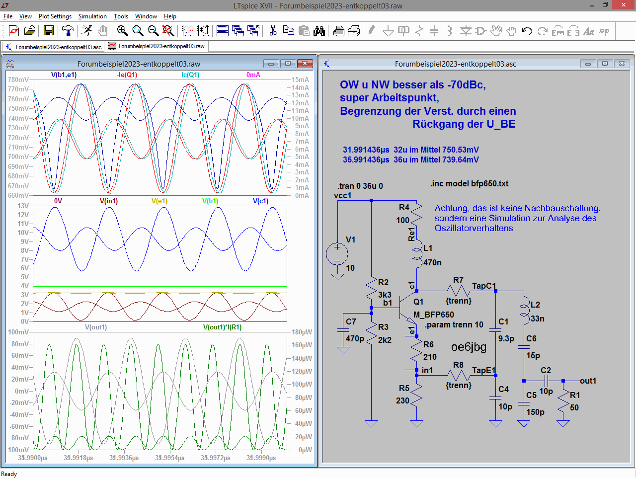
LTspice Simulation eines Oszillators mit Wellenformen und Schaltplan
35.991436us 36u im Mittel 739.64mV .tran 0 36u 0 .inc model bfp650.txt R4 100 V1 Re 1 L1 470n TapC1 R7 3k3 Q1 C7 470p R2 R3 2k2 C1 9.3p L2 33n C6 15p 210 C4 10p C5 150p R8 out1 R1 50 in1 230 R5 TapE1
in „LTspice: Add trace -> geht auch Phasenverschiebung?“ · Analoge Elektronik und Schaltungstechnik · · Screenshots
-
PDF
Datenblatt_Identification_Tischleser_ID_CPR40.30.pdf
max. 140 mA Schnittstelle USB RS232 Schnittstellen - USB Full-Speed (12 MBit/s) - RS232 (4.800bis 230.400 Baud) 5 V DC Optische Signalgeber 2 LED (Grün / Blau) Spannungsversorgung USB Port Powered extern RFID Interface ISO 14443-A/-B - Übertragungsrate 106 … 848 kBit/s - Betriebsfrequenz 13,56 MHz SAM
-
Datei
dt_502813.html
1</td> <td>-4</td> <td>-4</td> <td>-4.000000</td> <td>-4</td> <td>1</td> <td>0</td> <td>0</td> <td>230.0</td> <td>230.000000</td> <td>230.0</td> </tr> <tr> <th>Tobias P. (hubertus)</th> <td>1</td> <td>3</td> <td>3</td> <td>3.000000</td> <td>3</td> <td>0</td> <td>0</td> <td>1</td> <td>1305.0</td> <td>
in „Linux wird nicht wirklich akzeptiert, woran liegt das ?“ · PC Hard- und Software ·
-
Datei
dt_502813.html
1</td> <td>-4</td> <td>-4</td> <td>-4.000000</td> <td>-4</td> <td>1</td> <td>0</td> <td>0</td> <td>230.0</td> <td>230.000000</td> <td>230.0</td> </tr> <tr> <th>korax (Gast)</th> <td>7</td> <td>10</td> <td>-1</td> <td>1.428571</td> <td>5</td> <td>1</td> <td>1</td> <td>5</td> <td>8.0</td> <td>52.142857
in „zukunftsfähige GUI - Qt oder HTML5?“ · Softwareentwicklung ·
-
PDF
VIPower_30W.pdf
374 2.67 6.51 18.2 0.42 1.0 42 BURST Figure 1. Electrical schematic V V 6 T 1 T + R + R % % 1 1 F 6 K 7 K X F R 6 R 4 V X - C V 2 u - C u 1 0 X 2 Y X 5 7 K Y 1 K K F C I 1 C R 2 I u T F T 1 A 0 A A H 2 H C T N F n N 0 E D 4 1 5 D 8 G E P 4 0 C 1 E D P A N D S R 1 N S M O O 4 - M 2 M - 0 - R 3 1 9 0 1
in „Schaltnetzteil - Viper50A-E 45W“ · Analoge Elektronik und Schaltungstechnik ·
-
PDF
ic60.pdf
to 415 V 440 V (Ics) Ph/N (1P, 1P+N) 12 to 60 V 100 to 133 V 220 to 240 V - Rating (In) 0.5 to 4A50 kA 50 kA 50 kA 25 kA 100 % of Icu 6 to 63A 36 kA 20 kA 10 kA 6 kA 75 % of Icu Breaking capacity (Icn) according to IEC/EN 60898-1 Voltage (Ue) Ph/Ph 400 V Ph/N 230 V Rating (In)0.5 to 63A6000A Direct current
in „1000v DC Trennschalter zieht funken.“ · Analoge Elektronik und Schaltungstechnik ·