-
PDF
gesamtinhalt-1967-2019_Call_Heft.pdf
FAX-Empfang Drs. Tjapke Knoeff PAQ 1985/2 104…107 Wettersatelliten Henk Medenblik Ein ATV-Sender für 2,4 GHz Teil 2 B. Sc PE 1 JOK 2000/4 195…210 Amateurfernsehen Henk Medenblik Ein ATV-Sender für 2,4 GHz Teil 2 B. Sc PE 1 JOK 2000/4 195…210 13-cm-Band Ein ATV-Sender für 2,4 GHz Teil 3 Henk Medenblik PE 1 JOK 2001/1 13…30 Amateurfernsehen B. Sc Ein ATV-Sender für 2,4 GHz Teil 3 Henk Medenblik PE 1 JOK 2001/1 13…30 13-cm-Band B. Sc Selbstbau eines Empfängers für GPS & GLONASS
-
PDF
datenblatt_pic.pdf
Figure 2-2. 2: Maintain as clear for upward compatibility with future products. 3: Not implemented. DS35007B-page 12 2001 Microchip Technology Inc. PIC16F84A 3.0 DATA EEPROM MEMORY The EEPROM data memory allows
in „Flußdiagramm Digitale stoppuhr auf PIC 16F84A“ · Mikrocontroller und Digitale Elektronik ·
-
PDF
16F84.pdf
Figure 2-2. 2: Maintain as clear for upward compatibility with future products. 3: Not implemented. DS35007B-page 12 2001 Microchip Technology Inc. PIC16F84A 3.0 DATA EEPROM MEMORY The EEPROM data memory allows
in „Probleme mit Taktversorgung auf Steckbrett“ · Mikrocontroller und Digitale Elektronik ·
-
PDF
trace-elliot-commando-mk-ii-schematics.pdf
TRACE ELLIOT SERVICE MANUAL NO. SM00030 ISSUE 1 Date: February 13, 2001 Product Code : T0152 Model No : Commando MK2 Technical File No :TE00030 Issued by: Trace Elliot Limited. Blackwater Trading Estate The Causeway, Maldon Essex CM9 4GG. C12-PCB-PC00137x4 COMMANDO 100
in „Reparatur Trace Elliot Commando 15“ · Analoge Elektronik und Schaltungstechnik ·
-
 Bild
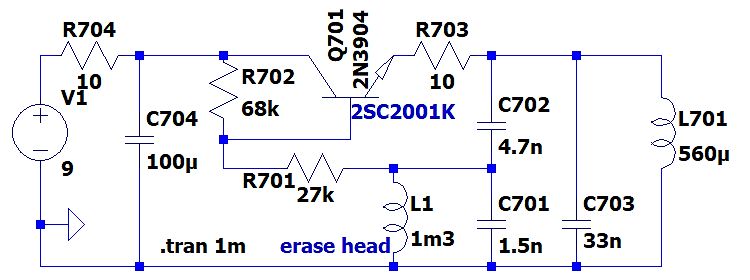
Schaltplan einer Schaltung mit Transistor und Spule
R704 10 V1 9 C704 100µ R702 68k Q701 2N3904 2SC2001K R703 10 C702 4.7n L701 560µ R701 27k L1 1m3 erase head C701 1.5n C703 33n .tran 1m
in „Oszillator, aber welcher“ · HF, Funk und Felder · · Schaltpläne
-
 Bild
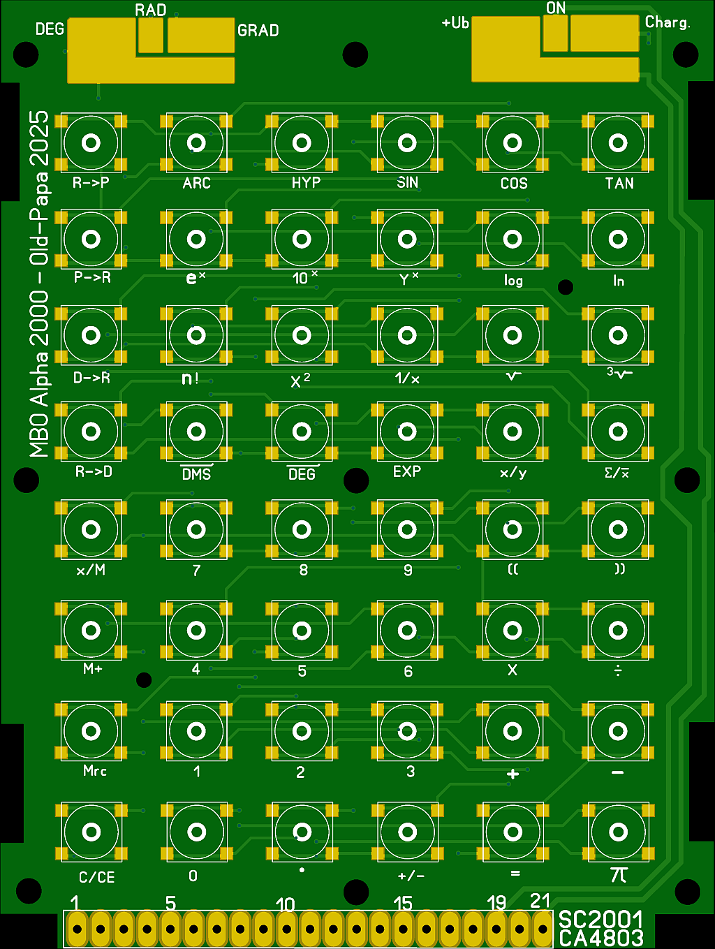
Leiterplatten-Layout einer Taschenrechner-Tastatur
Ub ON Charg. MBO Alpha 2000 Old-Papa 2025 R->P ARC HYP SIN COS TAN P->R e* 10* Y* log ln D->R n! x^2 1/x √ 3√ R->D DMS DEG EXP x/y Σ/x x/M 7 8 9 ( ) M+ 4 5 6 X ÷ 1 2 3 + Mrc C/CE 0 10 +/- = π 1 5 15 19 21 SC2001 CA4803
in „Suche Datenblatt zu sehr altem Taschenrechnerschaltkreis (Mitsubishi)“ · Mikrocontroller und Digitale Elektronik · · Layouts
-
PDF
grundig32zollLedTV.pdf
_P J2 A_RX2N LINE_IN_1R R3 100NF HDMIA HDMIA-RX2_P A_RX2P LINE_IN_2L P2 SCART_AUDIO HDMIA-CLK_N HDMIA-CLK_N F1 A_RXCN LINE_IN_2R N6 SC-Lin HDMIA-CLK_P HDMIA-CLK_P G3 A_RXCP LINE_IN_3L N7 SC-Rin SC-Lin HDMIA-SCL
in „Reparaturbericht LED-TV Grundig 32 VLE 5620 BN Ton gut, aber kein Bild“ · Analoge Elektronik und Schaltungstechnik ·
-
 Bild
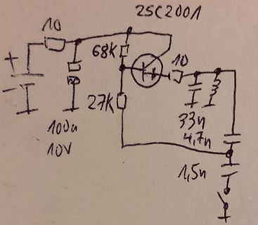
Handgezeichneter Schaltplan mit Transistor
2SC2001 10 68K 10 27K 100u 10V 33u 4,7n 1,5n
in „Oszillator, aber welcher“ · HF, Funk und Felder · · Fotos
-
 Bild
Ausschnitt eines Schaltplans
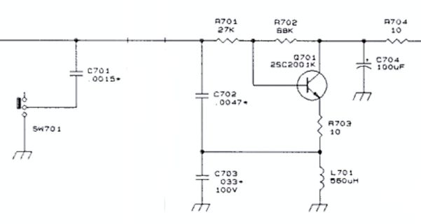
A701 27K R702 88K A704 10 C704 100uF Q701 2SC2001K R703 10 L701 560uH C703 033 100V C702 .0047 SW701 C701 .0015
in „Oszillator, aber welcher“ · HF, Funk und Felder · · Schaltpläne
-
PDF
ucc37324.pdf
4.5 A at VDD = 15 V and 4.28 A at V DD = 12 V. VDD UCC37323 INPUT 1 8 DSCHOTTKY INA OUTA 10Ω 2 7 C2 C3 + VSUPPLY 3 GND VDD 6 1 µ 100µF 5.5 V INB OUTB 4 5 VSNS RSNS 1µF 100µF 0.1Ω CER AL EL UDG−01065 Figure 2. www.ti.com 7 SLUS492B − JUNE 2001 − REVISED SEPTEMBER 2002 APPLICATION INFORMATION The
in „Wofür einen Mosfet Treiber?“ · Analoge Elektronik und Schaltungstechnik ·
-
PDF
tl431.pdf
2 VKA = Vref, KA = 10 mA 2470 2495 2520 mV SOT23-3, SC-70, Deviation of reference voltage VKA = Vref, 14 34 VI(dev) over full temperature range 2 IKA = 10 mA, and TL432 devices mV (see Figure 1) TA= −40
in „Sicherung bei überschreiben von VCC auslösen, wie?“ · Analoge Elektronik und Schaltungstechnik ·
-
PDF
tl431.pdf
2 VKA = Vref, KA = 10 mA 2470 2495 2520 mV SOT23-3, SC-70, Deviation of reference voltage VKA = Vref, 14 34 VI(dev) over full temperature range 2 IKA = 10 mA, and TL432 devices mV (see Figure 1) TA= −40
in „bauelement für Spannungsdurchlass“ · Analoge Elektronik und Schaltungstechnik ·
-
PDF
PSpice_LibraryguideOrCAD.pdf
JBIPOLAR.OLB Bipolar Transistor 2SC1940 Q2SC1940 JBIPOLAR.OLB Bipolar Transistor 2SC1941 Q2SC1941 JBIPOLAR.OLB Bipolar Transistor 2SC1959 Q2SC1959 JBIPOLAR.OLB Bipolar Transistor 2SC1980 Q2SC1980 JBIPOLAR.OLB Bipolar Transistor 2SC2001 Q2SC2001 JBIPOLAR.OLB Bipolar Transistor 2SC2002 Q2SC2002 JBIPOLAR.OLB Bipolar Transistor 2SC2003 Q2SC2003 JBIPOLAR.OLB Bipolar Transistor 2SC2188 Q2SC2188 JBIPOLAR.OLB Bipolar Transistor 2SC2206 Q2SC2206
in „pSpice - Bauteil hinzufügen.“ · Analoge Elektronik und Schaltungstechnik ·
-
PDF
GPS-Compendium_Book__GPS-X-02007_.pdf
.................................................................................. 131 8.2.2 Conversion from NMEA to KML ................................................................................................ 142 8.2.3 The DGPS correction data (RTCM SC-104)........................
in „Verschlüsselte Militär(?)daten innerhalb des GPS-Signals“ · HF, Funk und Felder ·
-
PDF
slyt309.pdf
flyback. Planet given in Equation 13: Analog [Online]. Available: http://www.planetanalog.com/ P = I2 × r × D(max)+ I showArticle.jhtml?articleID=177103753 D_Q1 Q1(RMS) DS(on) Q1(Peak) t + t (13) Related Web sites × IN(min)+ VOUT + VFW D × Rise Fall× SW , power.ti.com 2 www.ti.com/sc/device/TPS61170
in „Gleichspannungswandler in Reihe schalten“ · Analoge Elektronik und Schaltungstechnik ·
-
PDF
Darlington_BST5x.pdf
complements: BST60, BST61 and BST62. MARKING 3 2 1 1 sym080 TYPE NUMBER MARKING CODE BST50 AS1 BST51 AS2 Fig.1 Simplified outline (SOT89) and symbol. BST52 AS3 ORDERING INFORMATION PACKAGE TYPE NUMBER NAME DESCRIPTION VERSION BST50 SC-62 plastic surface
in „Transistor für hohe Frequenz und hohe Leistung gesucht“ · Mikrocontroller und Digitale Elektronik ·
-
PDF
dbsht1x7xdeutschdk0704.pdf
das Interface vollständig auf statischer Logik basiert 9GG gibt es keine Mindest-SCK. *1' XC '$T$ 2 SHT 1x ▯ ▯▯▯▯▯▯ 6HULDO▯GDWD▯▯'$7$▯▯ ▯PDVWer▯ 3 ▯VODYe▯ SC. 4 'HU▯ '$7$▯ 7ULVWDWH▯3LQ▯ ZLUG▯ I U▯ GDV▯ $XVOHVHQ▯ GHU▯ 'DWHQ▯ 9GG 2▯4 - 5▯59 YHUZHQGHW▯▯DATA ändert sich nach der fallenden Flanke ▯ Abb
in „Auswertung Luftfeuchtesensor“ · Mikrocontroller und Digitale Elektronik ·
-
PDF
antenna-impedance-models.pdf
can more network complexity buy? Series RLC Equivalent Circuit for Dipoles at Resonance 1 Zin + sL R sC LCs 2+RCs + 1 1 resonanceole = R = 72.3 Cs L = 2µH9 2 R 1 C = 39.8 pF s + s + jω = L L LC s quadratic = pole a× ∞ σ linear Accuracy of Series RLC Model Parallel RLC Equivalent Circuit for Dipoles at
in „Endstufe für schwankende Lastimpedanz“ · Analoge Elektronik und Schaltungstechnik ·
-
PDF
BTS711L1_20030919.pdf
short circuit shutdown time toff(SC) f j,start; bb =12 V t [msec] off(SC) 6 5 4 3 2 1 0 -50 0 50 100 150 200 Tj,start°C] Semiconductor Group 11 2003-Oct-01 BTS711L1 Timing diagrams Timing diagrams are shown for chip 1 (channel 1/2). For
in „Beleuchtungsüberwachung KFZ“ · Mikrocontroller und Digitale Elektronik ·
-
PDF
BTS711L1_20030919.pdf
short circuit shutdown time toff(SC) f j,start; bb =12 V t [msec] off(SC) 6 5 4 3 2 1 0 -50 0 50 100 150 200 Tj,start°C] Semiconductor Group 11 2003-Oct-01 BTS711L1 Timing diagrams Timing diagrams are shown for chip 1 (channel 1/2). For
in „High-Side 8-fach FET/Transistor Array bei 12V und 1A“ · Analoge Elektronik und Schaltungstechnik ·
-
PDF
tle2082.pdf
AMPLIFIERS SLOS182B – FEBRUARY 1997 – REVISED JUNE 2001 PARAMETER MEASUREMENT INFORMATION 2 kΩ 10 kΩ V VCC+ CC+ 2 kΩ 100Ω VI – VI – + V O + VO V VCC+ R † CC+ R † L CL L C L †Includes fixture capacitance †Includes fixture capacitance Figure 1. Slew-Rate Test
in „Bauteil gesucht: unbekannter TI-Baustein“ · Mikrocontroller und Digitale Elektronik ·
-
PDF
TMS320F2812_Datasheet.pdf
9 10 11 12 13 14 Figure 2−1. TMS320F2812 and TMS320C2812 179-Ball GHH MicroStar BGA (Bottom View) 14 SPRS174O April 2001 − Revised July 2007 Introduction 2.3.2 Pin Assignments for the PGF Package The TMS320F2812 and TMS320C2812
in „Wieder eine Elektronik-Anfängerfrage“ · Mikrocontroller und Digitale Elektronik ·
-
PDF
ucc28c43.pdf
controller and UCC3961 as the primary-side startup control device. 9 www.ti.com SLUS458D − AUGUST 2001 − REVISED JANUARY 2007 APPLICATION INFORMATION 5 F + C 1 2 0 R 1 D 1 F L 2 1u 1 C .0 C D 8 V G Z 3 R B 3 2 F P C 1 0 1 u C 1 F + 3 2 C 2 0 6 u 2 u + 2 7 C 2 8 7 6 5 C 4 F c T D E c U N R V O G F 1 u
in „SNT will nicht anlaufen - falsches TI Datenblatt?“ · Analoge Elektronik und Schaltungstechnik ·
-
PDF
18000-1.pdf
M2-P:1 Who talks first M2-P:2 Tag addressing capability M2-P:3 Tag UID M2-P:3a UID length M2-P:3b UID format M2-P:4 Read size M2-P:5 Write size M2-P:6 Read transaction time M2-P:7 Write transaction time
in „RFID Controller programmieren“ · Mikrocontroller und Digitale Elektronik ·
-
PDF
6291174.pdf
2SC2812-L6-TB 405 015 8902 TR 2SC2812-L7-TB 405 015 8902 TR 2SC2812-L7-TB 405 163 1602 TR 2SC2812N-L6-TB0 405 163 1602 TR 2SC2812N-L6-TB0 405 163 1701 TR 2SC2812N-L7-TB0 405 163 1701 TR 2SC2812N-L7-TB0
in „Sanyo LCD Beamer PLC- XU30 defekt“ · Analoge Elektronik und Schaltungstechnik ·
-
PDF
Schaltplan.pdf
. TO92 Q23B D29B 14 BC560C 0 6873 2 WR P 14 R54B 1 TO126 1 / 9L MR854 1/4W Q10B 0 B R 1 3F D31B 47K 5102 B 4 8 W 249 / 2SC5949-0 D30B MINI 8 0 R 11 Q25B R122B TO92 8 B C 1 C29B 1/2W MR854 MR854 0 1 3 2 1 7005 220N 250V 1R 5 7 WR M 4 D
in „Funktion Protectschaltung“ · Analoge Elektronik und Schaltungstechnik ·
-
Datei
Report_Samsung_X20.htm
WIDTH=16><TD WIDTH=16><TD WIDTH=16><TD WIDTH=16> <TR><TD><TD CLASS=dt COLSPAN=5>[ FUJITSU MHZ2320BH G2 ] <TR><TD> <TR><TD><TD><TD COLSPAN=3><B>Geräteeigenschaften:</B> <TR><TD><TD><TD><TD>Gerätebeschreibung <TD>FUJITSU MHZ2320BH G2 <TR><TD><TD><TD><TD>Treiberdatum <TD>01.07.2001
-
PDF
0900766b80c827e9.pdf
INA332 A2N N23 ® 32 INA2332 SBOS216B – SEPTEMBER 2001 - REVISED OCTOBER 2006 Low-Power, Single-Supply, CMOS INSTRUMENTATION AMPLIFIERS FEATURES APPLICATIONS ● DESIGNED FOR LOW COST ● INDUSTRIAL SENSOR AMPLIFIERS
in „Magnetfeldsensor mit LED Display“ · Mikrocontroller und Digitale Elektronik ·
-
PDF
BTS462T_20040127.pdf
: D=t /T p 10 2 10 2 K/W K/W D=0.5 D=0.5 D=0.2 1 D=0.2 1 D=0.1 10 10 D=0.1 D=0.05 J J t D=0.05 t Z Z D=0.02 0 D=0.02 0 D=0.01 10 10 D=0.01 10-1 10-1 D=0 D=0 10-2 10-2 10 10 106 -10 10 103 -10 10 10 1 102 s 104 10 10
in „Schaltregler-Diskussion“ · Analoge Elektronik und Schaltungstechnik ·
-
PDF
behringer_eurolive_b112d_sm.pdf
*08-02-B-ZP-SLV[R] 1 13 10 F88-30080-50297 SC-M03*08-05-B-ZP-BLK[R] 2 9 F96-30400-80080 SC-WATEIN4*8*0.8[R] 1 8 F88-30100-30217 SC-A03*10-03-B-ZP-BLK[R] 10 7 G52-00100-13392 PLASTIC ROTARY KNOB (430C);I00470P;CAP:WHITE 2 6 G52-00100-13393 PLASTIC
in „Behringer B112D Funktionsweise Netzteil“ · Analoge Elektronik und Schaltungstechnik ·
-
PDF
c01609323.pdf
ITU-T T.31 class 1 FAX, V. 17, V.29, V.27ter, and V.21 Channel 2 Error Correction and V.44, 42bis, V.42 and MNP2-5 Data Compression Power Management ACPI; PPMI 1.1 and wake support with PME and Vaux; meets PCI 2.3 requirements and PC 2001 requirements Upgradeability
in „PC bootet nicht nach cpu Tausch“ · PC Hard- und Software ·
-
PDF
hm3036.pdf
+12V --> 14 ¯SR5¯ --> 2 HT-1 --> 15 ¯XY¯ --> 16 ¯SR10¯ --> 3 -2kV --> 4 FOCUS --> 17 ¯SC2¯ YP-Board (J2007) and TB-Board (J4007) --> 18 ¯SH0¯ --> 19 ¯SC3¯ Direction Pin Name --> 20 T_VAR --> 1 ¯CT¯ --> 21 ¯X_MAG¯ PS-Board (
in „HM303-6 Schaltpläne“ · Analoge Elektronik und Schaltungstechnik ·
-
PDF
Hameg_HM303-6_Service_manual.pdf
+12V --> 14 ¯SR5¯ --> 2 HT-1 --> 15 ¯XY¯ --> 16 ¯SR10¯ --> 3 -2kV --> 4 FOCUS --> 17 ¯SC2¯ YP-Board (J2007) and TB-Board (J4007) --> 18 ¯SH0¯ --> 19 ¯SC3¯ Direction Pin Name --> 20 T_VAR --> 1 ¯CT¯ --> 21 ¯X_MAG¯ PS-Board (
in „Hameg 303-6 Schaltplan + PCB.“ · Analoge Elektronik und Schaltungstechnik ·
-
PDF
Under_the_Hood_of_Flyback_SMPS_Designes_slup261__TI.pdf
contributionissubtractedfromtheerroramplifier’s Fig.A-1, K ffcan be calculated as: output V c so that it becomes easier to define the R scR(R S) duty-cycle equation. This representation is functionally equivalent to adding the feedforward K = R sc+R S to the current feedback. ff R scR+( S) (A-2) The equation of the output load-current limit +R ff R sc+R S = R scR(R S) . R × R+( +R × R)+R+R ( ) s⋅ S ff sc S VC K ff i R S Ipk RS× m 2 RS× R × m RS× IA MaCurrent)g S 1 D × Ts Gate Control Fig. A-3. Peak CMC law: No parasitic or filter delays, no slope
in „Flyback-Wandler Störungen auf Versorgung“ · Analoge Elektronik und Schaltungstechnik ·
-
PDF
BTS4140N.pdf
current limit Typ. initial short circuit shutdown time IL(SCp) = f(T j ; V bb = 13,5 V; t =m100 µs toff(SC) = f(T j,start 3 1 10 ms A 102 p C C ( L o I 0.6 t 101 0.4 0 10 0.2 13,5V 24V 42V 0 10 -1 -40 -20 0 20 40 60 80 100 120 °C 160 -40 -20 0 20 40 60 80 100 120 °C 160 Tj T j Typ. initial peak short circuit current limit Typ. current limitation characteristic: IL(SCp) = f(V bb); tm= 100 µs IL(SC) = f(V ON ), Vbb = 13,5V 1.2 1 A -40°C A 25°C p ) S 0.8 S L L I 150°C I 0.6 0.6 0.4 0.4 0.2 0.2 0 0 0 5 10 15 20 25 30 35 40 V 50 0 4 8 12 16 V 24 V V bb ON Page 14 2004-01-27 BTS 4140 N Typ. standby
in „+12V mit +3.3V schalten P-MOSFET?“ · Analoge Elektronik und Schaltungstechnik ·
-
PDF
Part_1_Physical_Layer_Specification_Ver3.01_Final_100218.pdf
2001-2010 SD Group (Panasonic, SanDisk, Toshiba) and SD Card Association Physical Layer Specification Version 3.01 c 5.3.2 CSD Register (CSD Version 1.0) n Name Field Width Value Type CSD-slice CSD structure
in „MicroSD STM32 und Mosfet“ · Mikrocontroller und Digitale Elektronik ·
-
PDF
kicad_8450_dcm_liste_neu_v3.pdf
Dropout Voltage Regulator, Fixed Output 2.1V, SC-70-4 APE8865U4-22-HF-3 300 mA Low Dropout Voltage Regulator, Fixed Output 2.2V, SC-70-4 APE8865U4-23-HF-3 300 mA Low Dropout Voltage Regulator, Fixed Output 2.3V, SC-70-4 APE8865U4-24-HF-3 300
in „KiCAD Eeschema, Bibliotheksdokumentation *.dcm als PDF-Datei“ · Platinen ·
-
PDF
vig_2008.pdf
f Max { 2.9 x 10 per gram for an AT-cut resonator Δf -8 f 1.7 x 10 per gram for an SC-cut resonator Min 0 at = 61 for an AT-cut resonator, and at = 82 for an 4-13 SC-cut. Bonding Strains Induced
in „Was ist drin im Quarzoszillator?“ · Analoge Elektronik und Schaltungstechnik ·
-
PDF
07565269.pdf
whichareobtained 6 . i . 2 d 2 3 1 i duringregistration IdM 3.3. partial identityAuthentication IoT service resolution verification andprovisioningstage. i t Thisfunctionalityis a d n i t i i Bootstrapping carriedoutbythe m ni
in „Wissenschaftiches Vorgehen/Methoden bei These-Antithese-Synthese“ · Ausbildung, Studium & Beruf ·
-
PDF
RTX1040ProductSpecification_v2.5.pdf
to change said content, circuitry and specifications. at the time of Product Specification Figure 2: Module solder point specification. Item Specification Note Weight 8 g PCBA = 5 g, RF shield = 3 g 4 Hardware Specification The design is based on the following main components: Module Transceiver SC14441
in „Falls jemand eine Fernsteuer-App fürs Handy sucht.“ · Haus & Smart Home ·
-
PDF
slac-pub-13410.pdf
-TO247 package (gate: CH1, drain: CH2) and (b) PCB#2-hybrid circuit (gate: CH2, drain: CH1). Charge voltageload 10.6 Ω. Figure 5. Switching time verses charge voltage as a function of driver Vss+. RLoad 27 Ω Work supported by the U.S. Department
in „SiC MOSFET schnell (28 MHz) schalten“ · HF, Funk und Felder ·
-
PDF
M43T.pdf
EE CATHODE 3 4 GND 0.4 ± 0.05 (0.016 ± 0.002) 3.6 ± 0.1* (0.142 ± 0.004) 0.102 ± 0.102 0.20 ± 0.025 2.5 ± 0.1 (0.004 ± 0.004) (0.008 ± 0.001) (0.098 ± 0.004) 7 MAX. 1.27 0.71 (0.050)SC (0.028)IN. MAX. LEAD COPLANARITY DIMENSIONS IN MILLIMETERS (INCHES) = 0.102 (0.004) * MAXIMUM MOLD FLASH ON EACH SIDE
in „Optokoppler Berechnung max. Übertragungsfrequenz“ · Mikrocontroller und Digitale Elektronik ·
-
PDF
rf__0_4_schem.pdf
L6L6 100nF P I U 2 1B4 S0 P I U 2 0 1 4 4 13 PIC402 PIC401 PIC1201 PIC1202 PIPIL602 PIC2002 PIC2001 4 13 P I U 1 1B3 2B4 P I U 1 0 1 3 100nF 20 390 2.2uH 02 P I U 2 1B3 2B4 P I U 2 0 1 3 P I U 1 0 5 P I U 1 0 1 2 81CO8
-
PDF
SerProg.pdf
interface connector” was used only in Chapter 4. ] the “Warranty and Disclaimer” was updated 31.07.2001 Several minor errors corrected from V2.4. V2.5 02.01.2002 Several minor errors corrected from V2.5. V2.6 13.01.2003 In Command line parameters: new command line parameter V2.7 CPU Operating Mode after
in „Fujitsu MB91F011 internal flash read/write“ · Mikrocontroller und Digitale Elektronik ·
-
PDF
TMC4671-EVAL_Schematic.pdf
SC S 5 6 P DBG_SPI_TRG S P I1[3C], 2[2C] 10k CXTL2 00 1[3C], 2[2C]0 DBG_SPI_SCK C K PP7005 PI8006 1[3C], 2[2C] SDBG_SPI_MOSIS I PP2007 PI2008 PIT200 GND OUT PXT20P CLK25 L 1[1B], 2[1A] 1[3C], 2[2C] SDBG_SPI_MI
-
PDF
Schieberegister_SN74HC595_Datenblatt.pdf
R 3S 2S 2R 3R 2 C2 C3 Q C R 3S 2S 2R 3R 3 Q C2 C3 D R 3S 2S 2R 3R 4 C2 C3 Q E R 3S 2S 2R 3R 5 C2 C3 Q F R 3S 2S 2R 3R 6 C2 C3 Q G R 3S 2S 2R 3R C2 C3 7 Q H R 3S 9 Q H′ Pin numbers shown are for the D, DB, DW
in „Auswahl Schalterarray“ · Mikrocontroller und Digitale Elektronik ·
-
PDF
tl431.pdf
packing quantities, thermal data, symbolization, and PCB design guidelines are available at www.ti.com/sc/package. ‡ DBV: The actual top-side marking has one additional character that designates the assembly/test site. 2 POST OFFICE BOX 655•DALLAS, TEXAS 75265 TL431, TL431A ADJUSTABLE PRECISION SHUNT REGULATORS
in „Spannungsteiler hohe oder niedrige Widerstände besser?“ · Analoge Elektronik und Schaltungstechnik ·
-
PDF
UKW_Berichte_1963_2019.pdf
1 41…48 Software Fundstelle Internet Gunthard Kraus DG 8 GB 2001/1 59…60 Internet Fundstelle Internet Gunthard Kraus DG 8 GB 2001/2 123…124 Internet Das interessante Programm: TRL85.EXE Gunthard Kraus DG 8 GB 2001/2 73…79 Software Moderner Entwurf von Streifenleitungs-Bandpässen aus gekoppelten Lei- Gunthard Kraus DG 8 GB 2001/2 97…121 Grundlagen tungspaaren Moderner Entwurf von Streifenleitungs-Bandpässen aus gekoppelten Lei- Gunthard Kraus DG 8 GB 2001/2 97…121 Wettersatelliten tungspaaren Moderner Entwurf von Streifenleitungs-Bandpässen