-
PDF
limestone_arm_pda_pxa320_datasheet.pdf
www.torldex.com info@tlradex.com 4 Limestone Datasheet 1.3 Features CPU Marvell PXA320 806 MHz Memory 128 Mbyte of DDR SDRAM (32 Bit) 1Gbyte of NAND FLASH (8 Bit) Power Supplies 5VDC Li-Ion Battery On-Board Features Li-ion/Li-Polymer Battery Charger Fuel Gauge High Quality Audio I/O (16 Bit stereo) USB
in „[V] Toradex Limestone Marvell PXA320 Processor Board (8€)“ · Markt ·
-
PDF
XPort_reference_design_and_guidelines.pdf
Down to 1V Dropout • Guaranteed Dropout Voltage at Multiple Current Levels • 0.2% Line Regulation Max • 0.4% Load Regulation Max The following is a reference design for using the LT1117 part. See the XPort reference design for further details 3.3 V SM4007 Vin Vout +5V LT1117 270 Input Voltage Regulator
in „Lantronix X-Port beschalten“ · Mikrocontroller und Digitale Elektronik ·
-
PDF
DGF-12232-S1FBLY-325-17231-1006.pdf
Dot spacing (mm) 0.04 Module dimensions (Horizontal × Vertical × Thickness, mm) 84.0 × 44.0 × 10.5max. Viewing area (Horizontal × 60.5 × 18.5 Vertical, mm) Active area (Horizontal × Vertical, mm) 53.64 × 15.64 DATAVISION 06/01/11 3 / 25 SPECIFICATIONS FOR LIQUID CRYSTALDISPLAY MODULE MODELNO: DGF-12232
in „Datenbild für LCD“ · Mikrocontroller und Digitale Elektronik ·
-
Datei
rfm70.h
*******************RFM Definitions************************************************// #define RFM70_MAX_PACKET_LEN 32// max value is 32 #define RFM70_BEGIN_INIT_WAIT_MS 3000 // pause before Init Registers #define RFM70_END_INIT_WAIT_MS 100 // pause after init registers #define RFM70_CS_DELAY 0 // wait
in „Referenzparameter richtig übergeben“ · Mikrocontroller und Digitale Elektronik ·
-
PDF
BCR191-INF.pdf
Collector current IC 100 mA mW Total power dissipation- Ptot BCR191, T ≤ 102°C 200 S BCR191F, TS≤ 128°C 250 BCR191W, T S 124°C 250 Junction temperature Tj 150 °C Storage temperature Tstg -65 ... 150 1 2007-07-31 BCR191... Thermal Resistance Parameter Symbol Value Unit 1) Junction - soldering point R
in „Comparator LM393 to uC“ · Analoge Elektronik und Schaltungstechnik ·
-
Datei
stack_c.h
count++) { index_tmp = arp_entry_search(dest_ip_store); index = arp_entry_search(dest_ip); if (index < MAX_ARP_ENTRY || index_tmp < MAX_ARP_ENTRY) { DEBUG("ARP EINTRAG GEFUNDEN!\r\n"); if (index_tmp < MAX_ARP_ENTRY) return(1);//OK arp_entry[index].arp_t_ip = dest_ip_store; return(1);//OK } for(a=0;a<10000
in „Webpage Webserver“ · Mikrocontroller und Digitale Elektronik ·
-
Datei
test.c
/* * XMEGA128A1 Testboard * * @file test.c * @brief Soundausgabe über Xmega DAC mit DMA / Events / Timer. Lesen der Samples von SD Card mit DMA. * @author KaiO * @date Jan 31, 2010 * * * * Sounds * ------ * Finden
in „Xmega Soundcheck“ · Mikrocontroller und Digitale Elektronik ·
-
Datei
CAPTURE.TXT
modify handler fastpath (31 instructions). cause = 40808000, status = 11000000 PID hash table entries: 128 (order: 7, 512 bytes) calculating r4koff... 001e8480(2000000) CPU frequency 500.00 MHz Using 250.000 MHz high precision timer. Dentry cache hash table entries: 4096 (order: 2, 16384 bytes) Inode-cache
in „Plunder von Pollin:WMDR-143N“ · Mikrocontroller und Digitale Elektronik ·
-
Datei
mmc.c
Pause für Power-up { nop(); } SPCR = (1<<SPE)|(1<<MSTR)|(1<<SPR1)|(1 << SPR0); // SPI-Bus einstellen - max. 400kHZ SPSR &= ~(1 << SPI2X); // Clock / 128 for (uint8_t a = 0; a<=0x0f; a++) // Zeit für Start-up { writebyte (0xff); } // CMD0 - GO_IDLE_STATE senden uint8_t timeout = 0; uint8_t CMD [] = {0x40,
in „MMC/SD Adresse“ · Mikrocontroller und Digitale Elektronik ·
-
Datei
FanController.c
USART_RXC_vect) { uint8_t temp = UDR; if(temp == 'x') { sendRpm = 1; } else if(temp == 'y') { OCR1A = 128; } else if(temp == 'z') { OCR1A = 0; } } ISR(INT0_vect) { if(!lockRpm) { if(!timer0_overflow_error) { stopTimer0(); rpmTemp = timer0_overflows<<8; rpmTemp |= TCNT0; } else { rpmTemp = 0; } } resetTimer0
in „Problem mit c Programm ATmega32“ · Mikrocontroller und Digitale Elektronik ·
-
Datei
main.cpp
#include <avr/io.h> #include <stdint.h> #include <arduino.h> #define MAX_LINES 10 #define NO_INPUT 0 #define DIGITAL_INPUT 1 #define ANALOG_INPUT 2 #define PWMFreq 720 // output PWM frequency (Hz) uint16_t ICR16Val; void setup() { int i; ICR16Val = 16000000/PWMFreq/2; //
in „Arduino Mega R3 PWM funktioniert nicht für Timer 5 (A), Pin 44“ · Mikrocontroller und Digitale Elektronik ·
-
PDF
hxk80aa_cdo00096_r600a_220v_50hz_12-2016_desd564p102.pdf
indication Frequency Hz 50 60 Evaporating temperature °C -35 to -5 – Voltage range V 187 to 264 – Max. condensing temperature continuous (short) °C 60 (70) – Max. winding temperature continuous (short) °C 130 (130) – S = Static cooling normally sufficient Cooling requirements O = Oil cooling Frequency
-
PDF
ATMega164_324_644_1284pa.pdf
by either ICRn or OCRnA. The minimum resolution allowed is 2-bit (ICRn or OCRnA set to 0x0003), and 128 8272C–AVR–06/11 ATmega164A/PA/324A/PA/644A/PA/1284/P the maximum resolution is 16-bit (ICRn or OCRnA set to MAX). The PWM resolution in bits can be calculated using the following equation: R = -----
in „Hilfe bei AD-Wandler!“ · Mikrocontroller und Digitale Elektronik ·
-
PDF
DiskOnChip_Mil._DS_Rev2.1.pdf
Sectors cascaded Capaci1y under D2S 6.22 under DOS devices (bytes) (bytes) 6.22 3 8,151,040 15,920 8,128,512 15,876 MD2800-D08 (DIP) None MD2810-D08 (TSOP) 1 8,151,040 15,920 8,128,512 15,876 MD2810-D08 (TSOP) 2 16,375,808 31,984 16,324,608 31,884 3 24,592,384 48,032 24,516,608 47,884 MD2810-D08 (TSOP)
in „Pollin Netbox“ · Mikrocontroller und Digitale Elektronik ·
-
PDF
CH454DS1.PDF
a built-in clock oscillation circuit, which can dynamically drive 8 16-segment LED Nixie tubes or 128 LEDs, support 11-segment, 14-segment, 16-segment × 8 and 17-segment ×7, etc. and can also scan the keyboard with 64 keys. CH454 exchanges data with a MCU through a 2-wire serial interface. XSG7~XSG0
in „Viele Drucktaster und LEDs ansteuern“ · Mikrocontroller und Digitale Elektronik ·
-
PDF
REN_r01ds0145ej0102_v850e2fe4l_DST_20140421.pdf
characteristic measurement condition AC test input waveform xVDD VIH (min) Measurement VIH (min) xVSS VIL (max) VIL (max) AC test output waveform xVDD VOH (min) Measurement VOH (min) xVSS VOL (max) VOL (max) Standard AC test condition is 70%/30% of the applied IO supply voltage (XmVDD) if not otherwise stated
in „Renesas V850 (3572 (A2) FE4-L) auslesen / programmieren?“ · Mikrocontroller und Digitale Elektronik ·
-
Datei
u-boot.cfg.txt
#define CONFIG_ARCH_MEDIATEK 1 #define CONFIG_REGEX 1 #define CONFIG_EFI_PARTITION_ENTRIES_NUMBERS 128 #define CONFIG_SYS_CONFIG_NAME "mt7623" #define CONFIG_BOOTSTAGE_RECORD_COUNT 30 #define CONFIG_CMD_STRINGS 1 #define CONFIG_CMD_SAVEENV 1 #define CONFIG_SYS_ARM_MMU 1 #define CONFIG_BOOTM_PLAN9 1 #
in „Linux Kernel 5.1.1. auf dem BPi-R2“ · PC Hard- und Software ·
-
Datei
OLEDDisplay.h
OLEDDISPLAY_REDUCE_MEMORY #define OLEDDISPLAY_DOUBLE_BUFFER #endif // Display settings #define DISPLAY_WIDTH 128 #define DISPLAY_HEIGHT 64 #define DISPLAY_BUFFER_SIZE 1024 // Header Values #define JUMPTABLE_BYTES 4 #define JUMPTABLE_LSB 1 #define JUMPTABLE_SIZE 2 #define JUMPTABLE_WIDTH 3 #define JUMPTABLE_START
in „ESPEasy Sketch Kompilierungsfehler“ · Mikrocontroller und Digitale Elektronik ·
-
PDF
SED1181.pdf
.......................0A)FP1-80 pin (F Duty cycle ..................................... 1/64 to 1/128 QFP5-80 pin (5A) • • Daisy chain enable support SYSTEM BLOCK DIAGRAM D0 ~ D1 (SERIAL DATA) XSCL LP, FR LCD CONTR YSCL YD SED1181 SED1181 SED1181 SED1181 64 64 64 64 256 SEG × 64 COM SED1191 64 DUTY:
in „Implementation eines komplexen SPI-Slaves“ · Mikrocontroller und Digitale Elektronik ·
-
PDF
AD_Frontend8.pdf
6 5 4 3 2 1 U24 ADC-SYSCLK:8,3886Mhz(max) 4.194Mhz(norm) 2 1 ADC-BCLK(max):ADC-SYSCLK/2 PC1 PP CMPIN 3 REF_OUT TLC271 LRCK: ADC-SYSCLK/256 INH 5 R56 - 2 13 6 6 FS: ADC-SYSCLK/2048 PC2 C1A 7 U15 3 VREF1 C1B 9 C45 10E + BCLK-GATE:ADC-SYSCLK/128 5 VCOIN 4 1 4 VOUT R1 11 + 10uF MUX(A):ADC-SYSCLK/64 R R2 12 GND 5 1 C28 PLL-IN-CLK:ADC-SYSCLK/2048 4096Hz(max) 2048Hz (norm) 14 7 3C44 5 M 10 SIGIN 15 6 0 4 k 5 0 C29 0,1uF D DOUT ZEN R 1 R 3 R 1 1n2
in „ADC Vref auf Ground“ · Mikrocontroller und Digitale Elektronik ·
-
PDF
Raspberry_Pi.pdf
aktivierten SDRAM • start.elf GPU firmware image, von der Raspberry Pi Foundation zu Verfügung gestellt • arm128_start.elf 128 MBARM, 128 MB GPU Speicheraufteilung (für 3D Anwendungen) • arm192_start.elf 192 MBARM, 64 MB GPU Speicheraufteilung (default Einstellung) • arm224_start.elf 224 MBARM, 32 MB GPU Speicheraufteilung
in „Raspberry PI XBMC installieren unter Raspbian“ · Mikrocontroller und Digitale Elektronik ·
-
 Bild
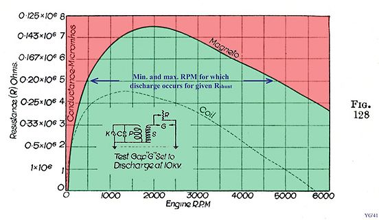
Diagramm der Entladungsbereiche von Magneto und Coil
0.25x10^6 4 0.33x10^6 3 0.5x10^6 2 1x10^6 1 0 Resistance (R) Ohms Conductance-Micromhos Magneto Min. and max. RPM for which discharge occurs for given Rshunt Coil K, C, S, P, R, G Test "Gap" Set to Discharge at 10KV. Engine R.P.M FIG. 128
in „Drehzahlmesser Impuls“ · Fahrzeugelektronik · · Diagramme
-
PDF
ADV7175A.pdf
20 A 1.112 1.235 1.359 V REF VREFOUT POWER REQUIREMENTS 7 VAA 4.75 5.0 5.25 V Normal Power Mode I (max) 8 150 155 mA DAC 8 DAC 9min) 20 mA CCT 100 150 mA Low Power Mode I (max) 8 80 mA DAC 8 DAC (min) 15 mA CCT 9 100 150 mA Power Supply Rejection Ratio COMP = 0.1 F 0.01 0.5 %/% NOTES 1The max/min specifications
-
PDF
ADT7420.pdf
7 of 24 ADT7420 Data Sheet TYPICAL PERFORMANCE CHARACTERISTICS 30 1.00 0.75 25 ) C 0.50 ) ( A 20 R MAX ACCURAC YLIMITS ( R 0.25 D R ID E N E 0 W 15 U O T T R–0.25 U E S 10 5.5V P MAX ACCURAC Y LIMITS E–0.50 5.0V T 5 4.5V –0.75 3.6V 3.3V 3.0V 2.7V 7 0 2 –1.00 - –100 –50 0 50 100 150 200 - –60 –40 –20
in „STM32F4 mit I2C-Sensor“ · Mikrocontroller und Digitale Elektronik ·
-
PDF
S1D13504_MF1072-04.pdf
Panel Power On / Reset Timing Table 7-22 LCD Panel Power On / Reset Timing Symbol Parameter Min. Typ. Max. Units TRESET# RESET# pulse time 100 us LCD Enable bit high to FPLINE, FPSHIFT, FPDAT[15:0], DRDY active TFPFRAME 1 + 6TPCLK ns 2 FPLINE, FPSHIFT, FPDAT[15:0], DRDY active to LCDPWR, on and 128 Frames
in „[V] Displaycontroller Epson SED1354 (800*600)“ · Markt ·
-
Datei
datei-dmesg.txt
to kernel taint [ 0.004901] mce: CPU supports 5 MCE banks [ 0.004938] Last level iTLB entries: 4KB 128, 2MB 0, 4MB 2 [ 0.004938] Last level dTLB entries: 4KB 128, 2MB 0, 4MB 8 [ 0.004938] tlb_flushall_shift: 6 [ 0.023469] Freeing SMP alternatives memory: 32K (c1aa6000 - c1aae000) [ 0.026020] ACPI: Core
in „Limux:: Netzwerk und WLAN futsch.“ · PC Hard- und Software ·
-
Datei
mmc_stm32f1.c
xchg_spi(0xFF); /* Diacard following one byte when CMD12 */ n = 10; /* Wait for response (10 bytes max) */ do { res = xchg_spi(0xFF); } while ((res & 0x80) && --n); return res; /* Return received response */ } /*-------------------------------------------------------------------------- Public Functions
in „STM32F103: Problem mit ChanFat und SD karte“ · Mikrocontroller und Digitale Elektronik ·
-
PDF
MP650_datasheet.pdf
0x17FF_FFFF 320 ~ 384MB Reserved 0x1000_0000 ~ 0x13FF_FFFF 256 ~ 320MB Peripheral 0x0800_0000 ~ 0x0FFF_FFFF 128 ~ 256MB Register File 0x0000_0000 ~ 0x07FF_FFFF 0 ~ 128MB DRAM The physical space 0x1c00_0000 to 0x1fff_ffff is mapped to either external Serial NOR Flash or internal boot ROM depends on the boot-up
in „Handydummy (Attrappe)mit richtigem Display 10Zoll - u.a.Motorola Xoom“ · Mikrocontroller und Digitale Elektronik ·
-
PDF
MAX712-MAX713.pdf
EVALUATION KIT AVAILABLE MAX712/MAX713 NiCd/NiMH Battery Fast-Charge Controllers General Description Features The MAX712/MAX713 fast-charge Nickel Metal Hydride ♦ Fast-Charge NiMH or NiCd Batteries (NiMH) and Nickel Cadmium (NiCd
in „Kleine Nimh ladeschaltung“ · Mikrocontroller und Digitale Elektronik ·
-
PDF
AudioCodec-WM8731_8731L.pdf
OPERATING CONDITIONS – WM8731L PARAMETER SYMBOL TEST MIN TYP MAX UNIT CONDITIONS Digital supply range (Core) DCVDD 1.42 1.5 3.6 V Digital supply range (Buffer) DBVDD 1.8 3.6 V Analogue supply range AVDD, HPVDD 1.8 3.6 V Ground DGND,AGND,HPGND 0 V PD Rev 4.0 February
in „Elektret-Mikrofon-Verstärker-->Line-In mit assymmetrischer Vers.Sp.“ · Mikrocontroller und Digitale Elektronik ·
-
Datei
TB-boot-log.txt
VIPT aliasing instructie [ 0.000000] Machine model: rockchip,rk3288-miniarm [ 0.000000] cma: Reserved 128 MiB at 0x78000000 [ 0.000000] Memory policy: Data cache writealloc [ 0.000000] PERCPU: Embedded 13 pages/cpu @eef8d000 s24216 r8192 d20840 u5328 [ 0.000000] Built 1 zonelists in Zone order, mobility
in „Asus Tinkerboard startet nicht“ · Mikrocontroller und Digitale Elektronik ·
-
PDF
ARM_Procedure_Call_Standard_for_the_ARM_Architecture_V2.1.pdf
__simd128_int64_t VLD1.64 {Qn}, [Rn] 2 signed double-word uint8x16_t struct __simd128_uint8_t 16 unsigned byte VLD1.8 {Qn}, [Rn] uint16x8_t struct __simd128_uint16_t 8 unsigned half-word VLD1.16 {Qn}, [Rn] uint32x4_t struct __simd128_uint32_t 4 unsigned word VLD1.32 {Qn}, [Rn] uint64x2_t struct __simd128_uint64_t 2 unsigned double- VLD1.64 {Qn}, [Rn] word float32x4_t struct __simd128_float32_t 4 single-precision floatLD1.32 {Qn}
in „C und C++ kompatibilität“ · Mikrocontroller und Digitale Elektronik ·
-
Datei
lcdconpar.asm
zweite Hälfte der Daten behalten or temp2, temp st X+,temp2 cpi XAdresseLow, 160 ;Spalten Adresse > Max ? brne normal clr XAdresseLow ;Spalten Adresse = 0 inc ZeileL ;Zeilen Adresse ++ cpi ZeileL, 240+ZStart ;Zeilen Adresse > Max ? brne normal ldi ZeileL, ZStart ;Zeile = Beginn XRAM sbr Flags, (1<<ZeileH
in „LCD Controller für 640x480 LCD mit mega8515“ · Projekte & Code ·
-
Datei
lcdconpar.asm
zweite Hälfte der Daten behalten or temp2, temp st X+,temp2 cpi XAdresseLow, XMax ;Spalten Adresse > Max ? brlo normal clr XAdresseLow ;Spalten Adresse = 0 inc ZeileL cpi ZeileL, YMax ;Zeilen Adresse > Max ? brlo normal ldi ZeileL, YMin ;Zeile = Beginn XRAM cbr Flags, (1<<ZeileH) ;MSB Spalten Adresse =
in „LCD Controller für 640x480 LCD mit mega8515“ · Projekte & Code ·
-
Datei
lcdconser.asm
zweite Hälfte der Daten behalten or temp2, temp st X+,temp2 cpi XAdresseLow, XMax ;Spalten Adresse > Max ? brlo normal clr XAdresseLow ;Spalten Adresse = 0 inc ZeileL cpi ZeileL, YMax ;Zeilen Adresse > Max ? brlo normal ldi ZeileL, YMin ;Zeile = Beginn XRAM cbr Flags, (1<<ZeileH) ;MSB Spalten Adresse =
in „LCD Controller für 640x480 LCD mit mega8515“ · Projekte & Code ·
-
Datei
lcdconser_.asm
zweite Hälfte der Daten behalten or temp2, temp st X+,temp2 cpi XAdresseLow, XMax ;Spalten Adresse > Max ? brlo normal clr XAdresseLow ;Spalten Adresse = 0 inc ZeileL cpi ZeileL, YMax ;Zeilen Adresse > Max ? brlo normal ldi ZeileL, YMin ;Zeile = Beginn XRAM cbr Flags, (1<<ZeileH) ;MSB Spalten Adresse =
in „LCD Controller für 640x480 LCD mit mega8515“ · Projekte & Code ·
-
Datei
lcdconser640x480.txt
zweite Hälfte der Daten behalten or temp2, temp st X+,temp2 cpi XAdresseLow, XMax ;Spalten Adresse > Max ? brlo normal clr XAdresseLow ;Spalten Adresse = 0 inc ZeileL cpi ZeileL, YMax ;Zeilen Adresse > Max ? brlo normal ldi ZeileL, YMin ;Zeile = Beginn XRAM cbr Flags, (1<<ZeileH) ;MSB Spalten Adresse =
in „LCD Controller für 640x480 LCD mit mega8515“ · Projekte & Code ·
-
PDF
ATmega8.pdf
------------------ 2 ⋅ N ⋅ (1 + OCRn) The N variable represents the prescale factor (1, 8, 32, 64, 128, 256, or 1024). As for the Normal mode of operation, the TOV2 Flag is set in the same timer clock cycle that the counter counts from MAX to 0x00. 109 2486Z–AVR–02/11 Fast PWM Mode The fast Pulse Width
in „Mikrocontroller und 15'' TFT LCD“ · Mikrocontroller und Digitale Elektronik ·
-
PDF
Siemens_B1023_Norma_MP14.pdf
Gleichspannung stellen. Frequenz bereich : 10 kHz bis 800 MHz bei Eingangs spannung 0,1 ...25 V AC Max. zulässige HF-Spannung : 25 V AC Max. zuläs sige : 500 V Gleichspannung Max. Ausgangs spannung :lVDC Eingangsimpedanz 100 kOhm // 2 pF bei 1 MHz und 1 V Fehlergrenzen : bezogen auf den Frequenzbereich
-
PDF
b_1023.pdf
Gleichspannung stellen. Frequenz bereich : 10 kHz bis 800 MHz bei Eingangs spannung 0,1 ...25 V AC Max. zulässige HF-Spannung : 25 V AC Max. zuläs sige : 500 V Gleichspannung Max. Ausgangs spannung :lVDC Eingangsimpedanz 100 kOhm // 2 pF bei 1 MHz und 1 V Fehlergrenzen : bezogen auf den Frequenzbereich
in „Hilfe bei Reparatur Siemens Multimeter“ · Analoge Elektronik und Schaltungstechnik ·
-
PDF
Samsung_64MB_K4M51323PC_1_8V.pdf
one time during 20ns mA in non power-down mode CKE ≥ VIH(min), CLK ≤ IL(max), CC= ∞ ICC2NS Input signals are stable 1 Active Standby Current CC3 P CKE ≤ VIL(max), CC = 10ns 6 mA in power-down mode ICC3PS CKE & CLK ≤ V I(max), CC = ∞ 3 CKE ≥ VIH(min), CS ≥ IH(min),CC = 10ns
in „PHILIPS VP5500 VoIP Telefon bei Pollin“ · Mikrocontroller und Digitale Elektronik ·
-
PDF
DS4E-M-DC1.5V-Panasonic.pdf
Type of relay (DS1-S type) (Other types) Max. switching power 60 W, 125 VA Initial Between open contacts 500 Vrms 1,000 Vrms breakdown Max. switching voltage 220 V DC, 250 V AC voltage*2 Between contacts sets — 1,000 Vrms Rating Max. switching
in „"Merkwürdiges" Relais.“ · Analoge Elektronik und Schaltungstechnik ·
-
PDF
ads830.pdf
max 5.9 12 ns ADS830 4 SBAS086A TYPICAL CHARACTERISTICS At T = full specified temperature range, single-ended input range = 1.5V to 3.5V, sampling rate = 60MHz, and external reference, unless otherwise
in „ads830 ad wandler“ · Mikrocontroller und Digitale Elektronik ·
-
PDF
ads831.pdf
Clock Cycles t2 Data Out N–4 N–3 N–2 N–1 N N+1 N+2 N+3 Data Invalid t 1 SYMBOL DESCRIPTION MIN TYP MAX UNITS CONV Convert Clock Period 12.5 100µs ns L Clock Pulse Low 5.8 6.25 ns t Clock Pulse High 5.8 6.25 ns H D Aperture Delay 3 ns 1 Data Hold Time, L = 0pF 3.9 ns t New Data Delay Time, C = 15pF max
-
Datei
config.h
this feature will be disabled and the tester runs * until it's powered off manually. */ #define CYCLE_MAX 5 /* * Automatic power-off when no button is pressed for a while (in s). * - applies to auto-hold mode only * - uncomment to enable, also adjust timeout (in s) */ //#define POWER_OFF_TIMEOUT 60 /* *
in „ComponentTester-1.42m problem“ · Mikrocontroller und Digitale Elektronik ·
-
PDF
FXOS8700CQ.pdf
. CMP_Z_LSB (0x3E) register cmp_z[7:0] FXOS8700CQ Sensors Freescale Semiconductor, Inc. 73 10.14.4 MAX_X_MSB (0x45), MAX_X_LSB (0x46), MAX_Y_MSB (0x47), MAX_Y_LSB (0x48), MAX_Z_MSB (0x49), MAX_Z_LSB (0x4A) registers The magnetometer MAX_X/Y/Z registers are 16-bit 2's complement format with a resolution
in „Beschleunigungssensor auslesen“ · Mikrocontroller und Digitale Elektronik ·
-
PDF
S1D15714_Technical_Manual__E_.pdf
value Unit Applicable Min. Typ. Max. pin Sleep state IDDS1 — — 0.3 5 µA — 48 EPSON Rev. 1.0 S1D15714 Series [Reference Data 1] • Dynamic current consumption during LCD display when the internal power supply is used. V 3 = 14V *13 150
in „Nokia LCD 3510“ · Mikrocontroller und Digitale Elektronik ·
-
PDF
CANopen_Referenzhandbuch_V2.5.pdf
HM-Modus) können aus der folgenden Tabelle entnommen werden. Motortyp 1,8° 0.9° Polpaare 50 100 (0x2006) Max. UPM 4800 2400 Schrittmodus Feed Feed Max. Max. (0x6092 sub1) (0x6092 sub1) Profile Accel. (Schritte pro (Schritte pro Velocity (0x6083, Umdrehung) Umdrehung) (0x6081) 0x6084) Vollschritt 200 400 16000
in „TIA Nanotec Schrittmotoren über CANopen einbinden“ · Analoge Elektronik und Schaltungstechnik ·
-
PDF
Dsht-ST20f.pdf
Temperature in °C Spread of the Temperature FaTtor k Streuung des TemperaturfaktTrs k TA( C ) Min. Typ. Max. T A C ) Min. Typ. Max. -50 0.506 0.518 0.530 50 1.204 1.209 1.215 -40 0.559 0.570 0.581 60 1.291 1.300 1.308 -30 0.615 0.625 0.635 70 1.383 1.394 1.405 -20 0.676 0.685 0.694 80 1.478 1.492 1.506 -10
in „Temperatursensor ST-20M (KTY19-6M) Doppelt abgeifen - Simple Messschaltung?“ · Mikrocontroller und Digitale Elektronik ·
-
 Bild
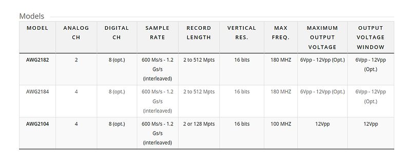
Tabelle mit technischen Spezifikationen von AWG Modellen
Models MODEL ANALOG CH DIGITAL CH SAMPLE RATE RECORD LENGTH VERTICAL RES. MAX FREQ. MAXIMUM OUTPUT VOLTAGE OUTPUT VOLTAGE WINDOW AWG2182 2 8 (opt.) 600 Ms/s - 1.2 Gs/s (interleaved) 2 to 512 Mpts 16 bits 180 MHZ 6Vpp - 12Vpp (Opt.) 6Vpp - 12Vpp (Opt.) AWG2184 4 8 (opt.) 600 Ms
in „RISC/V-basierter Router von Shenzhen Xunlong, neue Renesas-MCU, große Politik und mehr“ · Mikrocontroller und Digitale Elektronik · · Screenshots