the grid is an open loop phase angle estimation using Zero Cross Detector (ZCD) as introduced in [45]. However, its performance is deteriorated under polluted grid conditions. The weak grid power quality issues leads to malfunction of the ZCD based controllers [45]. Therefore, Phase Locked Oscillator
lipo-akkus-mit-ausgang-micro-usb-loetpads-1000ma Vielleicht kannst du ja mit einer Spannungsquelle ein geladenes Akkupack am Bat-Eingang simulieren und mit dem Multimeter nachvollziehen, wie die LED-Ansteuerung funktioniert. Alles andere müsste dann fürs Laden sein. Mit etwas Zerstörungswillen einige Leiterbahnen vom USB
...maxibrief 1,45€ - ich würde aber dennoch empfehlen erstmal die *Ursache* zu finden, dafür muss es der PAM nicht tun! Vll tuts aber auch und es war nur ne Fehlbedienung (nach Wechsel der Akkus), dann kann man das mit
www.mikrocontroller.net/topic/375945#4261476 > Als Spannungswandler kommt ein LF 33 CV von ST zum Einsatz. Drop: 0,45V, die 3,9/4V vom 18650 würde ja den ESP killen. Beschaltet ist dieser nur mit zwei Kondensatoren, 0,1uF und 2,2uF laut Datenblatt. Wenn nun vom Li-Ion 3,9V am TP4056 Modul anliegen kommen nur 1,6V
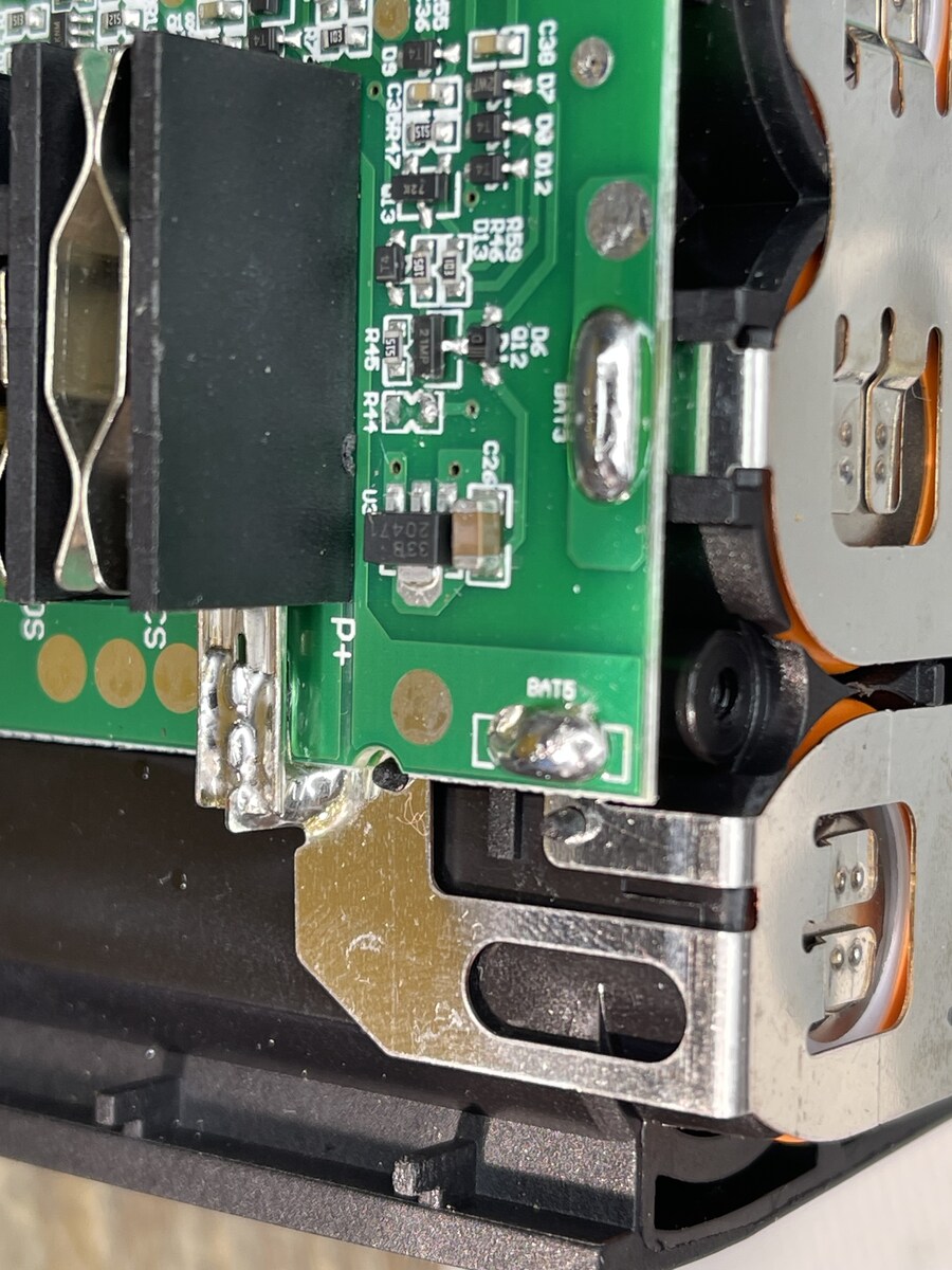
den Akku. Gut möglich, daß es die gerissen hat. Da sitzt ein MOSFET (bzw. zwei) zwischen "Out-" und "Bat-" und du kannst die beiden Pins *nicht* als beide GND und vertauschbar ansehen.
65678 P 1 R C1 1 CPOUT CHG 48 3 5 T 5 G C 2 47 1000 4 P - R4 3 NC_2 PACK 46 R43 Q15 T + A 4 CP4 PMS 45 200 GND R17 2 TP11 IRFS3306S - C2 5 CP3 NC 44 13 200 2 R CP2 GPOD R49 6 G - C R5 6 CP1 NC_4 43 R82 T 7 NC_3 VREG1 42 + A 8 DSG GND 41 Q16 3 R C3 9 BAT VREG2 40 IRFS3306S G C 10 39 200 P - R6 11 VC1 TOUT
3 Jahren BATs wechseln. Das Teil blinbt. Steht auch so drauf!
Chris D. schrieb im Beitrag #7548133: > Wir haben hier 2,45m. Da komme ich (1,85m) ohne größere Probleme und > Hilfsmittel an die Melder. Nun, ich hab' knapp 3.60m. Meine Nachbarn auch. Chris D. schrieb im Beitrag #7548133: > Aber: dafür gibt es heutzutage
a single 47-µF capacitor voltage. The supply voltage is further decou- 6/2000 Elektor Electronics 45 A U D IO and the line output. When a head- R2 T1 R5 330V phones plug is inserted into this 100Ω 6Ω8 U B R1 D4 R4 socket, it automatically disables the k k line outputs. The pentode section of 1 1 BUZ92
Active Supply (see Table 1A, T MIN to MAX , unless otherwise noted.) (Typical values aCC =t V 3.3V, BAT = 3.0V, and A = +25°C, unless otherwise noted.) (Notes 2, 3) PARAMETER SYMBOL CONDITIONS MIN TYP MAX UNITS Output Frequency fOUT VCC = 3.3V or BAT = 3.3V 32.768 kHz Frequency Stability vs. VCC = 3.3V
Jahre. Mir macht es spass dieses mit der DosBox x zu probieren. GW-Basic, Turbo-Pascal 3.02A , QB45 , QBx usw. Habe auch ein Deutschland-Ticket und bin 5x in der Woche unterwegs zur Nordsee, Ostsee oder anderen schönen Städten. Verfahre ca für 1000 Euro Bahn/Bus. Super...vielleicht kommt ihr
area 170 litres 130 litres 180 litres 180 litres contentat 50 mm PU insulation: Power consumption: 45W 35W 60W 60W Voltage 12Vg or24Vg Coolant quantity: 30 g 45 g 15g 65 g CO2equivalent: 0.043 t 0.064t 0.021 t 0.093t Globalwarming 1430 potential(GWP): Dimensions 375x350x25 255x210x90 450x270x340 365x140x270
used to measure the charge current as follows: I =V PROG×1200 (V PROG=1V) GND(Pin3): Ground Terminal BAT R PROG Vcc(Pin 4): Positive Input Supply Voltage V INis the power supply to the internal circuit. When VIN drops to within 30mv of the BAT pin voltage, TP4056 enters low power sleep mode, dropping BAT pin’s current to less than 2uA. BAT(Pin5): Battery Connection Pin. Connect the positive terminal of the battery to BAT pin. BAT pin draws less than 2uA current in chip disable mode or in sleep mode. BAT pin provides charge current to
Masse. Ich vermute den Fehler in diesem Mosfet bzw. in diesem Netzabschnitt. Dieser Mosfet liegt an AC_BAT_SYS und ich werde die zugehörige Trennstelle PJP8200 die Tage einmal öffnen
6,0V -> 0,8A 6,4V -> 1,0A Ich würde dann die Tage die 6,0V einspeisen und mal entlang des AC_BAT_SYS Pfades die Trennstellen wieder öffnen und schauen nach welcher geöffneten Trennstelle der Strom sinkt.
kann Theoretich das 6V Solarpannel direkt an den eingang des lademoduls hängen, dann den Akku an den Bat ausgang löten und an dem out ausgang die LED und dazu einen wiederstand Basteln der bei Dunkelheit öffnet. Wäre dieses vorhaben Realistischer ?
4 www.ti.com bq2085 SLUS541 – OCTOBER 2002 POR BEHAVIOR vs FREE-AIR TEMPERATURE V 2.50 150 – e t 2.45 145 o V V l 2.40 140 m h V V – e IT– hys g h 2.35 135 l t o u s n 2.30 130 s g r i t o 2.25 125 y e H i s a 2.20 120 y e V N – 2.15 115 T V 2.10 110 –20 –5 10 25 40 55 70 85 TA– Free-Air Temperature
in der Arduino DIE zugefügten Treiber vom STM zu installieren. Dafür als Admin die „install_drivers.bat“ und zum Teil auch die „install_STM_COM_drivers.bat“ ausführen um die Verknüpfung in Windows herzustellen… ebenfalls ohne Erfolg… Selbst hab ich bereits zwei funktionierende STM32-Boards hier liegen
werden da nur DFU Deskriptoren da sind. Mich würde ja mal interessieren was du an der Install_drivers,bat umgeschrieben hast.
bootstrap diode can be a low reactance (X L of capacitor comes to dominate, cost one such as IN4148 or BAT54. so that the ESL of input/output capacitor determines the input/output ripple voltage at 5V higher switching frequency. As a result of that, high frequency ceramic capacitor is strongly recommended
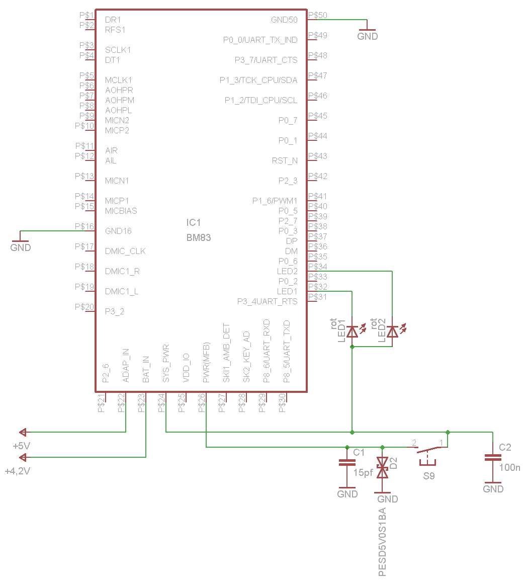
0402 0603 0402 0402 D12 PD Red GND CL2 GND GND P1 PI 4.7uH NOTE: 1). Using 3V3 LDO supply for BM83's BAT_IN, ensure there is no voltage drop when transient current is drawn from BM83 module. 2).Alternatively, make use of a LDO configured for 3V6 for BAT_IN, to B provide additional margin to encounter the
. Sollte es zu einem sehr starken Ausschlag kommen und der Pendelbereich überschritten werden (ca. 45°) "schlägt" das Pendel gegen ein Piezo Element um das Potential nicht vollständig zu verlieren. Das Wind- und Wasserrad wird, wenn nicht gewandert wird, im/beim Camp aufgebaut (Windrad am Wanderstock
Reichelt eine Diode gefunden mit 0.24V UF. https://www.reichelt.de/schottkydiode-30-vrrm-0-2-a-sot-23-bat-54a7f-dii-p219352.html?&trstct=pol_0&nbc=1 1.2.1 Ist noch nedriger realistisch? 1.2.2 Würde diese Diode für einen/diesen Gleichrichter funktionieren? 1.3 Da der Spannungsregler scheinbar mit
Absolute Maximum Ratings Over-operating free-air temperature range (unless otherwise noted) MIN MAX UNIT (BAT–VSS) bq76920 V Supply voltage (BAT–VC5x), (VC5x–VSS) bq76930 –0.3 36 V BAT (BAT–VC10x), (VC10x–VC5x), (VC5x–VSS) bq76940 (VCn–VSS) where n = 1..5 bq76920 (VCn–VSS) where n = 1..5, (VCn-VC5x) where n
avalanche er-ect required for wideband noise is not very prevalent due to The noise diode used is a BAT 31, which is the low breakdown voltages of the RF manutacturec by PhilipslMuilard in a micro transistors BFR 34a and BFR 96 of < 5V. Iis wave case type SO 86 (Figure 1). This case is mainly a tunnel
150wilha coilw idthl' _ '" 4n x 10 qx - xso:' x (ln - - 0.0) -s 30 mm, and using stranded wire 01 45 x 0.05 2 1.5 A mm oe . silk-covered enamelled wIre having a '" 3.45mH resistance 01R • 1.4 U. [IR... is neglected. and0Ris assumed to be A ", n x d x N xo. 2 0 /m _ 15.7 0 220 kU, .he lollowing will
(For Windows 95 and Windows 98 only) Specify the location of the license.dat file in your autoexec.bat file, which is usually located in your c: directory. To specify the licence.dat file, add the following line to your autoexec.bat file: set LM_LICENSE_FILE <pathname of license file> You must restart
Minimum) gelaufen, dazu wird der Empfänger wie eine Wünschelrute vor den Bauch gehalten und jeweils 45° nach rechts und links geschwenkt. Je näher der Fuchs kommt, in umso kürzeren Abständen schaltet der automatische Abschwächer herunter. Ein Blick aufs Display zeigt die geschätzte Restentfernung. Wenn
Voltage. VIN is the power supply to the internal circuit. 4 VIN When VIN drops to within 10mv of the BAT pin voltage, CN3058 enters low power sleep mode, dropping BAT pin’s current to less than 3uA. Battery Connection Pin. Connect the positive terminal of the battery to BAT pin. BAT pin draws less than
南京拓微集成电路有限公司 NanJing Top Power ASICCorp. Absolute Maximum Ratings ■ input supply voltage (VIN): 10V ■ BAT:-4.2V ~ 9V ■ BAT short duration: continuous ■ Maximum Junction Temperature: 145 ° C ■ Operating ambient temperature range: -40 C to 85 ℃ ■ Storage temperature range: -65 ℃ ~ 125 ℃ ■ Lead Temperature
avalanche er-ect required for wideband noise is not very prevalent due to The noise diode used is a BAT 31, which is the low breakdown voltages of the RF manutacturec by PhilipslMuilard in a micro transistors BFR 34a and BFR 96 of < 5V. Iis wave case type SO 86 (Figure 1). This case is mainly a tunnel
Gatespannung kompatibel mit 5V-Controllern. R, D, I, C PDF IRLML2502 0,17 max 20V, max 4,2A (cont.), 45 mOhm On-Widerstand SOT23 SMD-FET, extrem niedrige V_GS_th, bei niedrigem R_DS_on R, D PDF BS170 0,10 max 60V, bis 500mA, 5Ω On-Widerstand veraltete Technik, aber in bastelfreundlichem TO-92 Gehäuse R
0,22 UltraFast-Gleichrichterdiode, gestaffelte Sperrspannung, trr<50ns bzw 75ns 3A, 50..1000V R D BAT46 0,10 Kleinsignal-Schottky-Diode 150mA D,R D BAT54(A/C/S) 0,04 sehr schnelle Kleinsignal-(Doppel-)Schottky-Diode 200mA R,D,I D SB120..SB160 0,13 Schottky-Diode 1A 20-60V R,I D 1N5817..1N5819 0,15 Schottky-Diode
man die Platine ins Steckbrett stecken kann. Nach anfänglichen Schwierigkeiten wie: Mein F4 muß V_Bat verdrahtet haben und ohne einen V_Cap kann man den Chip zwar flashen, aber das Programm läuft nicht, weil der Core diesen Kondensator zum säubern der Betriebsspannung braucht. Zu meinem Erstaunen
. Aus genau demselben Grund habe ich mir ein kleines Alarmmodul entworfen. Rund um den Attiny25/45/85 - weil ich den persönlich kenne - eine simple Treiberstufe für den Piezo-Buzzer, mit 24Vdc versorgt aus einem boost-Konverter, zwei tilt-Schalter die bei +-15° Verkippung auslösen, betrieben mit 2x
EN 600626 Note Work week 45 Type code refers to individual datasheet Type code SOT-3xx MARKING DATE CODE XYZ 10 0 V Vishay Year 10 XYZ e.g. V0 H ... 2016 P ... 2022 W ... 2028 J ... 2017 R ... 2023 X ... 2029 K ... 2018 S ... 2024
150wilha coilw idthl' _ '" 4n x 10 qx - xso:' x (ln - - 0.0) -s 30 mm, and using stranded wire 01 45 x 0.05 2 1.5 A mm oe . silk-covered enamelled wIre having a '" 3.45mH resistance 01R • 1.4 U. [IR... is neglected. and0Ris assumed to be A ", n x d x N xo. 2 0 /m _ 15.7 0 220 kU, .he lollowing will
Supply Voltage V IN is the power supply to the internal circuit. When V INdrops to within 30mv of the BAT pin voltage, TP4056 enters low power sleep mode, dropping BAT pin’s current to less than 2uA. BAT(Pin5): Battery Connection Pin. Connect the positive terminal of the battery to BAT pin. BAT pin draws
> Eingangsschutz an den Busleitungen A und B gegen GND mit Dioden z.B. > PSM712, PEST1CAN oder BAT54 helfen. Man könnte auch noch zusätzlich mit > Dioden die Eingänge A und B auf +5V klemmen.
Weitere Möglichkeien zur Verbindung Signal-GND zu PE: * 1,5kOhm - sollte zu 30mA bei mehr als 45V führen, und damit ggf einen RCD auslösen. * RL seriell. * GND-Lift-Schalter

 Bild
Bild
 Bild
Bild
 Bild
Bild
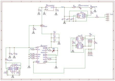
 Bild
Bild
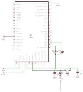
 Bild
Bild