
-
PDF
TI_ads5102_03.pdf
10 pF L at D0–D9, internal reference, T to T , typical data at 25°C (unless otherwise noted) (min) (max) internal reference voltages PARAMETER MIN TYP MAX UNIT VREFT Reference top voltage 1.30 1.34 1.39 V VREFB Reference bottom voltage 0.78 0.81 0.84 V VCML Common-mode voltage 0.85 1.05 1.15 V VBG Bandgap
in „Projekt Signal-Auswertung mit High-Speed-ADC“ · Mikrocontroller und Digitale Elektronik ·
-
 Bild
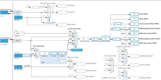
Blockschaltbild eines Mikrocontroller-Taktsystems
Input frequency, 32.768 KHz, LSE, 37 KHz, LSI RC, 37, HSE, / 2, RTC (KHz), 37, LSI, RTC (KHz), 37, Enable CSS, IWDG (KHz), 37, KHz, 2097, MSI RC, 8, MSI, HSE, PLLCLK, System Clock Mux, 32, 32 MHz max, FCLK (MHz), 32, HCLK (MHz), 16, / 1, HSI 16, 16, PLL, VCOInput, X 8, / 2, / PLLdiv, 48M Source Mux, 32, 32 MHz max, PCLK1, X 1, APB1 peripheral clocks (MHz), 32, APB1 timer clocks (MHz), 32, / 1, 32, PCLK2, 32, APB2 peripheral clocks (MHz), X 1, 32, APB2 timer clocks (MHz), 48 MHz, RC 48 MHz, / 2, USBCLK (MHz),
in „STM32L073RZ läuft auf HSE nur halb so schnell wie erwartet“ · Mikrocontroller und Digitale Elektronik · · Diagramme
-
PDF
Si4430-31-32.pdf
Sensitivity = –121 dBm Antenna diversity and TR switch control Output power range +20 dBm Max (Si4432) Configurable packet handler +13 dBm Max (Si4430/31) Preamble detector Low Power Consumption TX and RX 64 byte FIFOs Low battery detector 18.5 mA receive Temperature sensor
in „Leistungsanpassung bei bipolar Transistoren?“ · Analoge Elektronik und Schaltungstechnik ·
-
Datei
tools.c
0x0C #define MAX7219_NOP 0x00 #define MAX7219_DIGIT_0 0x01 #define MAX7219_DIGIT_1 0x02 #define MAX7219_DIGIT_2 0x03 #define MAX7219_DIGIT_3 0x04 #define MAX7219_DIGIT_4 0x05 #define MAX7219_DIGIT_5 0x06 #define MAX7219_DIGIT_6 0x07 #define MAX7219_DIGIT_7 0x08 /* Spielfeld 768 LEDs, pro LED ein Byte */ #define MIN_X 0 #define MAX_X 32 #define MIN_Y 0 #define MAX_Y 24 #define DEAD 0 #define ALIVE 1 /* Geschwindigkeit der Simulation */ #define
in „STM32F1xx: Wie GOL am "Leben" halten?“ · Mikrocontroller und Digitale Elektronik ·
-
PDF
XMEGA-A3BU_XPLAINED_Design_Documentation_rev2.PDF
2.54mm pinheader 21 L200 1 BLM15BB221SN1 Murata BLM15BB221SN1 SMD RF inductor 0402. Z=220Ohm (@100MHz), Max R(dc)=0.80Ohm, Max current=200mA 22 L300 1 BLM18HE152SN1 Murata BLM18HE152SN1 SMD RF inductor 0603. Z=1500Ohm (@100MHz), Max R(dc)=0.50Ohm, Max current=500mA 23 LABEL1 1 Label PCBA ACT Logimark AS 505462
in „LED toggeln mit ATxmega256A3BU“ · Mikrocontroller und Digitale Elektronik ·
-
PDF
tr_p_td71l.pdf
mmu n eC u re n t Tr a n s f o r me r Dimension PCB Mountable type (unt:mm/i nch) Dimension A(min) B(max) C(max) D(max) E(¡0 .3) F(¡0.3) G(¡0.5) H(¡0¾.3) I TD77V 6.8 25.0 11.0 23.5 15.1 19.1 3.0 9.1 0.268¡¨ 0.984¡¨ 0.433¡¨ 0.925¡¨ 0.594¡¨ 0.752¡¨ 0.118¡¨ 0.358¡¨ TD71V 11.2 28.7 17.0 26.9 15.1 19.1 3.0
in „Cadsoft Eagle“ · Platinen ·
-
PDF
SAM-V71Q-SAM-V71N-SAM-V71J_Datasheet.pdf
27-5. Calibration Circuitry Waveforms Monotonic 1 Hz Counter value 32.768 kHz +50 ppm Nominal 32.768 kHz Phase adjustment (~4 ms) 32.768 kHz -50 ppm -25 ppm Crystal frequency -50 ppm remains unadjusted Internal 1 Hz clock is adjusted Time Time -50 ppm correction period User
in „Atmel SAMV71 CAN FD“ · Mikrocontroller und Digitale Elektronik ·
-
Datei
logFile.txt
Modeline "800x600" 119.12 800 1728 1760 1840 600 1052 1058 1080 (**) RADEON(0): Default mode "1024x768": 119.1 MHz (scaled from 0.0 MHz), 64.7 kHz, 59.9 Hz (II) RADEON(0): Modeline "1024x768" 119.12 1024 1728 1760 1840 768 1052 1058 1080 (**) RADEON(0): Default mode "1152x864": 119.1 MHz (scaled from
-
Datei
GccApplication5.c
/* * GccApplication5.c * * Created: 20.10.2015 14:35:26 * Author: Max */ #include <stdlib.h> #include <stdio.h> #include <avr/io.h> #define F_CPU 1000000L #include <util/delay.h> void temp_mess(); void lcd_init(); void init_sequnez(); void schreibe(); int write_bit();
in „DS1820 reagiert garnicht, C Programm fehlerhaft? Sensor defekt?“ · Mikrocontroller und Digitale Elektronik ·
-
PDF
PIC_Applikationen.PDF
plan to use the serial port infrequently, consider powering the MAX chip through one of the PIC’s I/O pins. Your program could turn the MAX on shortly before it needed to send a serial message, and turn it back off afterward. This option is especially attractive for uses that require wringing the most life out of a set of batteries. A sample MAX232 that we tested drew 15 mA while driving two simulated serial-port loads. This is well within the PIC’s drive capabil- ity. A further test showed that the MAX232’s output voltages rose to their full
in „MATRIX-Tastatur“ · Mikrocontroller und Digitale Elektronik ·
-
PDF
LP133X7-A2.pdf
white mode. This TFT-LCD has a 13.3 inch diagonally measured active display area with XGA resolution (768 vertical by 1024 horizontal pixel array). Each pixel is divided into Red, Green and Blue sub-pixels or dots which are arranged in vertical stripes. Gray scale or the brightness of the sub-pixel color
in „13,3" LCD Display“ · Markt ·
-
PDF
MP650_datasheet.pdf
¾ Support digital input format : XRGB-888 , RGB-888, YCbCr 444/422 ¾ Output Resolution up to 1024x768 with SDRAM, and 1280x800 or 1366x768 with DDR ¾ Independent RGB gamma adjustment (32-step Piecewise-linear) ¾ Programmable ( Spatial or temporal ) dithering for RGB666 panels ¾ Embedded Digital TCON
in „Handydummy (Attrappe)mit richtigem Display 10Zoll - u.a.Motorola Xoom“ · Mikrocontroller und Digitale Elektronik ·
-
PDF
Si4330.pdf
Battery De2ector LBDCT — 250 — µs Conversion Time Microcontroller Clock MC Configurable to 30 MHz, 32.768K — 30M Hz Output Frequency 15 MHz, 10 MHz, 4 MHz, 3 MHz, 2 MHz, 1 MHz, or 32.768 kHz General Purpose ADC ADC ENB — 8 — bit Accuracy General Purpose ADC ADC RES — 4 — mV Resolution Temp Sensor & General
-
PDF
Si4734-35-C40.pdf
Characteristics (VDD = 2.7 to 5.5 IO= 1.85 to 3.6 A, T = –20 to 85 °C) Parameter Symbol Test Condition Min Typ Max Unit Reference Clock RCLK Supported Frequencies 1 31.130 32.768 40,000 kHz 2 RCLK Frequency Tolerance –100 — 100 ppm REFCLK_PRESCALE 1 — 4095 REFCLK 31.130 32.768 34.406 kHz Crystal Oscillator Crystal
in „[V] LCD Display, xMega128 mit USB, AM/FM Radio Empfänger“ · Markt ·
-
PDF
ND-LA.MV9.P-2.pdf
/.TRP MPEG-2,H. 264 AC3 1920x1080@30fbs Movie .MKV/M MPEG-4,H.264 Max Data Rate: 20 Mbps OV .MPG MPEG-1, MPEG-2 Max Resolution: .DAT MPEG-1 MP2 352x288 Max Data Rate: 20 Mbps Max Resolution: 720x .VOB MPEG-2 576 Max Data Rate: 20 Mbps Max Resolution And .RM/ VS, RV9,
in „Display CLAA154WB05AN an Pollinboard PI-MDV6822“ · Mikrocontroller und Digitale Elektronik ·
-
PDF
STM32F107.pdf
Table 9. Table 21. Low-speed external user clock characteristics Symbol Parameter Conditions Min Typ Max Unit f User External clock source 32.768 1000 kHz LSE_ext frequency(1) OSC32_IN input pin high level V LSEH voltage 0.7VDD VDD V OSC32_IN input pin low level V LSEL VSS 0.3VDD voltage tw(LSE) OSC32_
in „STM32-comStick USB-Bootloader“ · Mikrocontroller und Digitale Elektronik ·
-
PDF
RFM22B.pdf
and TR Sensitivity = –121 dBm switch control Output power range Configurable packet handler +20 dBm Max (RFM22B) Preamble detector +13 dBm Max (RFM23B) TX and RX 64 byte FIFOs Low Power Consumption Low battery detector 18.5 mA receive Temperature sensor and 8-bit 30 mA @ +13 dBm transmit ADC –40 to +85
-
PDF
xMegaTeile.pdf
CPOL-EUG C5 VF 220/50 K-G Reichelt 1 25MHz CRYTALHC49U-V Q3 14-Us25,000MHZ CSD 1 32kHz CRYTALTC26V Q1 32,768 MS1V-6 Reichelt 1 DSUB9 F09HPS X2 52-091101 CSD 1 4u7 L-EUL3225M L5 LQH3C 4,7µ Reichelt 1 1u L-EUL3230M L6 LQH3C 1,0µ Reichelt 1 LEDCHIPLED_1206 LED5 26-1201040 CSD 1 USB PN61729 X1 1575 CSD 1 Wago2
-
PDF
xMegaTeile.pdf
TRJ0011 TRJ0011 U$1 450001 Pollin 1 220u CPOL-EUG C5 VF 220/50 K-G Reichelt 1 32kHz CRYTALTC26V Q1 32,768 MS1V-6 Reichelt 1 4u7 L-EUL3225M L5 LQH3C 4,7µ Reichelt 1 1u L-EUL3230M L6 LQH3C 1,0µ Reichelt 1 Wago2 W237-02P X3 AKL 057-02 Reichelt 1 33u L-EULPIS L1 L-PIS4728 33µ Reichelt 1 100u CPOL-EUD/7343-31R C7 SMD TAN.100/6,3 Reichelt 1 MAX3232 MAX232 IC4 MAX 3232 CSE Reichelt 2 220 R-EU_R0603 R16 CSD 2 150 R-EU_R0603 R23, R24 CSD 2 10n C-EUC0603 C17, C27 CSD 2 15p C-EUC0603 C21, C22 CSD 2 47k R-EU_R0603 R11, R13 CSD 2 100 R-EU_R0603 R12
-
PDF
xMegaTeile.pdf
CPOL-EUG C5 VF 220/50 K-G Reichelt 1 25MHz CRYTALHC49U-V Q3 14-Us25,000MHZ CSD 1 32kHz CRYTALTC26V Q1 32,768 MS1V-6 Reichelt 1 DSUB9 F09HPS X2 52-091101 CSD 1 4u7 L-EUL3225M L5 LQH3C 4,7µ Reichelt 1 1u L-EUL3230M L6 LQH3C 1,0µ Reichelt 1 LEDCHIPLED_1206 LED5 26-1201040 CSD 1 USB PN61729 X1 1575 CSD 1 Wago2
-
Datei
petclock.txt
Quartz im weißen Keramik-Flachgehäuse mit Fenster (Suggested XTAL Sources Statek CX-IV-32.768 ??) 9x Kohleschicht-R 5x Diode OA 202 PH OA202 1x Elko 47µF 6,3V 85°C 2x Folien-C 1x Keramik-C 15pF 1x Folien-Trimmer-C 1x blauer Taster (unter dem +-30 s.-Loch) Zum Minutenwechsel gedrückt stellt er die Uhr um max +-30 Sekunden auf xx:xx:00. 1x Schiebeschalter write < > read 1x Wahlstecker 1 aus 8 (für die Interrupt-Rate ??) steckt auf Pin5 (wenn man gleich zählt wie den dahinterliegenden 4020) und geht auf dessen
in „Rarität gefunden: Petclock, eine RTC für alle CBM-Computer mit Userport aus den guten alten 80ern“ · Mikrocontroller und Digitale Elektronik ·
-
PDF
SMD-QUARTZ-CRYSTAL-SMD03025-4.pdf
STABILITY ±8 ppm ~ ±50 ppm (see FREQUENCY STABILITY VS. TEMPERATURE table) SHUNT CAPACITANCE (C 0) 2 pF max. DRIVE LEVEL 100 μW typ. / 200 μW max. ( 500 μW available on request) AGING ±2 ppm per year standard (±10 ppm max. after 10 years available on request) >500 MΩ DC/100V ±10% INSULATION RESISTANCE STORAGE
in „Bauteilidentifikation: Quarz oder Oszillator?“ · Analoge Elektronik und Schaltungstechnik ·
-
Datei
pal_board.c
RC oscillator * * This function calibrates the internal RC oscillator, based * on the external 32.768 Hz crystal clock source. * * @return True if calibration is successful, false otherwise. */ bool pal_calibrate_rc_osc(void) { /* * Use the 32.768 kHz external crystal oscillator as reference clock source
-
PDF
AVR128DA28_32_48_64.pdf
accuracy • Internal PLL up to 48 MHz for high-frequency operation of Timer/Counter type D (PLL) • 32.768 kHz Ultra Low-Power internal oscillator (OSC32K) • 32.768 kHz external crystal oscillator (XOSC32K) • External clock input – Single-pin Unified Program and Debug Interface (UPDI) – Three sleep modes
in „AVR64EA28: PIT-Interrupt“ · Mikrocontroller und Digitale Elektronik ·
-
Datei
tools.c
0x0C #define MAX7219_NOP 0x00 #define MAX7219_DIGIT_0 0x01 #define MAX7219_DIGIT_1 0x02 #define MAX7219_DIGIT_2 0x03 #define MAX7219_DIGIT_3 0x04 #define MAX7219_DIGIT_4 0x05 #define MAX7219_DIGIT_5 0x06 #define MAX7219_DIGIT_6 0x07 #define MAX7219_DIGIT_7 0x08 /* Spielfeld 768 LEDs, pro LED ein Byte */ #define MIN_X 0 #define MAX_X 32 #define MIN_Y 0 #define MAX_Y 24 #define DEAD 0 #define ALIVE 1 /* Geschwindigkeit der Simulation */ #define
in „Matrix indizierbar machen?“ · Mikrocontroller und Digitale Elektronik ·
-
PDF
DS3231_DATASHEET.pdf
Extremely Accurate I C-Integrated 2 RTC/TCXO/Crystal 1 AC ELECTRICAL CHARACTERISTICS (CC = VCC(MIN)to VCC(MAX)or VBAT = VBAT(MIN)o VBAT(MAX), BAT > VCC, A = TMINto TMAX, unless otherwise noted.) (Note 1) 3 2 PARAMETER SYMBOL CONDITIONS MIN TYP MAX UNITS 3 Fast mode 100 400 S SCL Clock Frequency SCL Standard
in „RTC DS3231 Pull Up Widerstände berechnen“ · Mikrocontroller und Digitale Elektronik ·
-
PDF
DS3231_M_MZ_Mems.pdf
fewer • Two Time-of-Day Alarms than 31 days, including corrections for leap year. The • 1Hz and 32.768kHz Outputs clock operates in either the 24-hour or 12-hour format • Reset Output and Pushbutton Input with Debounce • Digital Temp Sensor with ±3°C Accuracy with an AM/PM indicator. Two programmable
in „(empfindlicher) GPS Modul gesucht“ · Mikrocontroller und Digitale Elektronik ·
-
PDF
Schaltplan.pdf
Revision A4 0.1 Date: 30.12.2011 Sheet of File: E:\Data\..\io.SCHDOC Drawn By: 1 2 3 4 1 2 3 4 ext.DC :max.280mA USB-DC:max.100mA +5V USB U2 1 5 VBAT A 4 USB-IN BAT 1 Li-Ion 3.7V A VCC-EXT DC-IN R3 2 R27 JP1 GND 2 GND CHG 3 1M N.A. /CHG 3 MAX1555EZK-T 2 D2 active-lowif charge current> 50mA 3.7V - 7V extern
in „STM32 und USB-Bulk Transfer“ · Mikrocontroller und Digitale Elektronik ·
-
PDF
VAR-6ULCustomBoard-Datasheet.pdf
• Battery. Do not forget to insert the coin cell battery into JBT1. 2.5.2 Wi-Fi module improved 32.768 KHz input. The On SoM Wi-Fi module needs 32.768 KHz signal to be supplied for proper operation. There two options for a correct operation of the Wi-Fi module. • Use OSC_32K_OUT signal of the SoM. This
in „[V] Variscite DART-6UL Development Kit inkl. 7" LCD NXP iMX6UL“ · Markt ·
-
PDF
CAN-Tester_HID-de.pdf
high-speed) für 5 und 12V Systeme Betriebsspannung durch USB =5V und =3,3V Stromaufnahme 26,5mA typ. , 30mA max. Ein/Ausgangssignale max. +18V, diff. 1,5Vmin. Arbeitsfrequenz 16MHz CAN-Datentransfer einstellbar 100kBit/s...1MBit/s USB-Datentransfer 12MBit/s (full speed) Temperaturbereich -40 ... +85°C CAN-Protokoll 2.0A und 2.0B CAN-Klemmspannung -8 … +18V max. CAN_H und CAN_L differentieller Pegel CAN-Bus-Länge typ. 100m bei 500kBit/s Terminator wählbar 120Ω PC-Anschluß USB - B CAN-Bus-Schnittstelle 9pol. Sub-D-Stecker PC-Betriebssystem Windows 98SE, Me,
in „Hardware für CAN-Versuche gesucht“ · Mikrocontroller und Digitale Elektronik ·
-
PDF
Dokumentation_MBHATM128-0206.pdf
Stromaufnahme (ohne Peripherie) ca. 40mA • Strombelastung pro Port (Sink/Source) 20mA • AD Wandlereingänge max. Eingangsspannung +5V DC • Kein Verpolungsschutz • Kein Überspannungsschutz • Separate Massefläche für die AD-Wandlereingänge (Blockkondensator 100nF zwischen AGND und AVCC) • Platine industriegefertigt
in „atmega128 modul“ · Markt ·
-
Datei
Tacho.txt
Clock Prescaler Change Enable CLKPR = (1<<CLKPS0); // set prescaler = 2, Inter RC 8Mhz / 2 = 4Mhz, max value for 1.8V types PCMSK0 |= (1<<PCINT2); // PCI 2 on, this is PB2, reed contact wheel EIMSK |= (1<<PCIE0); // Pin Change INT0 on ACSR |= (1<< ACD); // Turn off analog comparator for power reduction
in „Zeitmessung mit Timer2 asynchron“ · Mikrocontroller und Digitale Elektronik ·
-
Datei
0221-TS-_antwort_empfangen_512-Test.c
Flüssigkristallanzeige FKA LC7981 // Uhr DS32C35 // MSP430F1611 // ----------------- // | XIN|- 32,768kHz // | | // Taster rot--|RST (58) XOUT|- 32,768kHz // P5.7|LED rot // | P5.6|LED Grün // 8 Mhz X2IN- | P2.1|Taster // | P2.0|Taster // 8 MHz X2OUT- | P1.0..P1.7|Daten FKA // | | // | P3.0| SPI BL1
in „512 Byte-Sektor einer SD-Karte mit E32-868T drahtlos übertragen“ · Mikrocontroller und Digitale Elektronik ·
-
PDF
RV-3028-C7.pdf
minutes, seconds, UNIX. Timer, Alarm and External event input with Time Stamp function. Clock output: 32.768 kHz, 8192 Hz, 1024 Hz, 64 Hz, 32 Hz, 1 Hz. 43 bytes non-volatile user memory, 2 bytes user RAM. I2C-bus interface: 400 kHz. 100% Pb-free, RoHS-compliant. Automotive qualification according to AEC-Q200
in „STM32 LQFP löten“ · Mikrocontroller und Digitale Elektronik ·
-
PDF
RV-3028-C7.pdf
minutes, seconds, UNIX. Timer, Alarm and External event input with Time Stamp function. Clock output: 32.768 kHz, 8192 Hz, 1024 Hz, 64 Hz, 32 Hz, 1 Hz. 43 bytes non-volatile user memory, 2 bytes user RAM. I C-bus interface: 400 kHz. 100% Pb-free, RoHS-compliant. Automotive qualification according to AEC-Q200
-
PDF
TPS_Datasheet.pdf
Case (1.20) 3.20 (0.126) 1.60 (0.063)1.20 (0.047) max. 1.20 (0.040.80 (0.031) 1.10 (0.043) T 3528-12 B Case (1.20) 3.50 (0.138) 2.80 (0.110)1.20 (0.047) max. 2.20 (0.080.80 (0.031) 1.40 (0.055) 3.45 ±0.30 V 7361-38 – 7.30 (0.287) 6.10 (0.240) (0.136 ±0.012
in „Was für besondere Kondensatoren sind das??“ · Mikrocontroller und Digitale Elektronik ·
-
PDF
CY8C38xxx.pdf
100 µs max Doubler 12 MHz Input dependent 48 MHz Input dependent 1 µs max ILO 1 kHz -30%, +65% 100 kHz -20%, +30% 1000 µs max kHzECO 32 kHz Crystal dependent 32 kHz Crystal dependent 500 ms typ, max is crystal
in „Cypress ICE Cube“ · Mikrocontroller und Digitale Elektronik ·
-
PDF
Si4730-31-34-35-D60.pdf
Characteristics (VA= 2.7 to 5.5DV, V = 1.62 tA 3.6 V, T = –20 to 85 °C) Parameter Symbol Test Condition Min Typ Max Unit Reference Clock RCLK Supported Frequencies 31.130 32.768 40,000 kHz 2 RCLK Frequency Tolerance –100 — 100 ppm REFCLK_PRESCALE 1 — 4095 REFCLK 31.130 32.768 34.406 kHz Crystal Oscillator Crystal
in „LM2528-3.3 & SI4735 & Bluetooth anliegen“ · Mikrocontroller und Digitale Elektronik ·
-
PDF
edison-module_HG_331189.pdf
methodology 0.5(*)V DD Period Jitter Trigger Position RTC clock specification Table 7 shows the 32.768 kHz clock specifications to the SoC driven by PMIC. Table 7 RTC clock input specification Symbol Parameter Min Typ Max Unit Notes Frequency – 32.768 kHz Long term accuracy -100 0 +100 ppm Intel® Edison
in „Intel Edison Breakout Board“ · Mikrocontroller und Digitale Elektronik ·
-
PDF
RTC-4553.pdf
application manual. http://www.epsondevice.com Specifications (characteristics) Terminal connection Absolute Max. rating Item Symbol Condition Min. Max. Unit Supply voltage V DD VDD-GND ____ __ +6.0 Input voltage V IN SI,SCK,WR,0,C1 -0.3 ____ V DD+0.3 V #14 #8 Output voltage VOUT SOUT, POUT S to r e d a s b a
-
PDF
PS-MPU-3300-00.pdf
Temperature CLK_SEL=0 -15 to +10 % CLK_SEL=1,2,3 ±1 % PLL Settling Time CLK_SEL=1,2,3 1 10 ms EXTERNAL 32.768kHz CLOCK CLK_SEL=4 External Clock Frequency 32.768 kHz External Clock Allowable Jitter Cycle-to-cycle rms 1 to 2 µs Gyroscope Sample Rate, Fast DLPFCFG=0 8.192 kHz SAMPLERATEDIV = 0 Gyroscope Sample
in „SPI Kommunikation mit MPU3300“ · Mikrocontroller und Digitale Elektronik ·
-
PDF
rv-3032-c7.pdf
EVI 27 (CBh to EAh) 100th Sec. to Ye2D RESET ELECTRICAL CHARACTERISTICS Symbol Condition Min. Typ. Max Unit AT 25°C Supply voltage VDD Temp. comp. 1.2 5.5 V More detailed information can be found in the Application Manual. Supply voltage VDD I C-bus active 1.4 5.5 V Current consumption I C-bus inactive
in „18650 Zelle zu 5V“ · Analoge Elektronik und Schaltungstechnik ·
-
PDF
DS3231.pdf
Extremely Accurate I C-Integrated RTC/TCXO/Crystal AC Electrical Characteristics (VCC = VCC(MIN) to CC(MAX) or VBAT = VBAT(MIN)to BAT(MAX) , BAT > VCC , A = MIN to TMAX, unless otherwise noted.) (Note 2) PARAMETER SYMBOL CONDITIONS MIN TYP MAX UNITS Fast mode 100 400 SCL Clock Frequency fSCL kHz Standard
in „DS3231 vs PCF8573, hilfe gesucht !“ · Mikrocontroller und Digitale Elektronik ·
-
PDF
DS3231_S_SN_Crystal.pdf
Extremely Accurate I C-Integrated RTC/TCXO/Crystal AC Electrical Characteristics (VCC = VCC(MIN) to CC(MAX) or VBAT = VBAT(MIN)to BAT(MAX) , BAT > VCC , A = MIN to TMAX, unless otherwise noted.) (Note 2) PARAMETER SYMBOL CONDITIONS MIN TYP MAX UNITS Fast mode 100 400 SCL Clock Frequency fSCL kHz Standard
in „(empfindlicher) GPS Modul gesucht“ · Mikrocontroller und Digitale Elektronik ·
-
PDF
SARA-G3_DataSheet__UBX-13000993_.pdf
SIM pins Parameter Min Typical Max Unit Remarks Low-level input 0.37 V VSIM = 1.80 V 0.60 V VSIM = 2.85 V High-level input 1.22 3.30 V VSIM = 1.80 V 1.95 3.30 V VSIM = 2.85 V Low-level output 0.00 0.35 V VSIM = 1.80 V, Max value atOL
in „GSM-Modul (SIM908) nur analoge Ausgänge für Anruf?“ · HF, Funk und Felder ·
-
Datei
tcpip_bsd_config.h
case senerio. *****************************************************************************/ #define MAX_SOCKET 32 /***************************************************************************** * The number of ticks per second to generate an TCP tick. * Used by the TCP state machine * All other timings
in „TCP/IP Stack PIC32“ · Mikrocontroller und Digitale Elektronik ·
-
PDF
PDFresult.pdf
life and reliability of the device. 7. DC CHARACTERISTICS (VDDV SS = 3.0V, Fm = 3.58 MHz, Fs = 32.768 KHz,A= 25° C, LCD on, INTERNAL PUMP DISABLE; unless otherwise specified) PARAMETER SYM. CONDITIONS MIN. TYP. MAX. UNIT OP. Voltage (W742C811) V DD - 2.4 - 5.5 V Op. Voltage (W742E811) V DD - 2.4 - 4.8
in „Pocket Comm One µC“ · Mikrocontroller und Digitale Elektronik ·
