Drain-to-Source Voltage (V) Fig 1. Typical Output Characteristics Fig 2. Typical Output Characteristics 1000 2.0 e I = 40A n D ) t 1.8 VGS = 10V ( s t 100 e 1.6 e n r O C T = 175°C e ) 1.4 e J u e r 10 o l1.2 o - a - - o - i (1.0 i r r TJ= 25°C , , 1 n 0.8 ID ( VDS = 15V S 0.6 RD ≤60µs PULSE WIDTH 0.1 0.4 1 2 3 4
is simplified by the substitutions 1 T=K' cos > (2.1-15) -w = K' sin4> producing a familiar trigonometric form K' cos > sin wt+ K' sin > cos wt= K' sin (wt+ 4» (2.1-16) The angle, 4>,is evaluated as sin 4> -w/K' -wL (2.1-17) tan > = cos 4>= lI(K'T) R 36 FilterBasics Chap
operational. To assure a noise margin, the MOS-FET’s should have a minimum threshold voltage V of e.g. 0.4V and VDD1 must stay below this value. The isolation feature can also be applied if no level shifting is required, VDD1 and VDD2 may have the same value, e.g. both 3.3V or both 5V. 11 Philips Semiconductors
architecture is given, followed by a description of each component presented in the architectural model. 4.1 MODBUS COMPONENT ARCHITECTURE MODEL USER APPLICATION Communication Modbus ClientModbus Backend Application Interface Interface t Layer e m Modbus Client Modbus Server e l a t n n M & Co e r l TCP u
keine Bauteile beschädigt werden. Vielen Dank für eure Hilfe und Rückmeldungen! Viele Grüße Sam
Bay Nachname Ka Firma Angemeldet seit 04.10.2025 18:30 Beiträge 1 TO: Benutzername sam1 Vorname Sam Nachname Firma Angemeldet seit 04.10.2025 16:30 Beiträge 3
, ebenfalls eine Variante an. 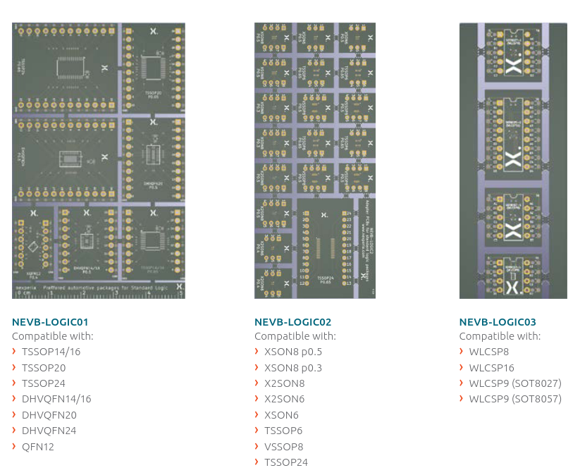 Bildquelle: Nexperia. ### SameSky: Knöpfe fortan auch aus Aluminium. Im Hause SameSky - bis vor einiger Zeit als CUI Devices bekannt - bietet man seit Jahr und Tag verschiedenste Knöpfe an, die auf die hauseigenen Potentiometer
sicherlich interessanten Details vertieft ... um dann unsanft auf dem Boden der Tatsachen aufzuschlagen: E36441A 3.042,00 € DM34460A 1.541,05 €
in Figure 7.37. As shown, the 12-bit formulation is approximately equivalent to a third-order (7°) eHiA OLA 9B6p0v2//1L CM) ZOLL 4828=0lL 6A 01 ISA ‘@g'lge- @o- zı BA 92/1 UL ZA ZEWVL 'e%e- 008 9A #1 EA 01 e'o- II4 Method Bits Bits Array Size Latency or Correct Max | Total Mpy | Add Order || Ave Min
frequency and phase response 0.6 45 0.5 5 V Vout = – .4657 mV - 5.0017*Vin Phase response reference ° e 0.4 Ta = 25°C d to amplifier gain of -1; 0° = 180° - a 0.3 - 0 0 e o 0.2 e n t 0.1 n dB o p o PHASE s u 0.0 s-5 -45 R - –0.1 R e t –0.2 a o –0.3 d h V –0.4 i-10 -90 P p - –0.5 m Ø –0.6 A –0.15 –0.10
reduced at relative humidity levels lower than 10%. 14Short term storage refers to temporary conditions e.g., during transport. 15For proper function of the ASC field-calibration algorithm with default parameters, SCD4x must 2e exposed to air with CO concentrations at 400 ppm on a weekly basis. 16Sensor
C706 C709 7 7 7 7 12.+16V_OLED 12.+16V_OLED A L709 4 2 1 4 13.D7 R256 R255 13.D7 T 4 0 1 6 L 2 14.D5 WF22 WF23 14.D5 C 7 C C 7 15.DGND RCD-N9 10K NC 15.DGND I C C E 16.D3 L L L 16.D3 I C723 C749 PF12 17.D6 DRA-N4 NC 10K 5 5
Teo D. schrieb im Beitrag #7933349: > War bei den Billigeimern von Pollin bisher nicht so. > Aber 4€ "riskieren"?! Nee, ich habe 04/2024 über Ali 4 Module für insgesamt 10,44€ gekauft. Gerd E. schrieb im Beitrag #7933623: > ICs wie MAS6180 und CME6005 werten ja rein die Amplitudenmodulation
Backup hat man natürlich GPS und Galileo und demnächst vielleicht noch DCF. Und wenn alles nicht geht, 4 lokale TCXOs. Ach Sch*e, es musste ja nur billig sein ;)
meinen Host µC jedes mal aufzuwecken. > Ein externes IC wird wohl weniger Strom verbrauchen, als ein SAM4E16E im > Sleep? Wer sagt das? Dieses kurze Aufwachen dauert wenige us und ist das Normalste in der Mikrocontrollerwelt. Siehe [[Sleep Mode]]. Dein SAM4E ist keine Linuxkiste.
: > > - Sleep Mode mit dem SAM4E > - RTC mit Millisekunden, wie die z.B. https://ww1.microchip.com/downloads/aemDocuments/documents/OTH/ProductDocuments/DataSheets/Atmel-11157-32-bit-Cortex-M4-Microcontroller-SAM4E16-SAM4E8_Datasheet.pdf
alternative development path that coexists together with the Zephyr RTOS-based nRF Connect SDK in the same environment and shares the same common tooling. Especially for developers currently still working with nRF5 SDK, we expect that the Bare Metal option is received with enthusiasm due to the API, architecture
added the ability to interface up-to 16 simultaneous ASIO channels and has eliminated the need to pay extra for more channels. APx500 Flex, APx516B, and APx517B now include the ability to connect to 16 ASIO channels at a time for the same
following exponential equation: Example: At tp = 62.5p.s and f= lkHz, IPEAK=100mA lV ( T =)1" ( 2 5 0 [-)~8E0/C(TA-25°C)1 IAVG = IP E A DF = (100mA)(1/16) =6.25mA 4. The maximum allowed operating conditions, not Example: for TA = 70°C, 1.79mcd/digit temperature derated, are now known. ~fthe operating (700c) = (4,17mcd)e [-.ois(70-WC)I = total for 16 ambient temperature is above 50°C, the operating segments conditions derived from Figure 1 must betemperature derated. OPTICAL AND CONTRAST Figure 2 derates the
0.5 sq. in. Additional PCB Cu 2.0 2.5 ) ) ( 1.8 ( c 1.6 e 2.0 a P s 1.4 x 1.5 s 1.2 M R t 1.0 d 1.0 T z 0.8 a 0.6 0.5 m o 0.4 0.0 N 20 40 60 80 100 120 140 0.2 Junction Temperature (°C) 0.0 -75 -50 -25 0 25 50 75 100 125 150 Specifications are subject to change
one pin is driven low, then returned to input with pull-up, * then the next pin is selected. * * Same as version 1, but lookup table loaded to RAM on startup. */ #include <avr/io.h> #include <avr/interrupt.h> #include <avr/sleep.h> #include <stdint.h> #ifndef F_CPU # define F_CPU 1E6 #endif #include
InputBiasCurrentvs.InputCommon-ModeVoltage Figure33.InputOffsetCurrentvs.InputCommon-ModeVoltage Rev. B | Page 16 of 33 Data Sheet ADA4807-1/ADA4807-2/ADA4807-4 300 10 25 V S ±5V ) 10 UNITS V 9 OIL BATH TEMPERATURE 24 µ ( (200 E 8 23 G G A T 7 22 L O 6 21 ) O100 V C V T 5 20 ( E S E S F 4 19 U F 0 O 3 18 T O T R D U 2 17 E R N M –100 I 1 16 E F I 0 15 T E G R I –1 14 U200 N P A –2 13 I H V = ±2.5V C –3 8 UNITS, SOLDERED TO PCB 12 –300 –4 11 4 –5.2 –3.9 –2.6 –1.3 0 1.3 2.6 3.9 5.2 1 0 100 200 300 400 500 600 - 1 6 INPUT
to form the resulting file name is the same as the number preceding the name of the interface in the drop down list box of OptiCall. Example Setups Page 15 of 26 O P E R A P N O T E ( 1 ) O N 2.4.2 If you have only one Audio interface board This
features and options: only combinations in the same row are possible. See coil specifications Preferred selections for best availability are shown in bold. Type Coil version A B C D 40.11 sensitive DC 2 - 4 0 0 0 40.11 sensitive DC 2 - 4 0 16 / 40.41
reconstruction based on network deep learning, and targeted denoising. Acquiring sharper images, faster + 7 a a 4 Powered by Conventional Deep Resolve Gain & Sharp artificial intelligence 0.9 x 0.9 x 4.0 mm³ 0.5 x 0.5 x 4.0 mm³ TA 5:16 min TA 3:48 min 8 Magnetic Resonance · MAGNETOM Free.Max Image courtesy of University
26 z 68 H 24 ( ) y H n ( 66 u 22 y q n r u e 20 q 64 d r M F n e 18 62 r G 60 16 -40 0 40 80 120 125 -40 0 40 80 120 125 Temperature (°C) Temperature (°C) Fig. 3 Frequency vs. Temperature Fig. 4 Green Mode Frequencyvs. Temperature 70 25 ) 68 H 23 ( ) y H 66 n ( u 21 y q n r u 64 e q d 19 r M F n 62 e 17 r G 60 15 11 12 14 16 18 20 22 24 25 11 12 14 16 18 20 22 24 25 Vcc (V) Vcc (V) Fig. 6 Green Mode Frequencyvs. Vcc Fig. 5 Frequency vs. Vcc 7 Leadtrend Technology Corporation www.leadtrend.com.tw
www.ti.com I C Examples 2 4.2.2 ADS1115 I C Example Read The ADS1115 has a 16-bit ADC and therefore puts out 16-bit data conversions. The controller device reads from the conversion register to get the ADC conversion data. The
A JUMPER PLUG MUST BE USED IN ITS PLACE. 17 2091702_H - BK150FUE-1 Installation and User's Manual 4 Electrical Diagrams for BK150FUE-1 Boxes 4.13 Smart Start™ NXT Distribution Box Overview ) LE NB , OS T S LU E R G DM B U L OU T A P ML G F E /P E G L (E W I ( SP E P D . EU T / S E CJ U I U A I, O A
= 15 mA 30 ns f Note: 5. Pulse test: pulse width ≤ 300 μs, duty cycle ≤ 2.0%. www.onsemi.com 3 2 N 4 4 Typical Performance Characteristics 0 1 / M ) ( M I E B G500 A0.4 T T VCE 5V L 4 E O β = 10 4 R400 V 0 U E0.3 1 C 125 °C T — D300 M S -0.2 125 °C N U200 R P P 25 °C T 25 °C N A E I100 L0.1 G P - 40
HCPL0500, HCPL0501, HCPL0531, HCPL0534 TYPICAL PERFORMANCE CURVES 1.2 1.2 1.0 1.0 T 0.8 T 0.8 C C D D Z E L 0.6 L 0.6 A A M M O 0.4 R 0.4 N N Normalized to: VO= 0.4 V Normalized to: IF= 16 mA F= 16 mA VCC= 5 V TA= 25_C VCC= 5 V 0.2 TA= 25_C 0.2 VO= 0.4 V 0.0 0.0 0.1 1 10 100 −60 −40 −20 0 20 40 60 80 100
applications, instead of having only into account the left and right channels, the block diagram of Fig. 4 has been modified and is pre- sented in Fig. 5. The n input channels are filtered by the HP blocks with the same f ch and then are routed to an adder. As in the stereo block diagram, the summation of all
over temperature protection) ● Input interface : 5V high active logic ● UL Recognized : UL1557 File E323585 INTERNAL CIRCUIT P1 (1) R (36) S (35) T (34) N1 (2) NC (3) VNC (4) NC (33) NC (5) V (6) P1 V UFB(7) HVIC V UFS(8) P (32) V VFB(9) VVFS(10) V WFB(11) U (31) V WFS(12) U P13) VP(14) V (30) W P15)
man 2400 bps nicht erreichen. Mit folgenden Settings kommst du in die Nähe: - BW=31.25 kHz, SF6, CR4/5 => 2343 bps - BW=62.5 kHz, SF7, CR4/6 => 2278 bps - BW=41.67 kHz, SF6, CR4/7 => 2232 bps - BW=125 kHz, SF8, CR4/7 => 2232 bps - BW=250 kHz, SF9, CR4/7 => 2511 bps - BW=31.25 kHz, SF5, CR4/8 =
Nano 33 BLE and Arduino Portenta H7 megaAVR - Arduino Uno WiFi Rev.2 and Nano Every SAM - Arduino Due SAMD - Arduino Zero, MKR boards, M0 Pro etc. Renesas - Arduino Uno R4 Adafruit SAMD - Adafruit Feather M0 and M4 boards (Feather, Metro, Gemma, Trinket
Foreground R/G/B/Intensity Color. If the value is set as 0000b, then there will be no foreground, i.e. transparent. when Character Data = C0h~FFh, these 4 bits act as a pointer to one of 16 the Character 2BP color sets 2.10.3.3Row Attribute (Default=XXXXXXXXb) 资料收藏: Table 2-4 Row Attribute 7 6 HTTP:/
TSSOP24 D A L terminal 1 A A A V S CS index area 2 2 2 2 2 1 LED0 1 18 RESET LED1 2 17 LED15 LED2 3 16 LED14 PCA9532BS LED3 4 15 LED13 LED4 5 14 LED12 LED5 6 13 LED11 7 8 9 1 1 1 6 7 S 8 9 1 E DE V E DE D 002aae520 L L L L L Transparent top view Fig 4. Pin configuration for HVQFN24 PCA9532 All information
180 V , DC BLOCKING VOLTAGE (V) T , LEAD TEMPERATURE (°C) R L Figure 3. Typical Capacitance Figure 4. Maximum Current Ratings http://onsemi.com 2 MR2535L 1 45 ) 40 L E C ) Maximum M I N /35 R A T ° Typical E M I (30 T R E A Single to heatsink T N R L25 E (0.1 L Maximum S C M T20 N N R N R T H I15 Typical
18 8 Vp Vo 1 6 +5V 3 C 3 C 3 C 7 Vcc WR RD E ME IOE 15 2 3 2 7 12 BRQ A1 >> A1 /RTCCS >> CSO ALE F Vs U1 NC R72 40106 R52 7 GND F F F 52 16 8 17 5 2 1 F 5 3 U20 11 PUMP COUNTS VOL CNT P 6 P 4 P 2 51 NC A2 17 >> A2 /RD>> 10 RD VDD 16 1 C C U 0 4
