1: I C Bus Start/Stop Bits Timing Waveforms. 2 TABLE 1-1: I C BUS START/STOP BITS REQUIREMENTS I C AC Characteristics Standard Operating Conditions (unless otherwise specified) Operating Temperature –40C T +125C (Extended) Operating Voltage DD range is described in AC/DC characteristics Param.
Operation). Before executing the next instruction, be sure that BF is not “High”. Address Counter (AC) The address Counter (AC) stores DDRAM/CGRAM addresses, transferred from IR. After writing into (reading from) DDRAM/CGRAM, AC is automatically increased (decreased) by 1. When RS = “Low” and R/W = “High”, AC can be read through ports DB0 to DB6. Display Data RAM (DDRAM) DDRAM stores display data of maximum 80 8 bits (80 characters). DDRAM address is set in the address counter(AC) as a hexadecimal number
; Maksimovi▯ c, 2004). This small-signal AC model describes how small variations of the U1 and U2 sources and the α duty cycle will change the outputs iOut and u Out. Therefore, the linearized AC model (non-linear terms are ignored) is 6 Only
POLYFOAM B 506-7K-683B 1 3 SOFT BAG(830*480+80mm) 509-7K-349 1 4 USB CABLE(L=1500mm,CORE) 408-MC7K-145 1 AC POWER CORD(L=1900mm,3P UL/CSA/3P) 409-HDJ7100-054D 1 USA AC POWER CORD(L=1900mm,VDE TYPE) 409-HDJ7100-055D 1 Europe 5 AC CORD(L=2000mm,SP-305B/IS-14,PSE TYPE) 409-500C-219 1 Japan AC POWER CORD(L=1900mm
RMS Root mean square TRMS True root mean square (urspr. ein Marketingbegriff von Fluke) RMS AC Effektivwert AC-gekoppelt (nur Wechselanteil) 31 RMS DC Effektivwert DC-gekoppelt (Gleich- und Wechselanteil) Fazit: Elektronische Messgeräte mit TRMS-Wandler ermitteln aus unterschiedlichen Signalen
70 105 t Fall Time f 10 15 ns Turn-On Delay Time td(on) 55 83 Rise Time r VDD = 15 V, L = 0.67 180 270 Turn-Off Delay Time td(off) ID 22.5 A, GEN = 4.5 V, g = 1 55 83 t Fall Time f 12 18 Drain-Source Body Diode Characteristics Continuous Source-Drain Diode Current IS TC= 25 °C 120 a A Pulse Diode
Checktheantennaterminals,metaltrim,“metallized”knobs,screws, and all other exposed metal parts forAC leakage. Check leakage as described below. LEAKAGE TEST The AC leakage from any exposed metal part to earth ground and from all exposed metal parts to any exposed metal part having a return to chassis
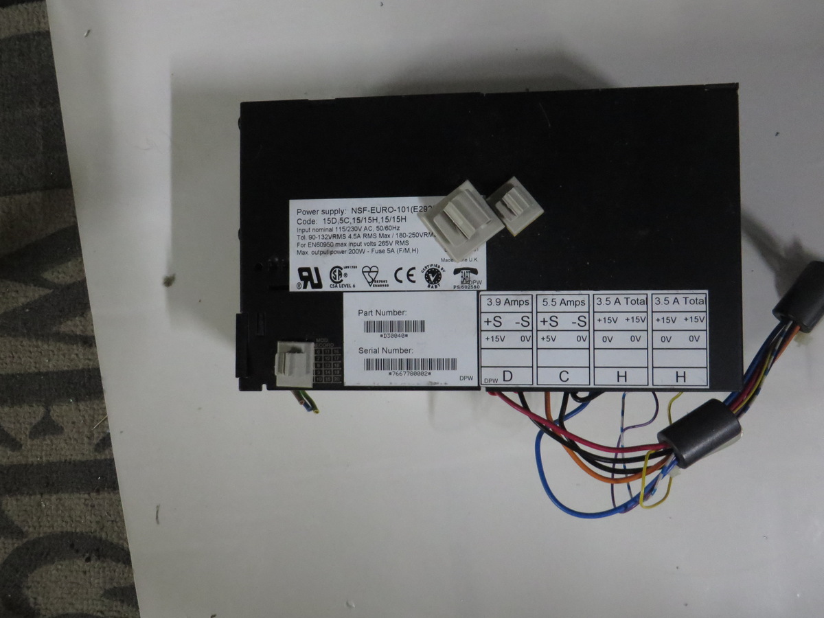
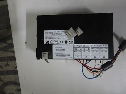
Power supply NSF-EURO-101(E2) Code: 15D,5C,15/15H,15/15H Input nominal 115/230V AC 50/60Hz T.S. (02)3865.6A Max Input 180-250V/A For EN60950 Max input volts 265V RMS Max output 200W - Fuse 5A (F/M/H) Made in U.K. CE Part Number: *230840* Serial Number: *766778082* 3.9 Amps +S -S +S
beschäftigen, um es evtl. aktualisieren zu können. Anbei 2 LTspice-Simulationen (Transient und AC Analysis). In der Datei Audacity_Impuls_kurz_32PCM.wav befindet sich ein digitalisierter Impuls. Die Parameter für PULSE sind die beste Näherung an diesen Impuls, die ich finden konnte. Ich möchte
schrieb im Beitrag #7780691: > 3. Bei n5, n6 und für den output waren die Phasenwerte von Octave um 180° > höher, als bei LTspice. 180° höhere Phasenwerte bedeutet eine Invertierung. Ohne jetzt im Detail nachgerechnet zu haben, hört sich das für mich nach einem Vorzeichenthema an. zu 5: Das Vorzeichen
die Ansteuerung mit PNP und nur 5V noch > nicht. > Ich dachte, dass ein VFD leuchtet, wenn zB. 5V AC Heizspannung und +20V > am Gitter und Segment gleichzeitig anliegen Es müssen ca. 3V (DC oder Effektivwert AC) an den Enden des Filaments anliegen, so daß selbiges ganz schwach dunkelrot glüht (
gleichrichten (z.B. 4x 1N4148) und eine Wicklung einsparen. [1] die Heizung braucht ca. 3V×60mA=180mW. Die Sekundärspannung ca. 21V×20mA=420mW. Zusammen also 600mW.
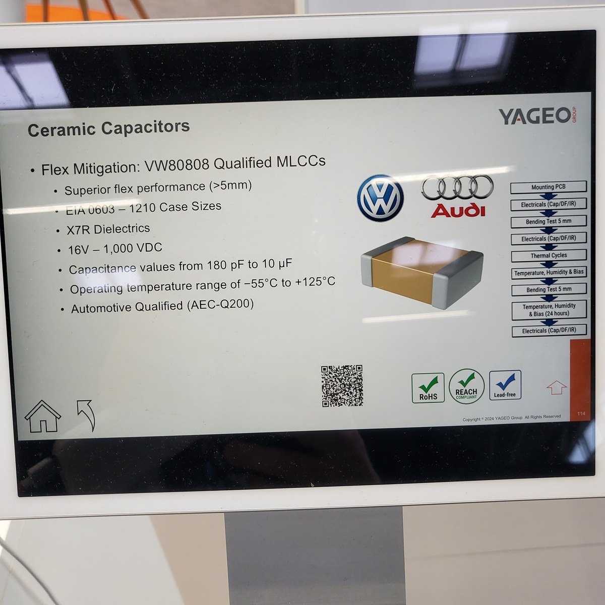
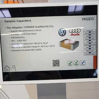
performance (>5mm)
EIA 0603 – 1210 Case Sizes
X7R Dielectrics
16V – 1,000 VDC
Capacitance values from 180 pF to 10 µF
Operating temperature range of -55°C to +125°C
Automotive Qualified (AEC-Q200)
YAGEO GROUP
Mounting PCB
Electricals (Cap/DF/IR)
Bending Test 5 mm
Electricals (Cap/DF/IR)
Thermal Cycles
Temperature
dem Foto des SNT sieht man sogar, dass der Layouter + und - vertauscht hat und deshalb die Pins um 180° "nach unten" gebogen werden mussten.
Serienbezeichnung? Gibt es irgendwo ein Nichicon Datenblatt? https://www.nichicon.co.jp/english/products/aec/page-alm_larg/ nichts was irgendwie DP heißt, scheint wirklich Antik zu sein.
Detection CNT (TEF) (LOD) Shift Constant-Current Register GS−Register 1PWM−Controlcale Driver OUT15 191 180 Delay x15 XERR 95C−Regis90r 6!Bit−Dot−Correction 191 LED−Open−Detection SOUT 1 Please be aware that an important notice concerning availability, standard warranty, and use in critical applications of
threshold). To force stereo, and later, Si4732 set to 100. To force mono, set to 0. The default is 60. 0x180A FM_BLEND_MULTIPATH_ Sets the stereo to mono 0x0FA0 Si4704/05-D50 and later, ATTACK_RATE attack rate for Multipath Si4706-D50, based blend. Smaller values Si4730/31/34/35-D60 provide slower attack and
+ 171 10101011 253 AB ADD A 2 INDEXED 5 Add Memory contents to the Accumulator , 172 10101100 254 AC CPX X 2 INDEXED 6 Compare the contents of Mem to the Index Reg - 173 10101101 255 AD JSR 2 INDEXED 8 Jump to Subroutine . 174 10101110 256 AE LDS S 2 INDEXED 6 Load the Stack Pointer 6800 Instruction
. 3, 4 63 24575-158 6 c 0 1 3, 4 84 24575-178 Maßtabelle Gehäusebreite a b c TE mm mm mm 28 249,32 180,32 202,72 42 320,44 251,44 273,84 63 427,12 358,12 380,52 84 533,80 464,80 487,20 ° 4x3 4 3° 02004080 Erdungssatz Hauptkatalog 쮿 Die Schutzleiterverbindungen entsprechen: DIN EN 50178/VDE 0160 DIN EN
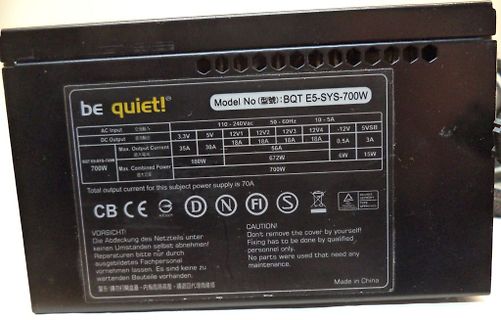
nehme. > Das Ding hat 700Watt und läuft den ganzen Arbeitstag also maximal 6kWh. Bei 6 kWh an 180 Tagen würdest du anders denken oder?
nehme. >> Das Ding hat 700Watt und läuft den ganzen Arbeitstag also maximal 6kWh. > > Bei 6 kWh an 180 Tagen würdest du anders denken oder? Überhaupt nicht wenn es sich immer um denselben Verbraucher handelt. Da ist doch die Leistungsaufnahme überschaubar bzw. die Arbeit berechenbar. Also 180 Tage
bieten Fachhändler. 36 Anschlussplan 10 1 8 2 x 0,75 mm² PM 5 2 4 x 0,75 mm² 6 OSMROT 3 O 3 x 1,5 mm² AC 230 V 4 x 0,75 mm² 3 3 2 x 0,75 mm² 2 x 0,5 mm² 9 7 2 x 0,75 mm² 10 8 1 5 PM 2 4 x 0,75 mm² RTNAR 6 MOSM 3 O 3 x 1,5 mm² AC 230 V 4 x 0,75 mm² 3 2 x 0,5 mm² 2 x 0,75 mm² 4 9 7 1,5 mm²–2,5 mm² 37 Verdrahtungsplan AC 230 V Sec. 24 V 24 W max. 0V 24 V 30 W max. E-Schloss # 3205V003 38 SOMMER Antriebs- und Funktechnik GmbH Hans-Böckler-Straße 27 73230 Kirchheim/Teck Germany +49 (0) 7021 8001-0 +49 (0) 7021 8001-100
Diodenmessbereich einen deutlich geringeren Spannungsabfall über dem Parallelkondensator als die anderen beiden (180mV statt 550mV), war schon verdächtig. Nach Tauschen des Shunts, Cu-Draht über die Leiterbahn und Tauschen des Elkos Wiederinbetriebnahmeversuch gemacht, Puff, keine Funktion. Neuen IRDAKO bestellt
Ruhezustand liegt da nichts an, gut. Wenn sich der Motor drehen soll zeigt mein DMM konstant 235V AC an. Das Relais, das die Platine ansteuert, würde ich also somit auch mal ausschließen. Alle anderen Stecker der Platine sind unbelegt (Acceleration Sensor, Pressure Sensor, D-Bus). Nun gibt es ein
of the internal memories are managed by Permission Control module. An internal memory can only be ac- cessed when it is allowed by Permission Control, then the internal memory can be available to the CPU. For more information about Permission Control, please refer to Chapter 14 Permission Control (PMS
only if • HVAC Systems the regulator is located far from the filter capacitor of the power supply. • AC Inventors • Test and Measurement Equipment LM7805 is also available in a higher accuracy and better performance version (LM340A). Refer to • Brushed and Brushless DC Motor Drivers LM340A specifications
Aus 25kV AC und 5kV AC kann man per travo 4kV DC machen, den Rest erledigen 4Q-Steller. VG
ist noch nicht möglich. Der Lokführer kann zwischen folgenden sechs Systemen wählen: 15 kV AC DB 15 kV AC SBB 25 kV AC NS 25 kV AC SNCF und SNCB 1,5 kV DC verstärkte Ausführung NS 3 kV DC verstärkte Ausführung SNCB Zusätzlich muss ein Wechsel der Zugsicherungssysteme
Düsen für Drucker von "Creality" ansieht, wie z.B. https://m.media-amazon.com/images/I/81Y7vojPeVL._AC_UF894,1000_QL80_.jpg dann ist offensichtlich, daß die eigentliche Heizung woanders sitzt.
gedruckt. Ich hab den mal unten in den Schraubstock eingespannt und dann oben mit der Zange um 180Grad einmal rum gedreht. Dabei ist das Teil am Stueck geblieben und ich kann das Teil jetzt mit den Haenden auch nicht auseinanderbrechen! Fuehlst sich beim verdrehen auch zaeh und fest an. Ich
at full load HOLD UP TIME (Typ.) 16ms/230VAC 12ms/115VAC at full load VOLTAGE RANGE 90 ~ 132VAC / 180 ~ 264VAC by switch 240 ~ 370VDC (switch on 230VAC) FREQUENCY RANGE 47 ~ 63Hz EFFICIENCY (Typ.) 79.5% 81.5% 83.5% 85% 86% 88% 88.5% 89% INPUT AC CURRENT (Typ.) 6.8A/115VAC 3.4A/230VAC INRUSH CURRENT
1200/18 E Absolute Maximum Ratings Symbol Conditions Values Unit Chip T(AV) Tc= 85 °C 1200 A sinus 180° Tc= 100 °C 840 A TSM Tj= 25 °C 30000 A 10 ms Tj= 125 °C 25500 A it T = 25 °C 4500000 A²s 10 ms j Tj= 125 °C 3251250 A²s Capsule Thyristor VRSM 1800 V V 1800 V RRM VDRM 1800 V (di/dcr Tj= 125 °C 125
of the internal memories are managed by Permission Control module. An internal memory can only be ac- cessed when it is allowed by Permission Control, then the internal memory can be available to the CPU. For more information about Permission Control, please refer to Chapter 14 Permission Control (PMS
Programmable Logic Device Family Data Sheet Figure 9. FLASHlogic AC Test Conditions VCC Power-supply transients can affect AC measurements. For accurate measurements, avoid simultaneous 165 transitions of multiple outputs. Do not perform threshold tests under AC Device
and SOIC-8 allowing the devices to act as both a rectifier and plastic packages. current source in AC applications. Connection Diagrams Figure 1. SOIC-8 Surface Mount Package Figure 2. SOIC-8 Alternative Pinout Surface Mount (LM334M; LM334M/NOPB; LM334MX; Package LM334MX/NOPB) (LM334SM; LM334SM/NOPB;
PHL(R), PW in PG3 PG1 PG2 *Includes capacitance of probes, wir- ing, and fixture parasitic. Note: AC test waveforms for PG1, TL/F/5998–5 PG2, and PG3 on next page. TL/F/5998–6 FIGURE 2. AC Test Circuit 5 Logic Diagrams ((/2 of Device Shown) (Continued) TL/F/5998–7 FIGURE 3. AC Test Waveforms TL/F/5998
Harald K. schrieb im Beitrag #7748062: > Drauf läuft die 180-Tage-Testversion des Windows Server 2022, ich kann > damit leben, die Kiste alle drei Jahre plattmachen zu müssen. Klingt nach stressiger 6-Tage-Woche. Einen Tag Arbeit, 6 Tage Freizeit.
zu können. Ich würde zu Thunderbolt 4 raten: https://m.media-amazon.com/images/I/71VbKVqzYkL._AC_SL1500_.jpg (prx) A. K. schrieb im Beitrag #7751536: > Flexibler wirds mit USB-C Thunderbolt ab Version 3. Aber auch teurer, > mindestens was das Dock angeht. 70 Ocken ist jetzt nicht zu teuer
dass ihre Chips nicht China in die Hände > fallen. https://www.ft.com/content/b76ef55b-21cd-498b-ac16-5660908bb8d2 Ich sag ja, Du bist wirklich lustig Völlig wirr in der Birne, aber lustig. :-)
168號 TSMC sitzt in Taiwan und Taiwan ist China. Das sieht Taiwan so, das sieht China so, das sehen 180 Staaten der UN so, nur Du und 18 winzige Staaten die selbst nur von Gnaden eines Großen existieren, sehen das anders. Die Arbeitsbedingungen sowie die rechtliche Absicherung der Mitarbeiter sind
modeled. In DC problems, the results will automatically be adjusted for the implied fill factor. For AC problems, the the fill factor is taken into account, and AC proximity and skin effect losses are taken into account via effective complex permeability and conductivity that are automatically computed
Ansonsten, wie sieht die Switch Node und der Eingang aus? Siehe Screenshots. Switch gemessen (2x AC-Gekoppelt, 1x DC) an C30. Input gemessen über C34, natürlich alles mit Massefeder.
wahrscheinlich lieber weggelassen werden, oder? > R55 und C4 um 180° drehen Done > 50V am eingang, 6,3 oder mehr am Ausgang? Hm es sind leider nur 35V-Typen am Eingang, in 1210 gibts nicht mehr. Soll ich da lieber 50V nehmen? Wäre dann in Baugröße 2220, aber mit

 Bild
 Bild
 Bild
 Bild
 Bild