is latch-up immune and was proven to withstand a single-event upset (SEU) with a Linear Energy Transfer (LET) of at least 86.3 MeV-cm2/mg (previously tested to 67.7 MeV-cm2/ mg). Testing was performed by Holt in association with Zero-G Radiation Assurance at Texas A & M University, College Station,
tion or SPI mode selection during power up and is disconnected by the user during regular data transfer. Hört sich für mich an als müsste er deaktivierbar sein. Letztlich scheint es ein Problem mit der Leitungslänge zu sein. Wenn ich eine microSD-Verlängerung dazwischen hänge funktioniert die Übertragung
tion or SPI mode selection during power up and is > disconnected by the user during regular data transfer. Klingt nach Unsinn. 50k sind für normale Digitalsignale praktisch Luft. Für einfache Eingänge wie die Kartendetektion aber ausreichend. Und DAT0 braucht einen Pull Up in der Initialisierungsphase
VCC = 15 V, All 0.01 1 A TA= 25°C F = 0 mA, VO= Open, VCC = 15 V HCPL0453/ 0500/1 2 HCPL0531/4 4 TRANSFER CHARACTERISTICS Symbol Parameter Test Conditions Device Min. Typ.* Max. Unit COUPLED CTR Current Transfer Ratio I = 16 mA, V = 0.4 V, HCPL0500 7 27 50 % F O (Note 2) VCC= 4.5 V, A = 25°C HCPL0453
Bits zurückgeben: [c] uint8_t readRegister(uint8_t registerAddress){ : uint8_t data = SPI.transfer16((registerAddress<<9) | (0x01<<8)); : return data; [/c] Interessant wäre hier auch, dass die Clockphase sicher zum Datenblatt passt. Denn sonst schreibst du evtl. die Adresse um 1 Bit versetzt
FT</title> <script> let image; let fft; function ondragover(event){ const file = [...(event.dataTransfer.items||[])].filter(x=>x.kind==='file' && x.type.startsWith("image/"))[0]; if(!file) return; event.preventDefault(); } async function ondrop(event){ let file = [...(event.dataTransfer.items||[])].filter
Recherche im Netz war bisher erfolglos. Die Datei mit der Systemsoftware hätte ich hier, aber Transfer über PC-Card oder RS232 funktioniert nicht. Vermutlich braucht es vorher ein recovrey tool. Beste Grüße Hupo
junction to the operating environment. A one-dimensional steady-state model of conduction heat transfer is demonstrated in Figure 9-9. The heat generated at the device junction flows through the die to the die attach pad, through the lead frame to the surrounding case material, to the printed circuit
nicht. Ein Core bereitet die eingelesenen Daten auf und der zweite Core kümmert sich um den USB Transfer. Das sollte bei Einsatz der PIO für das Einlesen der Daten sogar mit µPython machbar sein.
< DIPIPM > PSS15NC1FT TRANSFER MOLDING TYPE INSULATED TYPE OUTLINE MAIN FUNCTION CI(Converter + Inverter) type IPM ⚫3-phase Inverter ⚫3-phase Converter RATING ⚫Inverter part : 15A/1200V (CSTBT) APPLICATION ⚫AC400V three phase motor
unlisten. The reason for the un - listen instruction is to optimize the speed of bus information transfer since the task of listen- ing takes up bus time. IEEE-488 Bus Overview E-3 Through the use of control lines, a handshake sequence takes place in the transfer pro- cess of information from a talker
with MSB first. The transmitter releases the SDA line during the ACK bit and the receiver of data transfer must drive the SDA line low during the ACK bit to acknowledge receipt of the data. The frequency of SCL can be from 50 Khz up to 1 Mhz. S D A B it7 B it6 S C L S 1 2 3 7 8 9 P A C K S ta rt S to p
dB kommt ? Ja. Eine Übertragungsfunktion für R-L//C in der Form: [code] octave:14> g Transfer function 'g' from input 'u1' to output ... 1.816e-35 s^5 + 1.488e-22 s^3 y1: -----------------------------------------------------------
gSIMPLE = tf([L/R,0], [L*C,L/R,1.0]) bode(g,gSIMPLE) [/code] mit dem Ergebnis: [code] Transfer function 'gSIMPLE' from input 'u1' to output ... 6.667e-09 s y1: ------------------------------ 1.22e-13 s^2 + 6.667e-09 s + 1 Continuous-time model. [/code
capacitance C iss 2425.4 pF VGS0 V, Output capacitance C oss 136.0 pF VDS50 V, ƒ=100 kHz Reverse transfer capacitance C rss 3.0 pF Turn-on delay time td(on) 32.6 ns VGS10 V, Rise time tr 15.9 ns VDS400 V, R =2 Ω, Turn-off delay time td(off) 70.2 ns G D =8 A Fall time tf 6.9 ns Gate Charge Characteristics
a positive supply via a pull-up resistor when connected to the output stages of a device. Data transfer may be initiated only when the bus is not busy. 7.1 Bit transfer One data bit is transferred during each clock pulse. The data on the SDA line must remain stable during the HIGH period of the clock
state, the sampling routine will halt, When more than one numeric entry is dis- the sampler will transfer to the standby state, played – for example, the hours and minutes of and the “PROGRAM HALTED” message will a time setting – you can use the left arrow to be displayed. Pressing the stop key while
Bourns ® standard products shall also apply to such Bourns ® custom products. Users shall not sell, transfer, export or re-export any Bourns ® Bourns ® products and Bourns technology and technical data may not under any circumstance be ® exported or re-exported to countries subject to international sanctions
5 bEndpointAddress 0x81 EP 1 IN bmAttributes 2 Transfer Type Bulk Synch Type None Usage Type Data wMaxPacketSize 0x0040 1x 64 bytes bInterval 0 Endpoint
5 bEndpointAddress 0x82 EP 2 IN bmAttributes 2 Transfer Type Bulk Synch Type None Usage Type Data wMaxPacketSize 0x0020 1x 32 bytes bInterval 0 Interface
aluminum heat sink, the flatness of the mounting surface is a critical factor for effective heat transfer. A flatness of 0.001 inch per inch (approximately 0.025mm per 25mm) is generally recommended. Dein extra angeschraubter Winkel ruiniert den Wärmeübergang sowieso. Offenbar willst du TO3 montieren
einstellt klappt die Kommunikation immer noch ("da ist der Fehler also nicht"), dennoch geht der Transfer nicht wesentlich schneller ("was stimmt hier nicht?"). Was passiert, wenn man den Empfänger mit voller Bitrate zubrüllt hab ich nie getestet. Ich weiß nicht mehr in welcher Programmiersprache das
spi_dev->beginTransaction(); //digitalWrite(_cs, LOW); directWriteLow(_cs); spi_dev->transfer(buffer, 3); //digitalWrite(_cs, HIGH); directWriteHigh(_cs); spi_dev->endTransaction(); return (((uint16_t)(buffer[1] & 0x07)) << 8) | buffer[2]; } [/c] Aber diese Änderung hat in diesem
noch zu tun hat, dauert das länger oder kürzer. Für 200ksps müsste er alle 5 Mikrosekunden einen Transfer machen. Mir ist nicht klar, ob der ESP das erreicht allein durch zyklisches Abfragen in Software, oder ob man so Späße wie DMA dazu braucht, die den Transfer in Hardware erledigt und nur alle n Samples
Region 0 1 2 u t k2 O e a k1 n 1:1 Transfer Function p Implemented Transfer Function m C k0 − O2 C D O1 T1 T2 DRC Input Level M0014-01 Figure 37. Dynamic Range Compression (DRC) Transfer Function Structure The three regions shown in Figure
offensichtlich 64 Byte per Page. Der Wire Buffer hat nur 32 Byte Unser Klient möchte nur 30 pro Transfer übertragen.
Arduino F. schrieb im Beitrag #7894538: > Unser Klient möchte nur 30 pro Transfer übertragen. Dann muß aber "page_write" einen Pageüberlauf mit behandeln. Schade, das "page_write" nicht gezeigt wird, das wäre schon sehr wichtig.
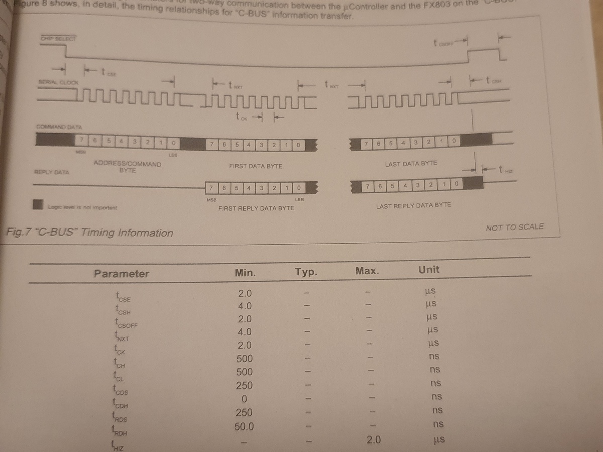
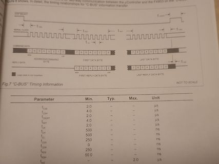
Figure 8 shows, in detail, the timing relationships for "C-BUS" information transfer.
CHIP SELECT
tCSOFF
SERIAL CLOCK
tCS
tCSH
tNXT
tCK
COMMAND DATA
MSB
LSB
ADDRESS/COMMAND BYTE
FIRST DATA BYTE
LAST DATA BYTE
REPLY DATA
MSB
LSB
FIRST REPLY DATA BYTE
LAST REPLY DATA BYTE
tHIZ
Fig.7
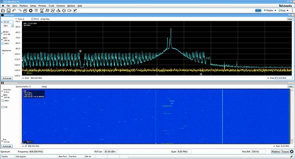
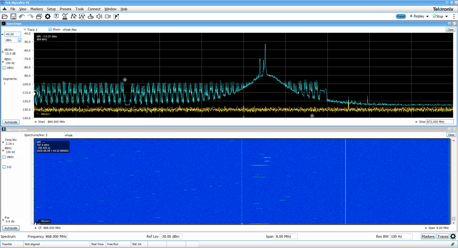
43:32.980852 RBW 100 Hz VBW 3.0 Pos 0.0 div Autoscale More CF 868.000 MHz Span 8.00 MHz Spectrum Transfer Frequency 868.000 MHz Real Time Free Run Ref Lev -30.00 dBm Span 8.00 MHz Res BW 100 Hz Markers Traces
halte die Ada-Syntax fuer schwerfaellig, und VHDL ist eigentlich entsetzlich ineffizient, aber als Transfer-/Simulationssprache ist es immer noch geeigneeter als eine assemblerartige RTL. Wenn es die zugrundelegenden Mechanismen erlauben, robusten Code, der ueber teilidiotische Ansaetze von statischer
Compliant* A = Assembly Location Y = Year Mechanical Characteristics: WW = Work Week CASE: Void-free, transfer-molded, thermosetting plastic xx = Device Code (Refer to page 3) FINISH: All external surfaces are corrosion resistant and leads are G = Pb−Free Package readily solderable (Note: Microdot may be in
MARKING DIAGRAM Pb−Free Packages are Available YWW Mechanical Characteristics: xxxA CASE: Void-free, transfer-molded, thermosetting plastic FINISH: All external surfaces are corrosion resistant and leads are readily solderable Y = Year WW = Work Week MAXIMUM CASE TEMPERATURE FOR SOLDERING PURPOSES: xxxA =
geben kann. Auch wenn das Bezahlsystem selbst keine "Datenspuren" hinterlässt, eine autorisierten Transfer hat es gegeben (sonst "würde ja der Scheck platzen").
www.isocom-micron.com Rev: V02 Release Date: 2024/03/18 4 4N32/4N33 High Isolation Photo Coupler TRANSFER CHARACTERISTICS Parameter Symbol Min Typ. Max Unit Test Condition Note Current Transfer CTR 500 - - % IF=10mA, V CE0V Ratio Collector-Emitter IF= 8mA, Saturation VCE(sat) 1.0 V - - C = 2mA Voltage
More than half of FIFO has been used; 0: FIFO has been used not more than half. SPI single byte transfer end flag. Write 1 to 1 RB_SPI_IF_BYTE_END RW1 reset: 0 1: End; 0: Not end. SPI all byte transfer end flag. Write 1 to 0 RB_SPI_IF_CNT_END RW1 reset: 0 1:All byte transfer ends; 0:All byte transfer
zuverlässig. Der 3 GHz-Bereich basierte auf dem sogenannten ACTO-Prinzip (Automatic Computing Transfer Oscillator). Dabei wurde das Eingangssignal über zwei Mischer in ein Differenzsignal umgesetzt, dessen Frequenz ein Vielfaches einer Referenzfrequenz war – in diesem Fall 1 kHz. Das Besondere: Die
noch niedrigere Datenrate. Häufig gehen Seiten mit 64k nicht, weil der Hoster bei zu langsamen Transfer einfach die Verbindung abbricht. Es gibt auch Anbieter, wie diese ...flares, wenn man denen als Kundschaft etwas auf die Füße tritt, dann geht die Seite auch mit 64k. Ein Kollege war durch die
the feedback loop to keep the output voltage regulated, thus exploiting its frequency-dependent transfer characteristics. 2. Burst-mode control with no or very light load. When the load falls below a value, the converter will enter a controlled intermittent operation, where a series of a few switching
shaped and there is no stage from operating in CCM: as long as the coil discontinuity in the power transfer. current is not null, the power switch is not allowed to Given the dead−time presence, DCM needs a higher peak turn on. Hence the circuit can only operate in either inductor current compared to CRM
falsche Vorstellungen von USB... Die Paketgröße ist bei Fullspeed(1.1) und Bulk fest 64 Bytes pro Transfer. Bei Highspeed(2.0) wären es übrigens 512 Bytes. Auf diese Packet Size hast du aber von der Anwendungsseite keinen Zugriff und musst das auch nicht beachten. Es ist immer Aufgabe des Treibers einen
+ 1 LSB ACK Mμp START ADDRESS WRITE WRITE DATA STOP SLAVE ACK ACK(1) 001aai794 (1) To stop the transfer after the last acknowledge a stop condition must be generated. 2 Fig 15. I C-bus write SCL 1 2 7 8 9 1 2 7 8 9 SDA MSB MSB − 1 LSB + 1 ACK MSB MSB − 1 LSB + 1 LSB Mμp START ADDRESS READ ACK(1) STOP SLAVE ACKNOWLEDGE READ DATA 001aai795 (1) To stop the transfer, the last byte must not be acknowledged (SDA is HIGH) and a stop condition must be generated. Fig 16. I C-bus read TDF8530_SDS All information provided in this document is subject to legal disclaime

 Bild
Bild
 Bild
Bild
 Bild
Bild
 Bild
Bild
 Bild
Bild