MPU/MCU PIC18F6390 ADP-PIC17C75X-Q No Need WPIC18 V5.39 MICROCHIP MPU/MCU PIC18F6490 ADP-PIC17C75X-Q No Need WPIC18 V5.39 MICROCHIP MPU/MCU PIC18F6520 ADP-PIC17C75X-Q No Need WPIC18 V5.39 MICROCHIP MPU/MCU PIC18F6525
Power Supply Service Manual S-27 HM 3.3 Measuring power supply voltages 10/2005 US Issue 3 A B C D E F . S x e 1 8 a t 2 9 a C t h 7 i V h S 5 r 2 o 3 o t z E :P0 X 8 0 T s 8 A o neg ( ( ( ( ( ( 5 1 2 N 1 k n h l y n 3 b b w b r g g = 1 A n x 1 F 6 t 6 6 )k (bL7 D j 2 G 1 1 3 a 6 03 8 1 A 01 3 i 3 1 2
Characteristics= V + 1V; I = 10 mA; T = +25°C. Bold values indicate –40°C ≤ T ≤ +125°C, IN OUT OUT J J unless noted. Parameter Symbol Min. Typ. Max. Units Conditions e , Output Noise Voltage — 400 — C = 10 µF n L (10 Hz to 100 kHz) — 260 — µVRMS C = 33 µF L = 100 mA L Ground Current in — 2 10 MIC29150
Nächste Frevelfrage: Da 2SC5551 bzw. BFU590 ordentlich teuer sind, kann man als Transistoren auch BFU690F einsetzen? Die kosten nur 0,44€ bei Kessler. (Transistor NPN 5,5V 100mA 490mW 18GHz SOT343F) https://www.nxp.com/docs/en/data-sheet/BFU590G.pdf https://www.nxp.com/docs/en/data-sheet/BFU690F.pdf
dBm +10.51 dB, 1.23 NF BFG591 -91 dBm +10.39 dB, 1.28 NF OnSemi PZT2222A -87 dBm +10.57 dB, 1.29 NF (used in the new Chinese WBL-02 loop amp) MOT PN2222A "650" -87 dBm +10.56 dB, 1.32 NF MOT PN2222A "329" -87 dBm +10.59 dB, 1.35 NF BFQ18A -92 dBm +10.34
Latch — Brass with nickel plate on a .160 [4.06] and .250 [6.35] height r versions and LCP on .125 [3.18] l version c L e s Card Slot u Height Dimensions O H J G 0 .125 .325 .304 9 3.18 8.26 7.72 8 .160 .360 .339 5 4.06 9.14 8.61 ) .250 .450 .429 5 6.35 11.43 10.90 ( e f Section A-A O i .400 .003 a [10.16
<D7AF4FB2094D7DD8EC2DCBE1494C911E>] >> /Type /Encoding startxref /Differences [33/exclam 69/E 84/T 87/W/X 1529 99/c/d/e/f 108/l/m 111/o/p 116/t] %%EOF >> endobj Figure 1.2: The PDF output for the T X source in figure 1.1. E 9 objects (here the xref table shows 11 objects, numbered from 0 to 10; object
fall time froIHV 250 ns All except 24FC256 (Note 1) 15 TOF minimum to VILmaximum 10 + 0.1CB C B 100 pF 250 ns All except 24FC256 (Note 1) Input Filter Spike All except 24FC256 16 TSP Suppression — 50 ns (Notes 1 and 3) (SDA and SCL pins) 17 T WC Write Cycle Time — 5 ms (byte or page) 18 Endurance 1,000,000
-bit 5.5V, W = 45 µA -0.375 ±0.25 +0.375 LSb 3.0V, I = 24 µA W (Note 7) Capacitance (P ) C — 75 — pF f =1 MHz, Code = Full-Scale A AW Capacitance (Pw) C W — 120 — pF f =1 MHz, Code = Full-Scale Capacitance (PB) C BW — 75 — pF f =1 MHz, Code = Full-Scale Note 1: Resistance is defined as the resistance
1 17 C 23COC L4 +2.4V CIP P1043 2 PPPIIC P PP 2 PP TPS65261RHBR 023CIP 1PL1 PL22 VDD 3V3 C3 CC3 LQM18FN4R7M00D GND 25 5202CIIP 1 1 1 3 3 3 2 1 1 P 22uF P0 22uF 26 BST1 S P B N S B P S 16 GND LQM18FN4R7M00D PC OC P CO36 2 2 I2706 LX1 M F G O F M BST3 PII151 PC53 5 PI C C1COC CO2 1073CIP I2807 PGND1 C
ATXmega128 PIC (CCS- und XC8/C18-Compiler) PIC12F1840 PIC18F4520 STM32 STM32F4xx (getestet auf STM32F401RE/F411RE Nucleo, STM32F4 Discovery) STM32F10x (getestet auf STM32F103C8T6 Mini Development Board) STM32 mit
bunden. Draht auflöten)! Im Mittelpunkt der Schaltung steht ein Auch bei der Bedienung haben die Auto- PIC16F628 (es ist auch ein PIC16F628A ren an den Verwendungszweck „Motor- verwendbar). Zwei parallel geschaltete steuerung“ gedacht. Ein nützliches Featu- Leistungs-FETs sowie kräftige Freilauf- re istdie
und 6800, nicht aber 6502. Die 8-Bit PICs haben damit ziemliche Nöte, erst die revidierte Vision der PIC18 Architektur kommt damit zurecht. Analog dazu implementierte die 68000 reg32+const16. In der Z8000 gab es diese Variante nur bei load&store, was die Effizienz von C/Pascal deutlich reduzierte.
try to boot CP/M 3.1 using yaze-ag ... Loading CP/M 3.1 ... 62K TPA DRIVES: A B C/ D . F G H I J K L M N O . CP/M 3.1 BIOS for yaze-ag, V 1.11 22.05.2019, Copyright (c) by A.Gerlich A> [/code]
_N 4bool q b b b char D c a c c c signed char C zc c Sc a a unsigned char E uc uc Uc h h short int F s s s s s unsigned short int G us us Us t t int H i i i i i unsigned int I ui ui Ui j j long int J l l l l l unsigned long int K ul ul Ul m m long long _J j z x x1 x2 (__int64) unsigned long long _K
wirklich nichts brauchbares als „normales“ LCD zu geben. Eigentlich wollte ich alles mit einem PIC18F ursprünglich ansteuern. Für die grafischen Displays gibts allerhand für den Arduino und hoffentlich genug Beispiele für meine Anwendungen. Plan ist für eine Simme/ Simson einen digitalen Tacho
noch nehmen, wenn ich den Standard Takt > von 16 MHz gegen einen schnelleren wechsle ? wenn du F_CPU anpasst schon. F_CPU wird/wurde in den Board.txt settings gesetzt! nano.build.f_cpu=16000000L es empfiehlt sich ein neues Device zu intallieren, Beispiel für die alte IDE 1.8.18 für die
Supply Voltage Normal/Flyback Mode Threshold (Shutdown Mode) on Feedback Pin 160 T = 25°C 500 –24 J 490 –22 140 V 480 –20 E A 120 m D ( E 470 –18 A T 100 A FEEDBACK PIN VOLTAGE K E L460 (AT THRESHOLD) –16 P R VC= 50mV O N U 80 N 450 –14 U Y P R P 60 K 440 –12 E P A T S 40 D 430 –10 μ E 420 FEEDBACK
Ethernet-Controller RTL8019AS 337x gewünscht (erhältlich: RTL 8019AS) SPI-Ethernet-Controller ENC28J60 (erhältlich: ENC 28J60-I/*) Microchip PIC 18F4550 (PIC mit USB) | | | | | | | Microchip PIC 18F2585 * gleicher Mindestbestellwert in Österreich und in der Schweiz wie in Deutschland Seit 1.12.10 umgesetzt
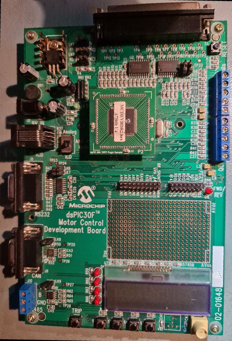
HM2008 Oziloscope ( ist möglich über Service -> Produktservice -> neue Artikel anfragen) Microchip dsPIC30F | | | Microchip PIC 16F883 und 16F886 | Microchip PIC 18F4523 (12/2007: PIC mit 12-Bit A/D-Wandler) * Microchip PIC 18F6585 | Microchip PIC 18F6720 | Microchip PIC 18F8720 | Microchip PIC 24FJ64GB002
ATXmega128 PIC (CCS and XC8/C18 compiler) PIC12F1840 PIC18F4520 STM32 STM32F4xx (tested on STM32F401RE/F411RE Nucleo, STM32F4 Discovery) STM32F10x (tested on STM32F103C8T6 Mini Development Board) STM32 with HAL library
Johannes F. schrieb im Beitrag #7369707: > J. S. schrieb: >> und auch die 5 V Version verträgt höhere Spannungen locker. > > Naja, im Datenblatt steht „bis 1,5 × U_Nenn“, also maximal 7,5 V bei der > 5-V-Version
IF system. Transmitters and Receivers 6 . 1 9 1 AGC Response, 3 MOSFET IF (A) 0 0 - — 81 -10 / "W -f J IF A m p •a m / / I Pa t -so / 1 -« / / £ S "50 f •§* -60 O -160 -140 - DO -100 -80 -60 -40 -20 Pi Receiver InputPower, dBm (C) Fig 6.48—Receiver output vs input for a CW receiver. The threshold was
3,60 OPA335 1 2 1.6 0.001 120 pA 70 pA Vcc-1.5V Vee-0.1V Vcc-15mV Vee+15mV @10kΩ, Vcc-1mV Vee+1mV @100kΩ 0.285 low offset 1µV, Rail2Rail, Vcc=2.7-5.5V, SOT23-5 SO-8, Dual:OPA2335 PDF F 3,50 TL062 2 1 3 3
50V/500mA alle PDF TPIC6B595 1,00 8-fach Low-Side Treiber mit integriertem Schieberegister 45V/250mA F PDF UDN2981 1,50 8-fach High-Side Treiber 50V/500mA R PDF ICL7667 1 Dual inverting MOSFET Treiber 18V, 20ns@1nF R PDF HCPL3120 3.70 Optokoppler mit integriertem MOSFET-Treiber Schaltnetzteile, etc. C
-bit 5.5V, W = 45 µA -0.375 ±0.25 +0.375 LSb 3.0V, I = 24 µA W (Note 7) Capacitance (P ) C — 75 — pF f =1 MHz, Code = Full-Scale A AW Capacitance (Pw) C W — 120 — pF f =1 MHz, Code = Full-Scale Capacitance (PB) C BW — 75 — pF f =1 MHz, Code = Full-Scale Note 1: Resistance is defined as the resistance
inherently ESD sensitive. Handling precautions required. Human body model: 1.5 kΩ in series with 100 pF. ELECTRICAL CHARACTERISTICS Electrical CharacteristiIN:= OUT + 1V; EN ≥ 2.0V;OUT= 100 µA; J = +25°C, bold values valid for –40°C ≤ T ≤ +125°C; unless noted. (Note 1) J Parameter Symbol Min. Typ. Max.

 Bild
Bild