IAXC Input current at AVSS < VIN< AV DD –500 +500 A CI+ and CI– V AOD Differential Output Voltage RL= 78 630 1200 mV |(DO+)–(DO–)| VAODOFF Transmit Differential Output RL= 78 (Note 5) –40 +40 mV Idle Voltage 1584 Am79C961 P R E L I M I N A R Y AMD DC CHARACTERISTICS over COMMERCIAL operating ranges
V = 6.0 V - - 78 - 80 - 80 ns CC CPD power per channel; see Fig. 13 [4] dissipation capacitance V CC = 3.3 V - 28 - - - - - pF V = 5.0 V - 33 - - - - - pF CC 74HC_HCT4851 All information provided in this document is
software: – INTEL AEDIT program editor (or any other program editor) – INTEL ASM51 assembler – INTEL RL51 linker If an assembler or linker other than an Intel is used, the source files must be adapted (assembler and linker control commands might not work with other than Intel tools). 1.2 How to Use This
pF 135 200 ns ACC L Edge of RD to Output Data Valid) = = t1H,0H TRI-STATE Control (Delay CL 10 pF, RL 10k 125 200 ns from Rising Edge of RD to (See TRI-STATE Test Hi-Z State) Circuits) t , t Delay from Falling Edge 300 450 ns W IRI of WR or RD to Reset of INTR CIN Input Capacitance of Logic 5 7.5 pF
3.18 R e s i s t v a l u e s R1 8998K 0,8 % R2 4 K 6 6 8 2 vA R3 898K 0,95 % R 4 5 1 8 E 4 2 A R5 89K78 0,95 % R 6 5 2 K 3 2 Z % R7 9K98 0,95 Zz 3 - 2 7 3.7.6 SA 1045 P D2B driver comparator circuit FUNCTION : Driver comparator Circuit for Domestic Digital Bus D “ B . PACKAGE : 8 pins plastic DIL SOT97C
usingthe+/~ switchtoreversethe me polarity of the trigger level. : + . [ REM (ay, (+/-) , V |T RG RL EEL IPEANETOR COMPARATOR COUNTER AUP . . V Fy O-—o™B VOLTAGE INPOT ATTENUATOR CONVERTOR ; 811127 is S365 Fg.9.Blockdiagram-frequencymeasurements bs 13 1.3.3.2. Time measurements Time measurements of
: Anode grounded scheme in DC output mode O T: TIME K DY1 DY2 DY3 DY4 DY5 P TO PREAMP OR Ip: ANODE RL SIGNAL PROCESSING CURRENT CL CIRCUIT SIGNAL RL: LOAD RESISTOR OUTPUT CL: LOAD CAPACITANCE Rf GND – Cf TO SIGNAL R1 R2 R3 R4 R 5 R6 R7 PROCESSING Cathode grounding scheme in pulse operation + CIRCUIT
rd equ 00h ; 75 76 rp0 equ 05h ;register bank 77 zero equ 02h ;zero bit position in status register 78 carry equ 00h ;carrybit position in status register 79 PC equ 02h ;program counter register 80 81 ;============================================ 82 ; macro definitions 83 ;============================
MHz Output Short-Circuit Current I - 5 - mA SC COMPARATOR AMPLIFIER Small-Signal Voltage Gain AVOL RL= 30kΩ - - - V/V Positive Output Voltage Swing +V O 12 13 - V Negative Output Voltage Swing -VO -2.0 -2.6 - V VOLTAGE REFERENCE Output Voltage VO 1.60 1.75 1.90 V Output Resistance RO - 5 - Ω o Temperature
pro Stunde im Kreis? Mal sehen, ich messe momentan ziemlich genau 5 K Unterschied zwischen VL und RL, für die muss man ... (https://www.omnicalculator.com/de/physik/wasser-erwaermen-rechner) 10,01 kW reinstecken .... Nein! Doch! Oooh! Könnte also der richtige Wert sein. Erklärt auch warum ich noch
Minustemperaturen grenzwertig wurde. Die Tage lief im TV (Tagesschau 24?) ein Film über den Winter 78/79. Anschließend habe ich meine Heizung gestreichelt und zu ihr gesagt: "Gut gemacht!" ;-)
nein _________4 _______44 ja, (EIN) ) DTR, , RS-232)2) nein _________4 _________4 jj, (DTR_HOCH) 2-78 Bedie nung des Univers l ahlers i alzählers Vo reii gestellte We rte na ch de m Ein schaltenn un *RdT eingestellte erte Vor i esteHte W für n ur ü ber d en HP -IB zu gänglichli e Fu nktiotionen Ta e
0x73 Register_74 data 0x74 Register_75 data 0x75 Register_76 data 0x76 Register_77 data 0x77 Register_78 data 0x78 Register_79 data 0x79 Register_7A data 0x7A Register_7B data 0x7B Register_7C data 0x7C Register_7D data 0x7D Register_7E data 0x7E Register_7F data 0x7F P0 data 0x80 SP data 0x81 DPL data
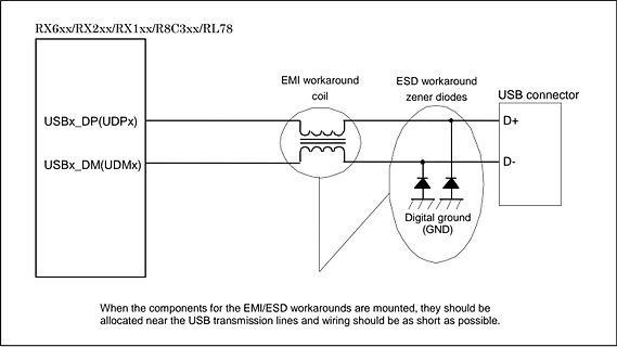
RX6xx/RX2xx/RX1xx/R8C3xx/RL78
USBx_DP(UDPx)
USBx_DM(UDMx)
EMI workaround coil
ESD workaround zener diodes
USB connector
D+
D-
Digital ground (GND)
When the components for the EMI/ESD workarounds are mounted, they should be allocated
Resistance Input 1, 2, 3 35 50 70 K V CL ClippingLevel 2 2.5 Vrms SIN Input Separation (2) 80 100 dB RL Output Load resistance pin 7, 17 2 K G INmin Min. Input Gain -1 0 1 dB G INmax Max. Input Gain 11.25 dB G Step Resolution 3.75 dB STEP eIN Input Noise G = 11.25dB 2 V V DC DC Steps adjacent gain steps
should be above 0.5 Mohms. The average value is 29.99 Mohms. r630005d - 16.10.aa – Dieter Helmich Seite 78 von 122 5.7.1.7 New Gossen 5.7.1.8 Photograph to explain the procedure Code new GOSSEN - 340756 (830 eur) A Must be calibrated every two years (the old model is no longer available) B C A- connection
MM per JESD22-A115 and 1000 V CDM per JESD22-C101 Latch-up testing is done to JEDEC Standard JESD78 which exceeds 100 mA Packages offered: SO24, TSSOP24, HVQFN24 3. Ordering information Table 1. Ordering information Tamb = 40 C to +85 C. Type number Topside Package mark Name Description Version
Γ VSWR = VZ min = 1 − Γ, 1 ≤ VSWR ≤ ∞ If VSWR = 1.0, there is no reflected power. The return loss (RL) is a function of the reflection coefficient but expressed in dB. P RL = 10 × log10 incident = P incident− Preflected Preflected Preflected in dB = Pincident in dB − RL Preflected in dB = Pincident in dB − RL Numerically, RL has a value between 0 dB and ∞. When RL = 0 dB, the reflected power is equal to the incident power and no power reaches the load. The RL is always positive (see document [1]). See Appendix
Peter P. schrieb im Beitrag #7955003: > ich suche einen LDO Spannungsregler SA78RL05F in THT. > Dieser ist verbaut in einem Makita Baustellenradio und liefert 0 Volt Ist er denn auch 'enabled' ? Suchst du R oder RL, das Datenblatt sagt R und 78RL05 ist eine Temperatursicherung
Peter P. schrieb im Beitrag #7955026: > genau der SA78RL05F ist verbaut Das Datenblatt sagt aber SA78R05. *Nicht* SA78RL05 > Ist mit 1,8V enabled und 0 Volt ausgang, ziemlich warm 55° sagt mein > Infrarotthermometer. Dein Datenblatt sagt auf Seite
2 AXR1[7] EMA_D[6] s 0.1/10 2 3 SD3/DSD_FR SD3/DSD_FR R 169 52 1 _ EMA2 A2 5 0A5 EMA5 t ) HWCK/DSD_RL AXR1[6] EMA_D[5] 4 o 2 3 h I HWCK/DSD_RL 170 51 C n C455 EMA3 A3 6 9A4 EMA4 s M SD1/DSD_FC HWCK/DSD_RL AXR1[5] CVDD 2 2 to DIGITAL 1/5 . D SD1/DSD_FC C416 171 50 VDD 7 8VSS H SD2/DSD_LFE DVDD EMA_D[4
exist for all functions. A better transformation is sought. Section 2.1 gave the results of RC and RL networks when driven by a dc source. More explicitly, the drive was the unit step function, u-dt}, formally 0 for t < 0 and 1 for t ~ o. The results for the networks considered were decreasing exponential
30 SHDN IN G1.507 G 1.81 R L L C 25 O1.500 O 1.80 T T T E 20 U U 1.79 S T1.493 T I 15 O O Q 1.486 1.78 10 VIN 6V R = ∞, I = 0 (LT1763-1.5/-1.8/-2.5/-3/-3.3/-5).479 1.77 5 L L 0 RL = 250k,LI = 5µA (LT1763) 1.472 1.76 –50 –25 0 25 50 75 100 125 –50 –25 0 25 50 75 100 125 –50 –25 0 25 50 75 100 125 TEMPERATURE
108 107 106 105 104 103 102 101 100 99 98 97 96 95 94 93 92 91 90 89 88 87 86 85 84 83 82 81 80 79 78 77 76 75 74 73 DIR_INT1 10K 1 1 5 SP_PROT BUS0 1 BUS0 109 S S B K K K T T T E T T T S T C R E K I O W D L A C E N N T S E 72 4 0 U U S C C C S D N N _ N N N V E C R _ C _ _ T _ S D N T D _ S V U R202
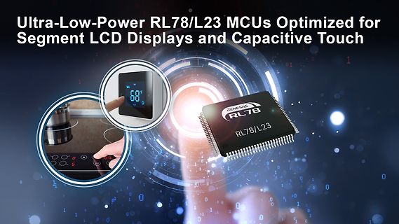
which meet the demands of the EU's Cyber Resilience Act (CRA). [/c] ### Renesas RL78/L23 - neuer 16 Bit-Mikrocontroller Dass Achtbitter und 32-Bitter in verschiedensten Embeddedsystemen werkeln, dürfte hinreichend bekannt sein. Renesas bietet mit der RL78-Familie ein „Zwitterwesen
werden die folgenden heitern Features im Rahmen der Ankündigung hervorgehoben: [c] • 16-bit RL78 microcontroller running at 32MHz • Built-in segment LCD controller and capacitive touch • Up to 512KB of dual-bank flash memory for seamless FOTA • Up to 32KB of SRAM and 8KB of data
oemsecrets Categories FPB-RL78L23 No Distributor Results Found for FPB-RL78L23 Sorry, we can't find any distributors currently listing products for your search "FPB-RL78L23". Please check you have entered only the manufacturer part
Branchennewsdienst Phoronix berichtet unter der URL https://www.phoronix.com/news/GCC-Epiphany-M3C-RL78 nun darüber, dass einige Renesas-Architekturen bald als „deprecated“ markiert werden dürften: [c] The "epiphany" port for the Adapteva Epiphany architecture saw two fixes in 2024 but before that
the last fix for this Renesas M32C 32-bit MCU port being done is all the way back in 2015. The "rl78" port for the Renesas RL78 low-power 8-bit and 16-bit micro-controllers hasn't seen a fix since 2018. [/c] ### Infineon: Übernahme des Automotive Ethernet-IPs von Marvell abgeschlossen. Über
1.0 kX 180 400 kX Output Impedance VINe g 1.0V, L e 50X, RS e 10 kX 6.0 10 X Output Voltage Swing RL e 1.0 kX, IN e g 12V g 10 g 11 V Output Voltage Swing VS e g 15V, VINe g 12V, S e 50X, RLe 100X, TA e 25§C g 10 V e e DC Output Offset Voltage RS 300X, R L 1.0 kX g 10 g 30 mV DC Input Bias Current R e 10 kX, R e 1.0 kX g6.0 g 10 mA S L Harmonic Distortion VINe 5.0 Vrms, f 1.0 kHz 0.1 % Rise Time RL e 50X, DV INe 100 mV 7.0 12 ns Positive Supply Current RS e 10 kX, RL e 1.0 kX a 6.0 a 10 mA Negative Supply Current RS e 10 kX, RL e 1.0 kX b6.0 b 10 mA Note 1: Specification apAli25§C with12V on Pins
SEPARATION AND CHROMA DECODER.........................................................................78 4 ELECTRICAL CHARACTERISTICS ..................................................................................................91 4.1 DIGITAL I/O PAD OPERATION CONDITION..............................
MM per JESD22-A115 and 1000 V CDM per JESD22-C101 Latch-up testing is done to JEDEC Standard JESD78 which exceeds 100 mA Packages offered: SO24, TSSOP24, HVQFN24 3. Ordering information Table 1. Ordering information Tamb = 40 C to +85 C. Type number Topside Package mark Name Description Version
SWITCHING CHARACTERISTICS (V = 5.0 Vdc ± 1%, T = + 25°C, See Figure 3.) CC A Propagation Delay Time (RL= 3.9 kW) tPLH − 25 85 ns Rise Time (RL= 3.9 kW) tTLH − 120 175 ns Propagation Delay Time (RL= 390 kW) tPHL − 25 50 ns Fall Time (RL= 390 kW) tTHL − 10 20 ns http://onsemi.com 3 MC1489, MC1489A TEST CIRCUITS 5.0Vdc RL All diodes V 1N3064 R or equivalent Ein E o R C L 3.0 V 50% 50% C E in TLHand tTHL PLH measured 1/4 Response Node E 10% − 90% O V MC1489A VO tTLH in t THL 1.5 V 1.5 V C L 15 pF = total parasitic capacitance
UART_RBR RO If the DATA_RDY bit of LSR is 1, the XXh received data can be read from this register; V1.1 78 CH572/CH570 Datasheet https://wch-ic.com If FIFO_EN is 1, the data received from UART shift register RSR will be firstly stored in the receiver FIFO, and then read out through the register. Transmit
, solved for H and R L yield: VinON – VinOFF R H ----------–6-------------------------- 15 ⋅0 1.25 RL= R ⋅H ---------------------------------- Vin OFF– 1.25 While the line undervoltage is active there is no PWM activity, thus the Vvoltage (if not CC supplied by another source) continuously oscillates
Switch Status IN1: 2.8 V to 5.5 V TPS2113A 0.1 mF R 1 1 8 STAT IN1 2 7 EN OUT 3 6 VSNS IN2 4 5 CL RL ILIM GND RILIM IN2: 2.8 V to 5.5 V 0.1 mF 1 Please be aware that an important notice concerning availability, standard warranty, and use in critical applications of Texas Instruments semiconductor products

 Bild
Bild
 Bild
Bild
 Bild
Bild
 Bild
Bild