Offtopic: 1,6 Millionen Euro in die Entwicklung für ein Gerät, dass der
Hersteller jetzt selbst bei eBay für 100 bis 200€ verschleudert?
Irgendwas ist da aber kräftig schief gegangen - vielleicht hätte man
sich gleich auf ein gutes, aber für den Hobby-Bastler bezahlbares
Hardware-Design beschränken sollen und die Software von Anfang an durch
die Community entwickeln lassen sollen - OpenSource kann sich für einen
Hersteller lohnen.


Ontopic:
Hab die 4.7 gerade geflasht - läuft soweit ganz gut, konnte beim
fröhlich durch Menüs springen nur eine Sache feststellen:
Bei Source sowohl in Edge als auch Pulse Width kann ich Kanal 1, 2, 3
und External auswählen (hab das W2022A), sobald Math aktiviert ist - ist
Math aus hab ich nur Kanal 1, 2 und External. Hier wird Math also
fälschlicherweise als Kanal 3 bezeichnet, sollte ja besser wie im QM und
Cursor-Menü auch Math heißen.

Schönen Gruß und wie immer: Danke für deine gute Arbeit! :)
Egberto schrieb:
> 1000! - neuer Thread? (ich kurble mir auf dem iPad jetzt schon nen Wolf
> beim scrollen)

Wenn du dich anmeldest, dürfte das wegen der Seitenaufteilung locker
eine Faktor 5 und mehr sparen.
Andre schrieb:
> Puh, alles in allem ist das ganze mittlerweile sehr undurchsichtig und
> wenn man nicht stets am Ball geblieben ist - wie in meinem Fall - weiss
> man mittlerweile nicht einmal mehr, ob die aktuelle Firmware
> 1.2.BF.4.7.zip noch kompatibel zu einem voellig unverbastelten Geraet
> ist.
>
> Ist sie das?
Hallo Andre,

ja sie ist es! Ich entwickle die Firmware grundsätzlich auf einem
unverbastelten W2014A. Alle Extras für die Unterstützung alternativer
Hardware ist grundsätzlich optional und wird entweder von mir auf meinem
"getunten" W2022A entwickelt oder von einigen hier im Forum die mir dann
das Coding freundlicherweise zukommen lassen.


@Jürgen & Sebastian

> Bei Source sowohl in Edge als auch Pulse Width kann ich Kanal 1, 2, 3
> und External auswählen (hab das W2022A),

> Und warum ist "External Trig" jetzt erstmal gesperrt?

Normalerweise prüfe ich alles was mit den Kanälen zu tun hat noch auf
dem W2022A. Hier scheint mir aber was durchgerutscht zu sein. In
Display::Init() bzw. in MenuInit() werden die Menüs extra für die
Zweikanalgeräte angepasst. Da scheint ein kleiner Fehler drin zu sein.
Ich stelle natürlich möglichst schnell eine Korrektur zur Verfügung.

Gruß Hayo
>Wenn du dich anmeldest, dürfte das wegen der Seitenaufteilung locker
>eine Faktor 5 und mehr sparen.

Ach ja, stimmt, hatte ich verdrängt... aber Zeit für Teil 5 ist es aber
wohl trotzdem.

Viele Grüße,

egberto
Jürgen schrieb:

> Und warum ist "External Trig" jetzt erstmal gesperrt?
Hallo Jürgen,

ich wollte das gerade fixen, stelle aber fest das bei mir alles richtig
ist und der Eintrag nicht gesperrt ist. Ist das bei Dir noch aktuell?

Gruß Hayo
Jürgen schrieb:
> Und warum ist "External Trig" jetzt erstmal gesperrt?

Bei mir am W2024 ist es im Menü "Edge" freigegeben und in "Puls Width"
gesperrt.

Gruß
Rainer
Ja,

das ist korrekt. Ich bin der Meinung dass die Pulsweitentriggerung für
Extern nicht funktioniert. Täusche ich mich da? Wenn ja dann gebe ich
das natürlich wieder frei.


@all

Allerdings habe ich gerade festgestellt, dass anscheinend der
Math-Channel bei den 2-Kanalgeräten zwar ausgewählt werden kann, aber
keine Auswirkungen zeigt bzw. versucht den nicht vorhandenen Kanal 3 zu
benutzen.

Diese immer wieder auftauchenden Altlasten machen mich echt fertig. Es
gibt aber auch keine Ecke die einfach mal funktioniert.

Ich werde also die Popupsteuerung mal überarbeiten und das vernünftig
machen.

Liebe Besitzer eines 2 Kanal Gerätes - nicht böse sein, Ihr bekommt
natürlich möglichst schnell Abhilfe.

Dear owner of a 2 channel WELEC DSO please don't worry about not working
math channel as source for QM and cursors. Correction will come soon.

Gruß Hayo
Hayo W. schrieb:
>> Und warum ist "External Trig" jetzt erstmal gesperrt?
> Hallo Jürgen,
>
> ich wollte das gerade fixen, stelle aber fest das bei mir alles richtig
> ist und der Eintrag nicht gesperrt ist. Ist das bei Dir noch aktuell?
>
> Gruß Hayo
>


Das gibt es doch nicht! Jetzt ist es bei Edge freigegeben (W2024A). Ich
bin mir ziemlich sicher, daß es gestern beim F2-Button war, d.h. bei
Edge.
Sorry, vielleicht doch schon das Alter :-(
Jedenfalls funktioniert es jetzt.

Gruß Jürgen
Hallo Hayo,
na also, es scheint bei mir doch noch alles i.O. :-O

Nach Default Setup ist bei Edge External gesperrt. Fragt nicht, wie man
das dann freigeben kann...
Stimmt,

-> wird korrigiert.

Bei Pulsewidth lasse ich es aber gesperrt, oder?

Gruß Hayo
Hayo W. schrieb:
> Bei Pulsewidth lasse ich es aber gesperrt, oder?
>
> Gruß Hayo

Da fehlt meiner Ansicht nach noch ein Stück Programm. Ich kann es auch
schlecht testen, wenn ich übers Menü nicht dorthin komme...
Vielleicht kannst Du es erstmal freigeben und wir sehen dann weiter?

Gruß Jürgen
Jürgen schrieb:
> Nach Default Setup ist bei Edge External gesperrt. Fragt nicht, wie man
> das dann freigeben kann...

Mit Reset/Neustart ;-)

Gruß
Rainer
Ich habe inzwischen die ganze Popuplogik überarbeitet. Es ist jetzt
möglich nicht verfügbare Einträge einfach auszublenden. Dadurch wird die
Initialisierung viel einfacher und das Problem mit dem Math-Channel hat
sich auch erledigt genau wie die ausgegrauten Einträge im Triggersource
Menü.

Gruß Hayo
So, diesmal gibt es keine weitere Kompilation, sondern gleich eine neue
Version. Ich habe die letzten Tage alles an Popuplogik und
Kanalwechsellogik durchforstet was da so drinsteckt und habe etliches
neu geschrieben bzw. erweitert oder gelöscht.

Da fehlte es an allen Ecken und Enden. Ich hatte bei meinen Tests so den
Eindruck als ob das jetzt ganz rund läuft. Ihr seid natürlich
aufgefordert das zu überprüfen.

Besonderes Augenmerk bitte auf den QM-Slotwechsel legen. Da die Tests
recht Zeitaufwändig sind konnte ich nur die wichtigsten Kombinationen
testen.

Die Sollfunktion ist:

Wenn eine neue Messung angefordert wird (mit dem Measure Button), dann
wird diese auf den nächsten freien Slot gelegt. Sind alle Slots belegt,
dann werden die Messungen von rechts nach links weitergeschoben (first
in first out). Die neue Messung bekommt dann den neu freigewordenen Slot
zugewiesen.

Wird jetzt ein Kanal abgeschaltet der bei einer Messung als Sourcekanal
dient, dann muß diese Messung beendet werden, der Slot freigegeben
werden und alle restlichen Messungen linksbündig angeordnet werden.

Das Ganze ist nicht so ganz ohne, da alle Parameter der Messungen an den
neuen Slot übergeben werden müssen. Das ist besonders bei Delay und
Phase etwas aufwändiger, da hier eigene Sourcekanäle verwendet werden.
Bei aktivem Math-Channel als Source wird bei Abschalten von Kanal 1 oder
2 der Math-Channel ebenfalls deaktiviert. Es müssen dann also alle Slots
mit Sourcen des abgeschalteten Kanals und des Math-Channels freigegeben
werden.

Viel Spaß beim Testen, ich freue mich auf die Rückmeldungen.

Gruß Hayo
Angehängte Dateien:
-

USTB-Buffer-8KB.png
4,6 KB
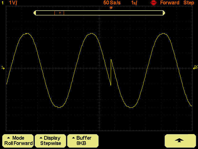
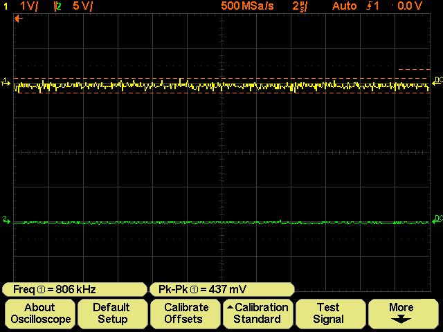
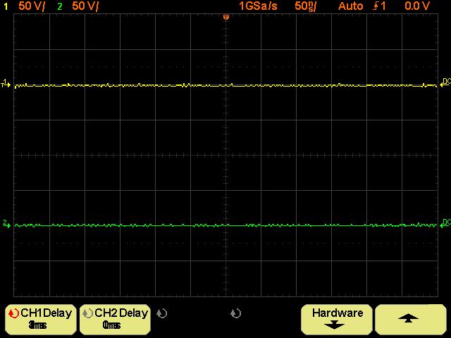
moin moin, Hayo

Ich habe deine 4.8er gerade mal aufgespielt und mal den USTB-Modus mit
einem ca. 100mHz Sinus gefüttert. Wenn der 8KB Buffer voll ist, wird
dieser vor dem nächsten Messzyklus dann nicht geleert?
Auf dem Shot war der Buffer voll, hat von vorne begonnen und
überschreibt die vorherige Messung, ist das Absicht?
Zur Erläuterung: Die Spitze auf dem Shot geht von der neuen auf die alte
Messung, also überschreibt diese.

Gruß Michael
Sieht doch gut aus? Es sollen doch immer möglichst viele
Daten angezeigt werden, deshalb machen das eigentlich alle
Speicheroszilloskope so.

Grüße, Guido
i bin der Meinung die Vertikale Linie duerfte nicht
sein beim Uebergang, aber ansonsten OK

vlG
Charly
Alles ist richtig und gewollt so!

Habt Ihr woanders keine Fehler gefunden? ;-)

Gruß Hayo
Angehängte Dateien:
-

USTB-Dreieck-Buffer-8KB.png
4,8 KB
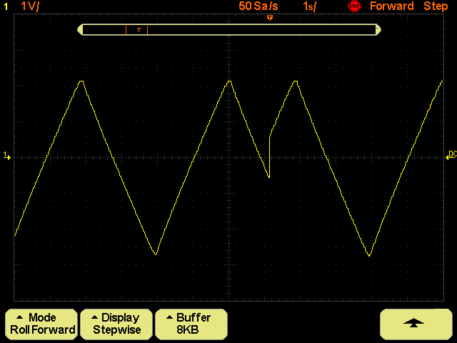
Ok, dann ist ja gut!
Hier habe ich noch ein schickes Dreieck.

Wenn der Singleshot betätigt wird, ist dann der Speicher leer und das
Ganze fängt von vorne an...

Das Messen im QM-Menu läuft jetzt auch etwas flüssiger oder bilde ich
mir das nur ein?

@Hayo,
Ich sollte dich noch an das vierte Messfenster im QM-Menu erinnern...
:-)

Gruß Michael
Ja das vierte Messfenster. Ich hatte das nicht vergessen, im Gegenteil,
ich hatte mir schon Gedanken gemacht ob und wie man das implementieren
könnte. Ich habe zum Ergebnis nur noch nichts gesagt, um den Aufschrei
der Entäuschung zu vermeiden. ;-)

Also - folgende Gründe die dagegegen sprechen:

- einige der Messausgaben sind so breit, dass schlichtweg nicht vier
nebeneinander passen. Nur einige der Ausgaben würden da reinpassen.

- Der zusätzliche Verwaltungs und Programmieraufwand wäre nicht
unerheblich.

- Last but not least - die Rechenleistung unserer kleinen CPU ist mit
drei gleichzeitigen Messungen schon so vollauf beschäftigt, dass eine
weitere Messung den Ablauf fast ganz zum Stillstand bringen würde.

I'm sorry

Hayo
moin,

wenn dem so ist, dann lassen wir das wohl lieber sonst würden wir von
der Performance her, ja rückwärts gehen! Das soll nicht sein und wir
werden's wohl überleben.

Gruß Michael
Hallo,

kennt Ihr die Anschlusseinstellungen ? Ich bekomme keine Verbindung mit
dem Updateprogramm von Welec.

Es ist allerdings ein RS232-USB-Adapter vor dem Notebook eingesteckt.
Verschiedene Baudraten und Einstellungen brachten keinen Erfolg, bleibt
wohl nur noch am PC mit RS232-Schnittstelle auszuprobieren ?
Danke

Gruss

Rolf
Ich vergass: es ist Windows7 auf dem Notebook.
teste mal ob du im Terminal Programm mit 115200
was empfangst beim einschalten des Oszi

vlG
Charly

ps. der original updater iss nix, es gibt hier bessere
Nimm den hier!
Anleitung und Anschlusseinstellungen gibt's hier:
Beitrag "Re: Wittig(welec) DSO W20xxA Open Source Firmware (Teil4)"

Gruß Michael
Die Einstellungen findest Du in der Datei 'How to use a terminal' im
Verzeichnis 'doc'.

Hier noch mal in Kurzform:

Port: hier den benutzten seriellen Port eingeben, meistens COM1
Baud Rate:    115200
Data:     8 bit
Parity:   None
Stop:    1 bit
Flow control:  None

Auch bekannt unter 8N1 115200.

Hast Du den Updater von Markus benutzt? Die beste Lösung ist es das
Perlskript zu benutzen. Dazu mußt Du ActivePerl installieren.

Anleitung auch im 'doc' Verzeichnis Datei

 'How to upload via shell script.txt'

Ansonsten hatte noch ein anderer W20xx Besitzer hier Probleme mit einem
RS232/USB Adapter, ich glaube er hat ein anderes Kabel mit gekreuzten
Leitungen benutzt.

Am besten erstmal wie weiter oben empfohlen testen ob mit dem
Terminalprogram etwas empfangen wird. Wenn alles funktioniert gibt das
DSO beim Hochfahren über die RS232 einige Meldungen aus und nimmt dann
Tastaturbefehle entgegen. Wenn das funktioniert, dann geht auch das
Update mit dem Perlskript.

Wenn Du weitere Fragen hast, nur keine Hemmungen, wir helfen da Schritt
für Schritt weiter.

Gruß Hayo
der Updater den ich gepostet habe, funzt wunderbar!
Wenn er jetzt noch Aktive-Perl installieren soll, sitzt er bis morgen
früh, schätze ich.
Ich benutze auch einen RS232 Adapter(Hama). Es gibt da keine Probleme,
egal ob Notebook oder Tower, die Übertragung dauert nur ein wenig
länger.
Wenn die Anschlusseinstellungen am Rechner(Comport) geändert werden, muß
man den "meistens" neu hochfahren, damit die Einstellungen wirksam
werden.

@Hayo
wer hat denn da ein Kabel gekreuzt???

Gruß Michael
Ich meine ein anderer Michael - Michael W. oder so war das glaube ich.
Da funktionierte das Ganze nur mit einem anderen Zusatzkabel.

Ist aber wohl eher eine Ausnahme. Bei mir läuft das Ganze sowohl am
PC-Port als auch am NoName USB-RS232-Adapter am Notebook problemlos.

Die guten alten echten RS232 Ports...

Tja auf manches kann man eben doch nicht verzichten.

Gruß Hayo
Ach, jetzt hätte ich es fast vergessen: Ich hab heute mit einem alten
Studienkollegen gesprochen und Ihm von unserem Projekt erzählt.
Ergebnis: Er interessiert sich für ein 4 Kanalgerät von WELEC. Wer also
sein Gerät verscherbeln will oder bei Ibähi ein Angot sieht bitte bei
mir melden.

Hayo
Angehängte Dateien:
-

CORRUPTED_1.jpg
45 KB -

CORRUPTED_2.jpg
51 KB -

CORRUPTED_3.jpg
50 KB -

DIMENSION_div_fN.jpg
40 KB -

DIMENSION_div_fN.jpg
41 KB -

DIMENSION_fN_div.jpg
41 KB -

DIMENSION_fN_div.jpg
40 KB -

FFT_Grid_Level.jpg
40 KB -

ZERO_in__QM_.jpg
44 KB -

ZERO_in_QM.jpg
45 KB -

Factory.jpg
39 KB -

High_Freq.jpg
41 KB -

Test_1.jpg
39 KB -

Test_2.jpg
39 KB -

Test_3.jpg
41 KB -

Test_4.jpg
41 KB -

Test_5.jpg
39 KB -

Trg_Lev_Low.jpg
44 KB -

Trig_Lev_High.jpg
46 KB
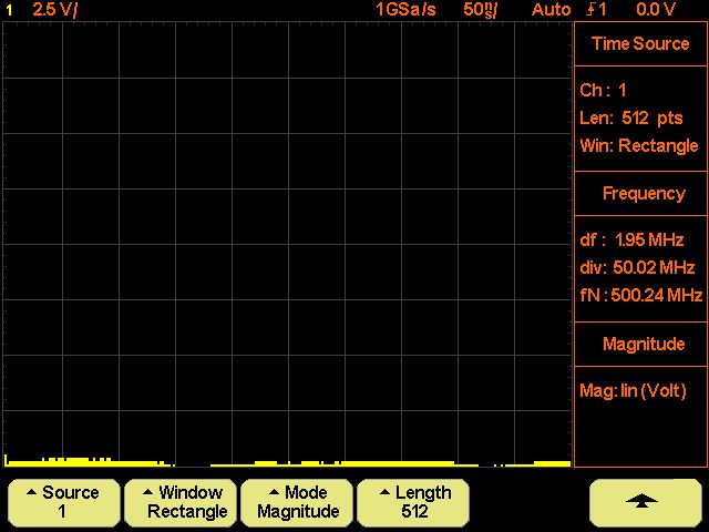
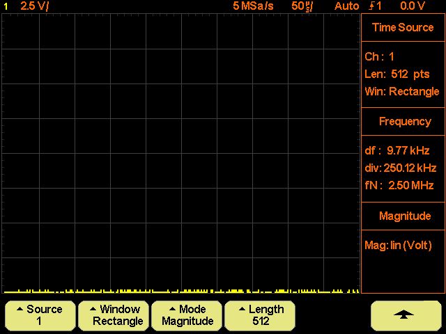
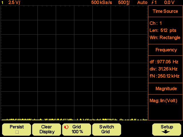

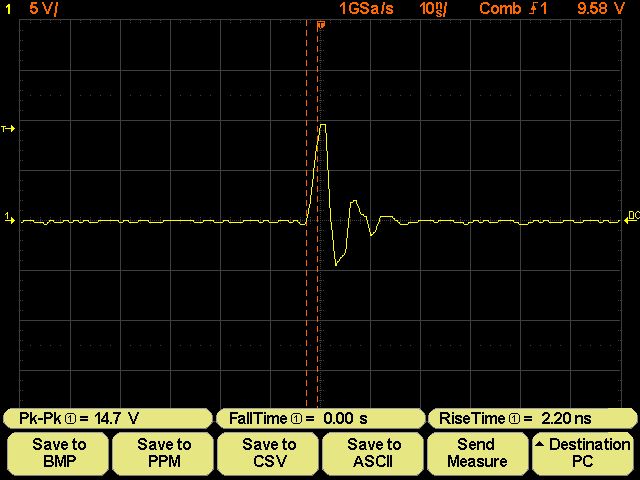
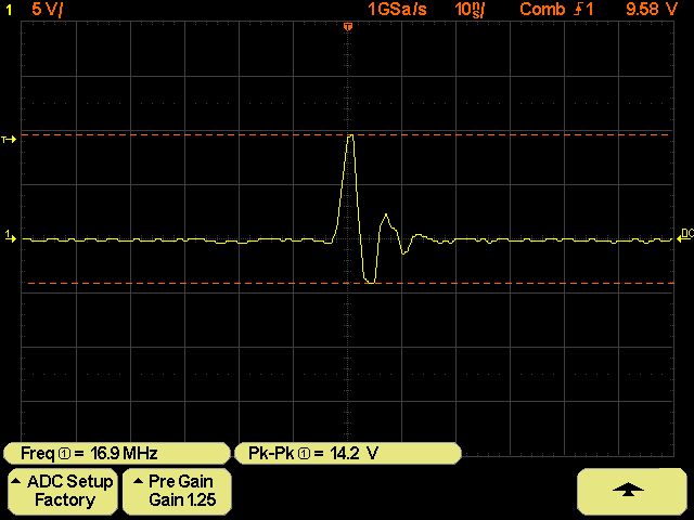
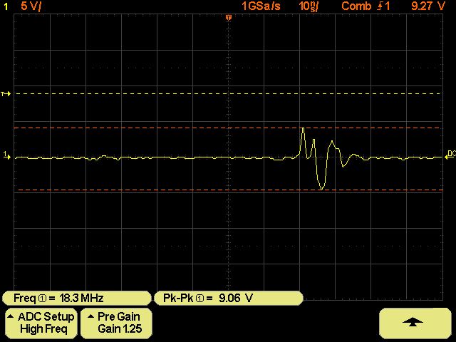


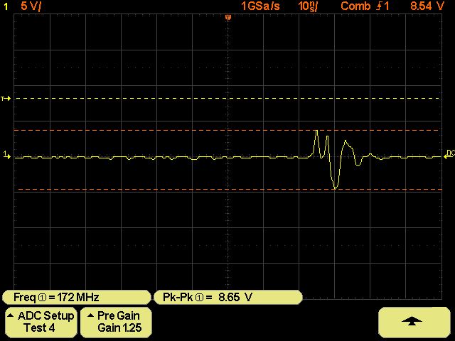

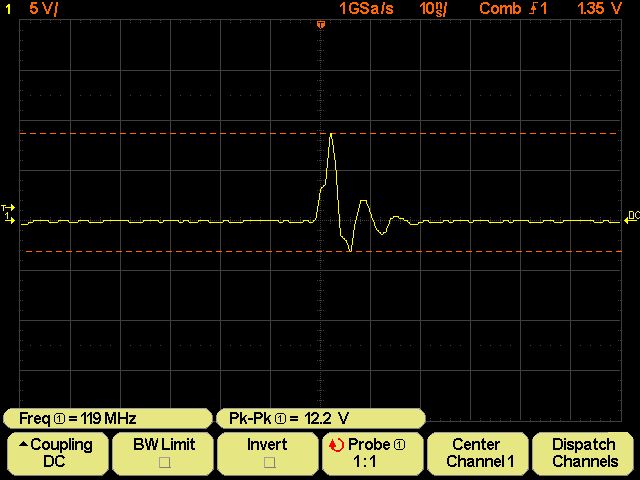
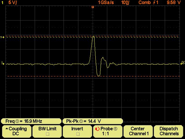
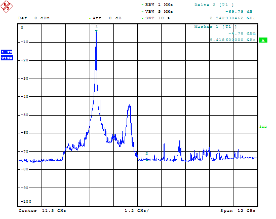
Hi Hayo, Jürgen, and guys all! I am back after a long time. I am in a hurry now, but I want to say some things. Necessarily I will be short. ;-) First I have to thanks all You and especially Hayo for the great work You are doing on Welec's oscilloscopes: no words, RESPECT! I installed the latest firmware release 1.2.BF.4.8 and by the way I noticed some things who I report follow here in order to improve them: mine are not critical to the work done but only for knowledge. Again for knowledge, I specify that all screenshots were made with a W2012A. @Hayo When QM is on, changing Time Base sometimes get corruption on the screen who can be removed by setting to default or performing reset sequence or again by switch between measure's screen to the informations screen: please look at the screenhot CORRUPTED_1.jpg, CORRUPTED_2.jpg, and CORRUPTED_3.jpg. I know the FFT have to be finished in order to improve it, but seems to me the division's value for either df, div and fN are wrong: please look at the screenshot DIMENSION div fN.jpg, DIMENSION fN div.jpg, DIMENSION div_fN.jpg and DIMENSION fN_div.jpg. Again for the FFT when You switch to Display in order to change graticule's dimension, then Grid up to 100% without intensity change and turning the knob the grid's intensity increase but never is possible to set it down, it is stuck until perform default setting: please look at screenshot FFT Grid Level.jpg. About the Quick Measure I noticed when some values are below certain levels then zero is showed: is not possible to increase recognized level in order to show a more low level? For some example please look at the screenshot ZERO in QM.jpg and ZERO in QM_.jpg. About the Hardware ADC Setup, I tried some settings because the behavior of both mine either W2022A and W2012A prevents to use Hig Freq's setting. So right choice is a bit difficult to make for me. Please refer to the screenshot Factory.jpg, High Freq.jpg, Test 1.jpg, Test 2.jpg, Test 3.jpg, Test 4.jpg and Test 5.jpg. Is not there a precise way to make a choice? How can I know if an unknown signal actually appears on screen as in real life or only for the wrong setting of the ADC Setup? Can I get trust or I must to hope it is a right setting? @Hayo, Jürgen As I understand You are trying to further improve either the internal trigger and external, I repeat some things I already wrote. Seems when the trigger's threshold is low the waveform is moving and the signal's amplitude is a bit more low compared to when the trigger's treshold itself is high and so the signal's amplitude becomes it itself more high and the waveform is more steady on the screen. Please refer to my former post and here screenshot Trig Lev High.jpg and Trg Lev Low.jpg. @All Is there somebody noted that signal amplitude seems to depend on the trigger treshold? Is there somebody noted that when the trigger's threshold is low amplitude waveforms on the screen are dancing while when it is much higher the waveforms are much more steady on the screen? @Jürgen Can You kindly explain further about the C37 matter? What are the benefits? And contraindications? Seems to me the modification need for a software support, is not so? Thanks in advance Jürgen. Perhaps the C37 modification together with the change of line and termination resistance for the MAX121 are the minimun to do on the original hardware in order to improve the performances if the Piggyback board is not installed. Of course firmware is much important too. Hayo W. schrieb: >- Last but not least - die Rechenleistung unserer kleinen CPU ist mit >drei gleichzeitigen Messungen schon so vollauf beschäftigt, dass eine >weitere Messung den Ablauf fast ganz zum Stillstand bringen würde. I connect here in order to make some considerations. Of course what You say is right, fast response it is fundamental otherwise the device becomes unusable and useless. In the present and in the past all yours efforts were aimed at improving the device without make it unusable. It is can say the goal was reached, infact now the Welec DSO are much more similar to Agilent and other blasonate DSO's brands and I do not only refering at the features but to the performances too. So there was, there is and there will, I hope, a great improve on either estetic and features: I like very much new configurable screen setting as well some killer applications as Overlay, single shot configuration, new mathematical functions and many others. Said this, I think perhaps > Ich hätte da mal einen Vorschlag: > im Quickmeasure sowie im Curserbereich, stehen fett und breit, 3x > Messbereiche zur Verfügung! > Wäre es möglich, diese Anzeigen um ein Drittel (Breite)zu verkleinern > und einen vierten Messbereich dazu zzu nehmen? Genug Platz ist ja > voranden. it do not kill ours DSO, is not so? I know, this and other things are already in the wish list, but since there was also talk of aesthetic improvements I wanted to remember also this. About the wish list: What about the sin(X/X) interpolation implementation? And centre and span features for the FFT? Now I must to run away, so thank You to all You. Vielen Dank!!! Gruß Luc
Hayo W. schrieb:
> Ich meine ein anderer Michael - Michael W. oder so war das glaube ich.
> Da funktionierte das Ganze nur mit einem anderen Zusatzkabel.
>
> Ist aber wohl eher eine Ausnahme. Bei mir läuft das Ganze sowohl am
> PC-Port als auch am NoName USB-RS232-Adapter am Notebook problemlos.
>
> Die guten alten echten RS232 Ports...
>
> Tja auf manches kann man eben doch nicht verzichten.
>
> Gruß Hayo

Hi,
hat sich inzwischen erledigt mit dem Interface: Ich hab's nochmal ohne
Zusatzkabel probiert und dann ging's doch. Weiss auch nicht, woran's
damals gelegen hat...

Zwischenzeitlich hatte ich tatsächlich überlegt, meinen 4-Kanäler zu
verjubeln aber dank der wieder erstarkendne Entwicklung bin ich wieder
dabei. Inzwischen habe ich noch schöne Aluknöppe gemacht (gibt'n schönen
Beitrag im Hardwarethread) und mit der Firmware ist's wirklich gut
brauchbar.

Leider sind mir die Lötereien für die Huckepackplatinchen zu schwierig,
da trau' ich mich nicht so ran, olles Vogelfutter... :-/

Michel
> Inzwischen habe ich noch schöne Aluknöppe gemacht (gibt'n schönen
> Beitrag im Hardwarethread) und...

War der Beitrag von mir?
Zeig' mal deine Knöppe, dann halt im HW-Thread

Gruß Michael
Luc schrieb:
> Hi Hayo, Jürgen, and guys all!

Hi Luc, welcome back!

> Necessarily I will be short. ;-)

Yes, I know, You are allways short ;-)

> @Hayo
> When QM is on, changing Time Base sometimes get corruption on the screen
Yes I noticed this too and I'm searching for the reason. I hope I can
fix it soon.

> I know the FFT have to be finished in order to improve it, but seems to
> me the division's value for either df, div and fN are wrong:
I guess the values are correct. For example:
Sample Rate 1GSa/s -> fN (span) = Sample Rate/2 = 500MHz
Points = 512 -> Spectrum = 512/2 = 256. Grid width is 512 -> one
frequency line is 2 pixels wide.
div = fN/10 = 50MHz = 50 Pixel wide.
df = div/25 = 2MHz (one line is 2 pixel wide at 512 point FFT)
am I right?

>
> Again for the FFT when You switch to Display in order to change
> graticule's dimension...
Yes You are right, there is a bug. I'm working on it. Thanks.


> About the Quick Measure I noticed when some values are below certain
> levels then zero is showed:
Hmmm, difficult. I think it is because of the interpolation. I will
check if it can be improved.


> About the Hardware ADC Setup, I tried some settings because the behavior
> of both mine either W2022A and W2012A prevents to use Hig Freq's...
Yes this is a Problem. The adjustments with the best HF-behaviour have a
problem with spikes which seem to be generated by wrong FPGA timing. So
I called them Test 1 and Test 2 because they seem to be more
experimental, but may be helpful at very high frequencies. On normal
purposes the factory setting should work ok.

> @Hayo, Jürgen
> Seems when the trigger's threshold is low the waveform is moving
correct, trigger is more stable when the level is not zero but a little
bit higher. The wave form differs because of the zoom effect of some
timebases. at 50ns/div the zoomfactor is 1 and it shouldn't occur.


> About the wish list:
> What about the sin(X/X) interpolation implementation?
I investigated in this theme but it is not trivial. Unfortunately I
didn't find a good implemention example (as code), but only theoretic
descriptions. I'm working on it...

> And centre and span features for the FFT?
Yes this is also on my list and also a 2048 point FFT if possible with
the CPU performance.

Thanks for Your short report,

Hayo
Luc schrieb:

Hi Luc,

> @Hayo, Jürgen
> As I understand You are trying to further improve either the internal
> trigger and external, I repeat some things I already wrote.
> Seems when the trigger's threshold is low the waveform is moving and the
> signal's amplitude is a bit more low compared to when the trigger's
> treshold itself is high and so the signal's amplitude becomes it itself
> more high and the waveform is more steady on the screen.

Yes, this is the same on internal and external trigger. When the
trigger's treshold is high the waveform is more steady on the screen. On
the internal trigger the trigger logic sees more noise and this is why
you have more trigger events on a zero trigger level. The waveform is
moving on the screen.

>@Jürgen
>Can You kindly explain further about the C37 matter?
>What are the benefits?
>And contraindications?
>Seems to me the modification need for a software support, is not so?
>Thanks in advance Jürgen.

On external trigger this new capacitor to C37 reduce the amplitude of
the reference voltage of the external trigger comparator U6, because
this reference voltage is build by a PWM signal and a low pass filter.
So there is with this additional C a more stable timing and the
waveforms are not so much "dancing".
There are no con's. You can use this hardware modifcation also with the
original firmware 1.4.

Regards, Jürgen
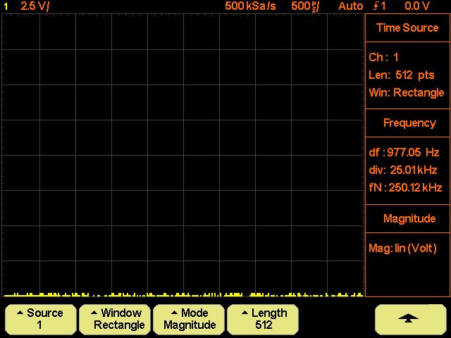
Hi Hayo and guys all! Hayo W. schrieb: >Yes, I know, You are allways short ;-) Oh man, as usual You are right! :-) You certainly know your chickens! ;-) Hayo W. schrieb: >> When QM is on, changing Time Base sometimes get corruption on the screen >Yes I noticed this too and I'm searching for the reason. I hope I can >fix it soon. For sure you will succeed, I will bet on it! Hayo W. schrieb: >> I know the FFT have to be finished in order to improve it, but seems to >> me the division's value for either df, div and fN are wrong: >I guess the values are correct. For example: >Sample Rate 1GSa/s -> fN (span) = Sample Rate/2 = 500MHz >Points = 512 -> Spectrum = 512/2 = 256. Grid width is 512 -> one >frequency line is 2 pixels wide. >div = fN/10 = 50MHz = 50 Pixel wide. >df = div/25 = 2MHz (one line is 2 pixel wide at 512 point FFT) >am I right? Yes of course I think You are right, but I was referring to numerical values in the lateral table and not to the physical size of the graticule. Looking at screenshot DIMENSION_div_fN.jpg with 1Gsa/s and 512pts it is: df=1.95MHz div=50.02MHz fN=500.24MHz And further looking at screenshot DIMENSION_div_fN.jpg with 500Ksa/s and 512pts it is: div=977.5Hz div=25.01KHz fN=250.12MHz Seems to me that the accounts do not come back, is not so? Maybe I am wrong, otherwise sorry, I do not understand. Hayo W. schrieb: >> Again for the FFT when You switch to Display in order to change >> graticule's dimension... >Yes You are right, there is a bug. I working on it. Thanks. Thank You a lot Hayo! Hayo W. schrieb: >> About the Quick Measure I noticed when some values are below certain >> levels then zero is showed: >Hmmm, difficult. I think it is because of the interpolation. I will >check if it can be improved. You knew the job was difficult when you took it, Hayo! ;-) Ok, no kidding anymore, I know it is not simple because in this case it is to push the measure under the nS value, pratically in the pS's field: really not easy! Hayo W. schrieb: >> About the Hardware ADC Setup, I tried some settings because the behavior >> of both mine either W2022A and W2012A prevents to use Hig Freq's... >Yes this is a Problem. The adjustments with the best HF-behaviour have a >problem with spikes which seem to be generated by wrong FPGA timing. So >I called them Test 1 and Test 2 because they seem to be more >experimental, but may be helpful at very high frequencies. On normal >purposes the factory setting should work ok. Yes, thank You for the explanation, Hayo! The real problem is some setting are ok with waveforms as for example the inner probe compensation's generator but are worst with other kind of waveforms as for example pulses. Not easy set it correctly because could happen with a not suitable waveform. And yes, Factory setting work well apart some spikes problem in some circumstance, but upon a time with a former firmware release High Freq setting was the better choise for all the situations. I am sure one of the setting it is the right answer also this time, I will pursue it! Hayo W. schrieb: >> Seems when the trigger's threshold is low the waveform is moving >correct, trigger is more stable when the level is not zero but a little >bit higher. The wave form differs because of the zoom effect of some >timebases. at 50ns/div the zoomfactor is 1 and it shouldn't occur. Thank You very much also for this explanation, Hayo! I guess this even affects the amplitude. Hayo W. schrieb: >> About the wish list: >> What about the sin(X/X) interpolation implementation? >I investigated in this theme but it is not trivial. Unfortunately I >didn't find a good implemention example (as code), but only theoretic >discriptions. I'm working on it... Hayo, this is really an amazing news, thanks! I guess this implementation can improve a lot the shape of the waveforms shown on the screen. Hayo W. schrieb: >> And centre and span features for the FFT? >Yes this is also on my list and also a 2048 point FFT if possible with >the CPU performance. Oh boys, another great amazing news, thank You Hayo, You are really the best one: RESPECT! Hayo W. schrieb: >Thanks for Your short report, Ok, ok, actually it is not so short! ;-) Instead, thanks to You Hayo for the great patience and kindness and free time You provided generously to us!!! RESPECT!!!!!!! Vielen Dank!!!!!!! Mit freundlichen Grüßen, Luc
Hi Jürgen and guys all!

Jürgen schrieb:
>> Seems when the trigger's threshold is low the waveform is moving and the
>> signal's amplitude is a bit more low compared to when the trigger's
>> treshold itself is high and so the signal's amplitude becomes it itself
>> more high and the waveform is more steady on the screen.
>
>Yes, this is the same on internal and external trigger. When the
>trigger's treshold is high the waveform is more steady on the screen. On
>the internal trigger the trigger logic sees more noise and this is why
>you have more trigger events on a zero trigger level. The waveform is
>moving on the screen.
Thank You very much for the explanation, Jürgen: RESPECT!

Jürgen schrieb:
>>Can You kindly explain further about the C37 matter?
>
>On external trigger this new capacitor to C37 reduce the amplitude of
>the reference voltage of the external trigger comparator U6, because
>this reference voltage is build by a PWM signal and a low pass filter.
>So there is with this additional C a more stable timing and the
>waveforms are not so much "dancing".
>There are no con's. You can use this hardware modifcation also with the
>original firmware 1.4.
Very well Jürgen, I thank You a lot for these useful informations:
RESPECT!!!!!!!
For me, and I guess for somebody else also, this is really a very
interesting thing.
Going ahead, in relation to what You wrote this means there are other
capacitors can be modified putting in parallel of them more capacitors
in order to get a better behavior of the inner trigger, due C37 improve
only the external one if I am no wrong.
So, which are the capacitors and what is the final capacitance's value?

Jürgen, thank You very much for the kind reply: RESPECT!
Vielen Dank!!!!!!!

Mit freundlichen Grüßen,

Luc
Luc schrieb:
> Hayo W. schrieb:
>>Yes, I know, You are allways short ;-)
> Oh man, as usual You are right! :-)
> You certainly know your chickens! ;-)

rofl

<ot>
Ok, I learned: 3 pages and about 20 screenshots are defined as "short"
(for Luc). For all the others: 3 lines and max 2 shots, please. ;-)
</ot>

Have a nice sunday, Rainer
Hayo W. schrieb:
>>> About the Hardware ADC Setup, I tried some settings because
>I am sure one of the setting it is the right answer also this time, I
>will pursue it!

The Test 1 is the old High Frequency setting. I only changed the name!
The actual High Frequency Setting does not work so good as the old one
but doesn't has spikes.

Regards Hayo
Hi, here some fixes.


> Again for the FFT when You switch to Display in order to change
> graticule's dimension, then Grid up to 100% without intensity change and
> turning the knob the grid's intensity increase but never is possible to
> set it down, it is stuck until perform default setting: please look at
> screenshot FFT Grid Level.jpg.

Solved

> About the Quick Measure I noticed when some values are below certain
> levels then zero is showed: is not possible to increase recognized level
> in order to show a more low level?

Solved -> measuring is now possible with pico second resolution.


- Holdoff now is switched off at pulse width triggering

Hayo
moin moin Hajo & Co.

wenn du die  Y pos auf die 2. unterste Linie stellst
und dann utility/calib. offset ausfuerst und dann mit
Y pos. fast ganz nach oben wanderst verdoppelt (ca.)
sich das dargestellte Rauschen ;(
ungekehrt ist der efekt aber ebebso (kalibrate ganz
oben).
vielleicht kann das mal noch jemand testen ob das
generell oder nur bei meinem so ist

vlG
Charly
Hi Charly,

> wenn du die  Y pos auf die 2. unterste Linie stellst
> und dann utility/calib. offset ausfuerst und dann mit
> Y pos. fast ganz nach oben wanderst verdoppelt (ca.)
> sich das dargestellte Rauschen ;(
Stimmt, das war schon immer ein kleines Problem, also auch bei meinem
Welec (2022A)!

> ungekehrt ist der efekt aber ebebso (kalibrate ganz
> oben).
Stimmt auch!
Das kommmt daher, das dann die Nulllinie nicht hinterher kommt.
Ist die Linie ganz unten, sitzt Diese ca. 2 Pixel unter Null, umgekehrt
dann 2 Pixel darüber und das Rauschen nimmt ebenfalls zu, weil dann die
Kalibrierung für oben u. unten nicht mehr stimmt.

> vielleicht kann das mal noch jemand testen ob das
> generell oder nur bei meinem so ist
und nein, das ist nicht nur bei dir so!
Das war aber in der Vergangenheit schon mal Thema, frag' mich jetzt blos
nicht, wo das mal war...

> vlG
> Charly

Gruß Michael
Stimmt bei Euch die Nulllinie nicht? Muß ich da die Skalierung noch
anpassen? Ich dachte eigentlich das passt ganz gut. Habt Ihr die
Eingangswiderstände modifiziert oder so?

Gruß Hayo
Hi Hayo,  Rainer W., charly, Michael D., and guys all!

Hayo W. schrieb:
>Solved
Hayo, thank You very much for the fix: RESPECT!

Hayo W. schrieb:
>Solved -> measuring is now possible with pico second resolution.
Oh boys, this is really incredible and make me very happy!
Hayo You are the best one, no words: RESPECT!!!!!!!
I must to say the Welec oscilloscopes are a lot improved and now their
are can compete with other blasonate DSO's brands on the market.
Today I finally managed to complete some measures with the sole help of
my W2022A without necessarily having to use other tools.
All this thanks to your great work Hayo and all who are involved in the
Welec project, so I thank all You again: RESPECT!!!!!!!

Hayo W. schrieb:
>The Test 1 is the old High Frequency setting. I only changed the name!
>The actual High Frequency Setting does not work so good as the old one
>but doesn't has spikes.
Great news, thank You very, very much Hayo!
Also this information aid me very much, now I know what is the better
choice even without necessarily take a look at all the options.
This is amazing for me also because I have not all the necessary
strumentation in order to investigate the matter.
Perhaps is not it better return the name?
Anyway thank You again Hayo: RESPECT!

@Rainer W.
Selbst wenn ich zu spät Ich erwidere den schönen Sonntag. :-)
I hope to have been understood. :-)

@charly, Michael D.
Sorry but I do not understand very well.
I even have a W2022A and maybe I can check it, so please can You explain
me what is the problem?
Thanks!

Vielen Dank!!!!!!!

Mit freundlichen Grüßen,

Luc
Hi Hayo and guys all!

@Hayo
Maybe I found a little bug in a 1.2.BF.4.8C2 firmware.
Setting channel delay in Hardware menu, values are not update by rotary
knob but only by push the buttons, but still on this by changing the
other delay's channel then get corruption on the screen's tag.
DSO is W2022A.

Mit freundlichen Grüßen,

Luc
@Hajo

nullinie stimmt schon, nur das rauschen verdoppelt sich,
i werd mal versuchen es mit bilder darzustellen sobald
i a bissel zeit habe (im moment muss i auch softw. f.
einen kunden anpassen)

@Luc
i will post a few pics so fast as possible

vlG
Charly
Hallo Hayo (und Huckepack-Platinenkunden),

nach etwas Pause (andere Projekte...) habe ich mir am Wochenende die
aktuelle Version von Hayo gesaugt, um für die nun in Alphaversion
unterstützte Eingangsplatine die Kalibrierwerte in der Software zu
ermitteln. Hier die dafür nötigen Code-Änderungen. Meine Basis ist die
Version 1.2.BF.4.8C2.

Erst tat sich praktisch nichts, die Platinen wurden nicht sinnvoll
initialisiert. Als Ursache habe ich mein zu straffes Timing gefunden,
das war grenzwertig. Mitunter war das FPGA mit seinem SPI-Transfer noch
nicht fertig wärend ich die nächste Flanke anfordere, es wurden Bits
verschluckt. Also bitte anpassen, in Zeile 41 von tc_vars.h:
1 | #define SPI_DELAY16 175 // >150 us for shifting out a 16 bit value
|
Zur Sicherheit habe ich in hardware_t.cpp in Zeile 2908 die
Rest-Warteschleife durch folgenden Block ersetzt:
1 | if ((15000-49*SPI_DELAY16) > SPI_DELAY16) // if there's still more time to kill than the shift time |
2 | {
|
3 | Sleep_us(15000-49*SPI_DELAY16); // wait for SPI shifting it out, plus remaining relay settling time |
4 | }
|
5 | else // minimum time |
6 | {
|
7 | Sleep_us(SPI_DELAY16); // wait for SPI shifting it out |
8 | }
|
Das ist falls jemand SPI_DELAY16 so groß definiert, das die Relay
Settling Time bereits erreicht wird. Sonst warten wir für eine negative
Zeit, das könnte u.U. sehr lange dauern...  ;-)
Das if() kann bereits der Compiler auswerten, kostet also nichts.

So, nun konnte es an die Kalibrierung gehen. Ich habe die letzte Spalte
für ScaleFactor[] und DAC_ScaleFactor[] per DC-Messung an einem Kanal
ermittelt. Hoffentlich ist die Streuung gering.
In tc_vars.cpp ab Zeile 1084:
1 | float ScaleFactor[16][5] ={ {3.25, 2.615, 3.309, 3.875, 1.822}, // 1mV |
2 | {3.25, 2.615, 3.309, 3.875, 1.804}, // 2mV |
3 | {2.095, 2.095, 2.697, 3.125, 1.799}, // 5mV |
4 | {3.25, 2.615, 3.309, 3.875, 1.822}, // 10mV |
5 | {3.25, 2.615, 3.309, 3.875, 1.804}, // 20mV |
6 | {2.095, 2.095, 2.697, 3.125, 1.799}, // 50mV |
7 | {3.25, 2.615, 3.309, 3.875, 1.822}, //100mV |
8 | {3.25, 2.615, 3.309, 3.875, 1.804}, //200mV |
9 | {2.095, 2.095, 2.697, 3.125, 1.799}, //500mV |
10 | {3.25, 2.615, 3.309, 3.875, 1.822}, // 1V |
11 | {3.25, 2.615, 3.309, 3.875, 1.804}, // 2V |
12 | {2.095, 2.095, 2.697, 3.125, 1.799}, // 5V |
13 | {3.25, 2.615, 3.309, 3.875, 1.822}, // 10V |
14 | {3.25, 2.615, 3.309, 3.875, 1.804}, // 20V |
15 | {2.095, 2.095, 2.697, 3.125, 1.799}, // 50V |
16 | {3.25, 2.615, 3.309, 3.875, 1.822}}; // 100V |
und ab Zeile 1134:
1 | float DAC_ScaleFactor[3][5] = {{ 2.480, 2.480, 2.6456, 2.520, 16.361 }, // 1er ranges |
2 | { 4.940, 4.940, 5.2912, 4.980, 30.503 }, // 2er ranges |
3 | {12.360,12.360,13.2280,12.432, 76.505 }}; // 5er ranges |
(Code bei Sourceforge aktuell halten wäre cool, das erspart uns beiden
diese Handarbeit.)
Das mögen noch nicht die endgültigen Werte sein, aber zumindest schon
mal eine Ausgangsbasis.

Es bleibt noch ein Offset-Problem. Mit der automatischen Kalibrierung
kriege ich das Ding nicht auf Null. Vielleicht entartet irgendwo die
Numerik, die neuen Faktoren sind ja schon recht anders. In den 5er
Bereichen ist die Signallinie ca. 1 Kästchen höher als die DC-Marke, in
den 2er Bereichen ca. 3 Kästchen, in den 1er Bereichen gut 5,5 Kästchen.

Hmm, ich bemerke gerade ein sehr seltsames Verhalten: Der Offset-Regler
von Kanal 3 beeinflußt den Offset von Kanal 4, und zwar gegensinnig. Für
Kanal 3 hingegen ist der Regler wirkungslos. Damit kriege ich immerhin
meinen zur Messung verwendeten Kanal 4 auf Null. Hat noch jemand aktuell
so eine Wechselwirkung, oder spinnt meine Hardware?

Grüße,
Jörg
Jörg H. schrieb:
> Hat noch jemand aktuell
> so eine Wechselwirkung, oder spinnt meine Hardware?

Beim W2024 ohne Hardwareumbauten funktioniert die Offseteinstellung für
alle 4 Kanäle ohne Seiteneffekte.
Hast du den obligatorischen Default Setup (Utility) durchgeführt?

Gruß
Rainer
Hallo Jörg,

deine Probleme interessieren uns nicht die Bohne. :-))

Wir wollen wissen, wie es mit der Huckepackplatine aussieht!

Hast du HF-Messmöglichkeiten? Ich meine ja, sonst müssten wir
noch etwas unternehmen.

Grüße, Guido
Ich übernehme die neuen Änderungen natürlich sofort und gebe so schnell
wie möglich eine neue Version raus.

Gruß Hayo
@Guido

>deine Probleme interessieren uns nicht die Bohne. :-))
>Wir wollen wissen, wie es mit der Huckepackplatine aussieht!
ich nehme an, dass Du das lustig gemeinst hast was Du da in 'unserem'
Namen geschrieben hast, diese Art kannst Du aber m.E. -so- ruhig stecken
lassen.
Guido schrieb:
> deine Probleme interessieren uns nicht die Bohne. :-))
>
> Wir wollen wissen, wie es mit der Huckepackplatine aussieht!

Oder war das etwa eine Anspielung auf mich...?

Soweit ich weiß, wurden die HF alle Messungen (vor langer Zeit)
erfolgreich von branadic durchgeführt und auch gründlich dokumentiert.

Jörg befasst sich nur noch mit dem Einbau und der Ansteuerung in der
Firmware. Außerdem gab es noch ein kleines ESD Problem, dass noch
geklärt werden muss.

Mfg,
Kurt
Robert schrieb:
> ich nehme an, dass Du das lustig gemeinst hast

Na klar, deshalb auch der Smiley hintendran. Ich denke Jörg wird das
schon richtig verstehen. Ich glaube aber nicht, dass ich der einzige
bin, der sehr gespannt erwartet, was Walters und Branadics Werk in
der Praxis bringen. Jörg ist schließlich der Erste, der es zur
Funktion bekommt.
Luc schrieb:

> Maybe I found a little bug in a 1.2.BF.4.8C2 firmware.
> Setting channel delay in Hardware menu, values are not update by rotary
> knob but only by push the buttons, but still on this by changing the
> other delay's channel then get corruption on the screen's tag.
> DSO is W2022A.

Oh man, how did You make it? I tried hard but all is ok, except the gray
turn arrows which appear on the empty two places after pushing the
button 1 or 2.

Hayo
Hui, hier ist ja was los. Passt schon, keine Empfindlichkeiten.

Das mit dem Geister-Offset muß ich mir also nochmal auf meiner Hardware
anschauen.

Ansonsten ist jetzt langsam der Zeitpunkt gekommen, wo auch andere Leute
sich die Platinen einbauen können. Dann gibt es auch mehr Erfahrungen
damit. Wohlmöglich sogar von Leuten, die das Oszi praktisch einsetzen
(ich gehöre nämlich noch nicht dazu).

Was ich weiterhin noch schreiben wollte:
Die Ansteuerung kann man vermutlich noch insofern optimieren, daß man
die Bildschirmhöhe und die Aussteuerung der ADCs mehr zur Deckung
bringt. Im Moment kriege ich auch recht weit außerhalb des sichtbaren
Bereichs noch sinnvolle Meßwerte, die ADCs sind auch dort noch nicht in
Vollaussteuerung. Ich nehme an, das ist nicht so gewollt. Wir
verschenken also sichtbare Auflösung und zeigen auch unnötig großes
Rauschen.
Der Chip auf der Eingangsplatine hat eine programmierbare Verstärkung,
wir können die also reduzieren und recht fein aufeinander abstimmen.

Ich habe kein HF-Equipment (und auch wenig Ahnung davon). Kann sein, daß
da auch noch was zu holen ist. Die Rechtecke des Testgenerators haben
mit 1:10 Tastkopf etwas schräge Dächer. Vielleicht ist da noch was
suboptimal, oder ich sollte am Tastkopf drehen.

Grüße
Jörg
Jörg H. schrieb:

> Ansonsten ist jetzt langsam der Zeitpunkt gekommen, wo auch andere Leute
> sich die Platinen einbauen können. Dann gibt es auch mehr Erfahrungen
> damit.
Ich komme erstmal nicht dazu weil ich nächste Woche im Urlaub auf
Sardinien bin.


> Was ich weiterhin noch schreiben wollte:
> Die Ansteuerung kann man vermutlich noch insofern optimieren, daß man
> die Bildschirmhöhe und die Aussteuerung der ADCs mehr zur Deckung
> bringt. Im Moment kriege ich auch recht weit außerhalb des sichtbaren
> Bereichs noch sinnvolle Meßwerte,

Das ist bei den original Eingangsstufen leider auch so. Wenn man die
Verstärkung so umprogrammieren könnte, dass Fullscale knapp über
Gridhöhe liegt, dann wäre das auf jeden Fall sehr sachdienlich.

Allerdings müßten dann die Scalefaktoren noch mal angepasst werden.

Gruß Hayo
@Luc & all others

>> When QM is on, changing Time Base sometimes get corruption on the screen
>Yes I noticed this too and I'm searching for the reason. I hope I can
>fix it soon.

Unfortunately I wasn't able to reproduce this problem. Has anyone an
idea how to force this error? Otherwise it is a littlebit difficult to
analyze the problem.

Regards Hayo
Hayo W. schrieb:
>> Was ich weiterhin noch schreiben wollte:
>> Die Ansteuerung kann man vermutlich noch insofern optimieren, daß man
>> die Bildschirmhöhe und die Aussteuerung der ADCs mehr zur Deckung
>> bringt. Im Moment kriege ich auch recht weit außerhalb des sichtbaren
>> Bereichs noch sinnvolle Meßwerte,
>
> Das ist bei den original Eingangsstufen leider auch so. Wenn man die
> Verstärkung so umprogrammieren könnte, dass Fullscale knapp über
> Gridhöhe liegt, dann wäre das auf jeden Fall sehr sachdienlich.

Ah so, das ist also nicht gewollt. Hätte ja auch Vorbereitung für hohe
"Crestfaktoren" oder tolerante Ablesung sein können. Vielleicht habe
mich an der Originalverstärkung orientiert, vielleicht auch nur
irgendwas für 1-2-5 Abstufung reinprogrammiert und nix dabei gedacht.
;-)

Kann man in irgendeinem Debugmodus die Rohwerte der ADCs ablesen?

> Allerdings müßten dann die Scalefaktoren noch mal angepasst werden.

Das ist klar. Wie ich schon sagte, obiges ist der erste Wurf.

Jörg
Hallo Jörg,

das mit der Verstärkung haben wir früher schon diskutiert. Es wäre auch
im Original leicht möglich diese besser auf die ADCs anzupassen, aber
auf
Kosten von Bandbreite (erheblich) und Rauschen.

Grüße, Guido
1.2.BF.4.8C2

>Unfortunately I wasn't able to reproduce this problem. Has anyone an
>idea how to force this error? Otherwise it is a littlebit difficult to
>analyze the problem.

Maybe it's for the same reason as this one:
Press Utility -> Default Setup
wait until screen is redrawn
change Time Base
=> for a short time there is a problem sightable in the first horz.
Gridline.

Robert
1.2.BF.4.8C2

same problem:

Press -> About Oscilloscope
Change Time Base

Robert
Angehängte Dateien:
-

0004.jpg
39 KB
Hi Hayo,  Rainer W., Robert and guys all!

Hayo W. schrieb:
>> Maybe I found a little bug in a 1.2.BF.4.8C2 firmware.
>Oh man, how did You make it? I tried hard but all is ok, except the gray
>turn arrows which appear on the empty two places after pushing the
>button 1 or 2.
I simply try to adjust the delay between the two channels of my W2022A
but sometime by the rotary knob does not work, it works only by buttons.
While this happens if I try to change the delay of one of the two
channels, tags on the screen show itself corrupt.
Hayo,please  take a look at the screenshot.

@Rainer W.
Rainer, apologize me.
For this time I beg You to bear me, the screenshot is only one. ;-)

Hayo W. schrieb:
>>> When QM is on, changing Time Base sometimes get corruption on the screen
>>Yes I noticed this too and I'm searching for the reason. I hope I can
>>fix it soon.
>
>Unfortunately I wasn't able to reproduce this problem. Has anyone an
>idea how to force this error? Otherwise it is a littlebit difficult to
>analyze the problem.

As I already wrote, for me the bug seemed to gone by installing the last
1.2.BF.4.8C2 firmware release, but unfortunately it is not: it is like
Robert says.
Anyway the trouble manifested itself simply by changing the Time Base
and/or the vertical amplitude when QickMeasure is on, it show itself
like in my previous screenshots.

Mit freundlichen Grüßen,

Luc
@Robert

Danke für den Hinweis. Ich probiere das morgen mal aus.


Luc schrieb:

> I simply try to adjust the delay between the two channels of my W2022A
> but sometime by the rotary knob does not work, it works only by buttons.
> While this happens if I try to change the delay of one of the two
> channels, tags on the screen show itself corrupt.
Hmm, really strange. On my DSOs it works and I can't reproduce the
Problem. I will try to find it...

@all -> has anyone the same problem?

> As I already wrote, for me the bug seemed to gone by installing the last
> 1.2.BF.4.8C2 firmware release, but unfortunately it is not: it is like
> Robert says.
> Anyway the trouble manifested itself simply by changing the Time Base
> and/or the vertical amplitude when QickMeasure is on, it show itself
> like in my previous screenshots.

I will try it tomorrow once again.

Thanks Hayo
Jörg H. schrieb:

> Kann man in irgendeinem Debugmodus die Rohwerte der ADCs ablesen?

Ja, kann man. Muß ich aber erst raussuchen. Poste ich morgen.

Gruß Hayo
Oops, ich muß mich korrigieren:

Jörg H. schrieb:
> Die Ansteuerung kann man vermutlich noch insofern optimieren, daß man
> die Bildschirmhöhe und die Aussteuerung der ADCs mehr zur Deckung
> bringt. Im Moment kriege ich auch recht weit außerhalb des sichtbaren
> Bereichs noch sinnvolle Meßwerte, die ADCs sind auch dort noch nicht in
> Vollaussteuerung.

Das hatte ich mit den alten Skalierungsfaktoren beobachtet.
Ich habe es nun mit den aktuellen Faktoren nochmal überprüft: Die
Aussteuerung ist perfekt, die Sättigung beginnt kurz hinter der Skala
(ca. 20% drüber).
Besser kann man das nicht machen. Man könnte den Eindruck haben, die
Entwickler der Eingangsplatine haben sich bereits was dabei gedacht.
;-))

Nochmals Entschuldigung für die Panik,
Jörg
@Luc

As promised I checked the better settings for dso frequency response.
The accuracy I can guarantee is 0,1 dB up to 8GHz,using generators and
power meters with internal alc and selftest, low loss cable and
termination at 50 ohm.These are HP,Tektronix,Wiltron..test instruments
is my job.
Anyway I tested W2022A, FW 1.2BF 4.8C2   HW with no modifications, up to
100 MHz.
To have a good, flat frequency responce, better is:
ADC setup=factory  Pregain=1.25  Noise filter= IIR stage1
Trigger now works better than version 2.6 , very nice the last FW
modifications, let’s say firmware improve the hardware limit of our
DSO,proud to have the best of its class.
Only a hint ,is useful to have a marker peak on FFT,may be Hayo like to
have it.

Thanks and regards

Sandro
Sandro(Alex) schrieb:

> Only a hint ,is useful to have a marker peak on FFT,may be Hayo like to
> have it.
Hi Sandro, how should it look like? Can You explain a little bit or post
a modified screenshot.

Regards Hayo
Angehängte Dateien:
-

Spectrum_Peak_.png
5,8 KB
Hi Hayo,
enclosed you'll find the image,pushing one menu key a dot goes to the
maximum peak on the screen,then display frequency and level.

Regards,
Sandro
@Sandro

Nice idea. I will check if it is possible to implement something in this
way.

Regards Hayo
>@all -> has anyone the same problem?
W2022A 1.2.BF.4.8C2

Two Gray arrows: Same here

> Setting channel delay in Hardware menu, values are not update by rotary
> knob but only by push the buttons,

Well this is a little bit different here Luc/Hayo

Utility -> More -> CH1 Delay
Press button to next value -> no Update in the below line.
Value still the same as before. You may press thru all values, no
changes in the bottom line.
Using the rotary knop -> all ok then, values are changing.

This is the same for CH2 Delay.

Scope turned off and on, same problem with CH-Delay as before.

Robert
@Luc

You where right, I found it and fixed it. ;-)
But I couldn't reproduce the problem with the delay popup. Is it also
present on the DSO of Your friend?


@all

Die gemeldeten Probleme sollten erledigt sein. Leider mußte ich für die
Lösung des QM-Cursorproblems die beschleunigte Timebase und
Spannungsverstellung wieder rückgängig machen, da diese mit dem
Interrupthandler die Cursorausgabe abgewürgt hat und so die Cursorreste
auf dem Bildschirm produziert hat.

Hat jemand von Euch auch das Problem von Luc mit den Delay-Popups? Bei
mir funktioniert das alles einwandfrei.

Gruß Hayo
Ahhh, ok thanks Robert. I found it.

Will be fixed soon.

Hayo
1.2.BF.4.9C2

die von mir o. a. 'Probleme' sind (bei mir) damit behoben. Danke Hayo!

Robert
Hi Hayo, Robert, Sandro(Alex) and guys all!

Hayo W. schrieb:
>You where right, I found it and fixed it. ;-)
As always I thank You very much Hayo for the great job and free time You
provided generously to us!!!
Great work, no words... RESPECT!!!!!!!

Hayo W. schrieb:
>But I couldn't reproduce the problem with the delay popup. Is it also
>present on the DSO of Your friend?
Hayo do not worry because seems to me by installing latest 1.2.BF.4.9C2
version problem is gone!
I have tried to replicate the problem but with the 1.2.BF.4.9C2 I am
unable to get it, for a very short time can happen there is corruption
in the tags, but they settle themselves quickly when screen is
refreshed, hard to see now if You deliberately do not pay attention!
Really an amazing and great job: RESPECT!!!!!!!
Anyway, going to answer to your question, yes the problem was also with
my friend's W2012A.
The two oscilloscopes are like follow:
W2022A   8C7.0C
W2012A   8C7.0B

@Hayo
Hayo thank You so much also for the rewriting of the ADC's Setup menu,
for me very very useful: RESPECT!!!!!!!

@Robert
Press thru all values but no changes in the bottom line sometimes
happens to me too.
Robert, thanks for reporting!

Sandro(Alex) schrieb:
>Only a hint ,is useful to have a marker peak on FFT,may be Hayo like to
>have it.
Sandro, I agree too.
It is roughly the same I meant when I asked for the centre and span
features for the FFT.

@Sandro(Alex)
Very impressive instrumentations, congratulation Sandro!
I have a unmodified W2022A too, but unfortunately I have not a calibrate
signal's I prefer to use ADC Setup= High Frequency 2, Pregain=1.25 and
no filters.
The W2022A is visibly better than the W2012A.
Because I have not a calibrate signal's generator I usually compare
between the two by measuring a very fast 300pS pulse.generator.
Seems to  me the unmodified W2022A can easy reach up 150MHz but maybe I
am wrong.
Sure the linearity is not the best but I believe the 150MHz perhaps are
workable.
If I am not wrong in the Hardware Forum Hayo and others put some
screenshots where the W2022A were good at 140MHz, seems to me it were a
resistors modified W2022A.
I am enough interested about the Welec DSO's bandwidth.
I read You use Noise filter= IIR stage1 when You make your measurements,
but does not this introduce a bandwidth reduction? (IIR 1 Stage ca. 70 -
80Mhz IIR-filter with 1 stage and coefficient 0.5)
Seem to me it bit introduce a offset level, too.
Is not Smooth filter better for the purpose? (Smooth ca. 80 - 90Mhz ->
in all other TB cutoff frequ. is half sample rate that means lossless!)
However I believe no filter is better choice when bandwidth is under
test.

Vielen Dank!!!!!!!

Mit freundlichen Grüßen,

Luc
@Luc
With the ADC high freq setting you have an overshoot in frequency
response,this the reason because you can go over 150 MHz
with an input stage that is hardware bandwidth limited,you may see the
datasheet.
High freq.-> the flatness isn't the best in the whole frequency range.
IIR1 limits the bandwidth,but compensate the Pre gain 1.25
Accurate measure up to 100 MHz with this setting
ADC setup=factory  Pregain=1.25  Noise filter= IIR stage1 /smooth filter
With no filter e high freq setting ADC goes in saturation with your
settings,try to change the vertical sensitivity to see it,not suggested
for sine wave.
Let's wait for the improvement in the other features of the firmware,
than we may do together a DSO specifications datasheet.

@Hayo
Thank you,I am available for further details

@ all
Have a nice day

Sandro
Hi Sandro(Alex) and guys all!

Sandro(Alex) schrieb:
>With the ADC high freq setting you have an overshoot in frequency
>response,this the reason because you can go over 150 MHz
Sandro, what You write is of course correct.
Due the fact I read about it, I know there is a linearity lack on the
Welec's DSO when I performed the measures.
Without the Piggyback board the only cure is to change some line and
termination's resistors for the MAX121.
Due this issue I subsequently opted for a pulse generator to evaluate
the bandwidth, because linearity lack make difficult the measures.

Sandro(Alex) schrieb:
>with an input stage that is hardware bandwidth limited,you may see the
>datasheet.
Yes, of course I agree but You mean the filter bandwidth, not the
oscilloscope one.
Specifications says about 70-80Mhz bandwidth for IIR 1 Stage and about
80-90Mhz bandwidth for Smooth filter.
I wanted to try evaluate real DSO's bandwidth.
I know the W2022A is better of the W2012A, if I use the same filter then
the performances are identical on both the DSOs and this make no sense
for my purpose.
Anyway, if even there is an overshoot, I can observe the differences
between the two DSO.
I know it is no much and it is not formally correct, but this is better
than nothing.
However, during the firsts attemps I tried with Factory's ADS Setup even
if this no change much the things.

Sandro(Alex) schrieb:
>High freq.-> the flatness isn't the best in the whole frequency range.
Due of the overt linearity lack caused by wrong gain setting of the
MAX121.

Sandro(Alex) schrieb:
>IIR1 limits the bandwidth,but compensate the Pre gain 1.25
I did not know this, thanks for saying it to me!

Sandro(Alex) schrieb:
>Accurate measure up to 100 MHz with this setting
>ADC setup=factory  Pregain=1.25  Noise filter= IIR stage1 /smooth filter
Anyway, I think the Smooth filter is better than the IIR stage 1, also
under the aspect of the bandwidth's response.

Sandro(Alex) schrieb:
>With no filter e high freq setting ADC goes in saturation with your
>settings,try to change the vertical sensitivity to see it,not suggested
>for sine wave.
I understand the overshoot matter, but not about the vertical
sensitivity issue.
Can You kindly explain to me?
I used a no professional sine wave's generator up to 170MHz, it has no a
calibrated level output but both unmodified W2022A and W2012A can show
the waveforms on their screen.
Also, unfortunately the output of the my RF wave generator is not
adjustable.

Glad to read You again, Sandro.
Thank You very much for your report!

Vielen Dank!!!!!!!

Mit freundlichen Grüßen,

Luc
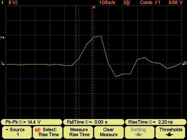
Hi Luc and Sandro,

just a little hint to check out the effect of the software filters and
the bandwidth limiter.

Take a signal with fast rise time and activate QM with the option "Rise
Time". Switching through the filters You will see how the rise time is
affected by the different filters. This is easy to do and shows very
impressive how much bandwidth is cut off by the filters.


Regards Hayo
Rainer W. schrieb:
> Korrektur:
> Es geht doch, allerdings mit mir völlig unverständlichen Zeitlimits.
> Solange die Summe der beiden Werte für die Länge des
> Pulstriggerfensters in dem gezeigten Fall gerade noch unterhalb von
> 287µs liegt, kriegt die Triggerfunktion den genau genommen 192µs langen
> Puls zu fassen. Es ist egal, ob man z.B. (<100, >187), (<140, >147) oder
> gar (>187, <100) einstellt.
> Einen komischen "Hystereseeffekt" gibt es, wenn man den ">"-Wert in der
> Nähe der Pulsdauer variiert, d.h. z.B. <50µs fest eingestellt hat und
> dann

Hallo Rainer,

ich konnte dies eben noch mal mit dem Probe Comp Signal nachvollziehen.
Das schau ich mir nochmal an! Da läßt sich sicher etwas machen.

Gruß Jürgen
Hi Hayo and guys all!

@Hayo
Yes, that is what I did and it is because I say the better choise is to
disable any filter when trying to evaluate the DSO's bandwidth.
In fact it is very simple to make the test, because stopping the DSO
then it is easy to view how filters act by changing the filters setup.
Hayo, thank You very much for your suggestion!

Vielen Dank!!!!!!!

Mit freundlichen Grüßen,

Luc
Schönen guten Abend,

habe jetzt ja das W2022 von Helmut auf dem Schreibtisch und wollte jetzt
das Update auf W2022A machen leider ist die Datei EPC16_W2022A.jcc nicht
mehr unter dem angegebenen Link zu bekommen. Hat einer von euch die
Datei noch auf dem Rechner?

Hoffe ihr könnt hier helfen.

Jan
Ich weiß nicht ob es das ist was Du suchst?

Gruß Hayo
Hallo,

Ich habe damals auch mal eine Wittig W2024 gekauft, aber bis jetzt nich
zu viel Zeit gehabt die auch zu gebrauchen.
Ich habe nun mal herumgeschaut, und gesehen das es bessere Software und
Hardware gibt.
Jetzt wollte ich gerne die Huckepack Platinen einbauen, aber konnte nich
finden ob die irgentwo zu kaufen sind.
Also die frage, kan ich die Platinen irgendwo kaufen, brauchen nicht
bestuckt zu sein, das kann ich mir selber machen.
Wann noch Firmware anderungen notig sind dafur, werde ich mich damit
auch gerne beschaftigen.

Grusse,

Gertjan.
(Niederlande, also entschuldige mein schlechtes Deutch.)
So, hab bis eben an der neuen Version gearbeitet. Das neue Feature wird
Euch gefallen.

Jetzt muß ich den Koffer packen und bin dann erstmal eine Woche auf
Sardinien.

Bis dann

Hayo
das ist GEMEIN , schon wieder anfuettern und
dann abhauen :P

wuensch dir einen schoenen Urlaub und bring mir
was schoenes mit ....


vlG
Charly
Hi,

schöne Grüße von Sardinien. Glücklicherweise gibts hier nen Hotspot, so
dass ich hier nicht ganz abgeschnitten bin.

Das neue Feature - was es ist wird noch nicht verraten, muß erstmal
sehen ob es funktioniert - ist etwas umfangreicher. Wenn ich wieder zu
hause bin werde ich noch etwas brauchen um es fertigzustellen.


@Gertjan

Willkommen in der Gemeinde :-)

Für die Unterstützung der Addon-Platine ist Jörg hier der
Ansprechpartner. Also bei Fragen zur Softwareansteuerung einfach direkt
an ihn wenden.

- und Dein Deutsch ist doch wirklich gut!

Gruß Hayo
Hayo W. schrieb:
> schöne Grüße von Sardinien. Glücklicherweise gibts hier nen Hotspot, so
> dass ich hier nicht ganz abgeschnitten bin.

Das hättest du zu Hause einfacher haben können ;-)
Bin gespannt, was du jetzt wieder an neuen Features ausheckst.
Schöne Tage am Mittelmeer.

Gruß
Rainer
Hallo,

unter
http://welecw2000a.sourceforge.net/docs/Hardware/Welec-Huckepack-Settings-ScaleFactors.xls
findet sich unterstützend zur Softwareentwicklung der Huckepackplatine
ein Tabellenkalkulation-Dokument, anhand dessen man die notwendigen
Einstellungen des LMH6518 und der Eingangsspannungsteiler ablesen und
die Software-Skalierungsfaktoren entnehmen kann.
Mit der Huckepackplatine stehen in allen bisherigen Vertikalablenkungen
224 bis 226 LSB zur Verfügung, der ADC ist also deutlich weiter und in
allen Bereichen bis auf ±1LSB gleich ausgesteuert. Damit wird auch das
Rauschen in den 1er und 2er Bereichen um Welten besser und in den 5er
Bereichen auch noch einmal um gute 10% besser.

Zum Vergleich, in den originalen Einstellungen waren es nur 131 LSB in
den 1er und 2er bzw. 204 LSB in den 5er-Bereichen.
Dies konnte durch die feste Verstärkung von G=1.25 des ersten
Verstärkers auf 163 LSB in den 1er und 2er-Bereichen verbessert werden,
was aber immer noch 20% weniger gegenüber den 5er Bereichen ist und
somit das deutlich größere Rauschen erklärt.
Diese einfache Gegenüberstellung zeigt noch einmal in eindrucksvoller
Weise was die Huckepackplatine zu leisten vermag.

Um das in allen bisherigen Vertikalablenkungen auch mal mit Zahlen
nachvollziehen zu können soll das Dokument zur Aufklärung beitragen.

Darüber hinaus besteht mit dem LMH6518 generell die Möglichkeit die
Vertikalablenkung fließend zu gestalten und nicht auf feste
Vertikalablenkungen in 1er, 2er, 5er-Teilung zurückgreifen zu müssen.

branadic
Hallo Branadic,

danke für den Hinweis.

Gruß Hayo
1094 Beiträge sind genug, hier geht es weiter:
Beitrag "Wittig(welec) DSO W20xxA Open Source Firmware (Teil5)"
Jürgen schrieb:
> Rainer W. schrieb:
>> Korrektur:
>> Es geht doch, allerdings mit mir völlig unverständlichen Zeitlimits.
>> Solange die Summe der beiden Werte für die Länge des
>> Pulstriggerfensters in dem gezeigten Fall gerade noch unterhalb von
>> 287µs liegt, kriegt die Triggerfunktion den genau genommen 192µs langen
>> Puls zu fassen. Es ist egal, ob man z.B. (<100, >187), (<140, >147) oder
>> gar (>187, <100) einstellt.
>> Einen komischen "Hystereseeffekt" gibt es, wenn man den ">"-Wert in der
>> Nähe der Pulsdauer variiert, d.h. z.B. <50µs fest eingestellt hat und
>> dann
>
> Hallo Rainer,
>
> ich konnte dies eben noch mal mit dem Probe Comp Signal nachvollziehen.
> Das schau ich mir nochmal an! Da läßt sich sicher etwas machen.
>
> Gruß Jürgen

@Rainer

Ich hab mal wieder einen Blick zurück getan und die Lösung gefunden :-)
Als Anhang mal eine Probe für die Pulse Width Problematik. Du kannst ja
mal den Anhang ausprobieren, ob es so passt. Es fehlen allerdings noch
die gesamten Prüfungen zu den Eingabebereichen in der Firmware.
Gruß Jürgen
@Mods: Bitte hier schließen, wir diskutieren dort weiter:

Beitrag "Wittig(welec) DSO W20xxA Open Source Firmware (Teil5)"