http://pbuchegger.at/download/_BaMICO8.pdf> Zitat händisch move *.pl to cygin/bin
Aber das denke ich nicht
Fazit:
makefile mit z.B lm8-deployer.pl
sind auf einer make_File-Ebene .
##############################
LatticeMico8 Development
Tools User Guide
##############################
------------------------------
Hint: lm8_dev_tools_ug.pdf
GNU-based Compiler Tools
------via-multible -RUN-CASCADE-STAGES----
------PowerTools Force at make tool
Hint: make Makefile
make all
-------------------------------------------
*******************************************
cygwin
gtools ----> PATH
##############################
--------------------------- tree
******************************************
PATH
C:\LatticeMico8\gtools\bin
##############################
Hint:
makefile Home Base ???
*.pl *.pl means Perl Script files like
C:\LatticeMico8\scripts\lm8-deployer.pl
*.pl In same file-Folder as the Makefile resides
-- *.pl File Hosted in ..\scripts\
lm8_linker.ld,
lm8_linker_large.ld,lm8_linker_medium.ld,lm8_linker_small.ld
------------------------------------------------------------------------
-------
Ende 1
MachX0  Control Develop Kit
Later i will use the new MachX02 with [{preengeneerd}] Embed. Stuff
Fast State 10 case State Engine @2 clk Stoke --1Step....
@Lattice Semiconductor Corporation.
Build Digital@+Analog FPGA inside ispPAC 30

Hint: Look in the owm Diamond IDE
 C:\lscc\LatticeMicoSystem\2.0\micosystem\components\gpio\drivers
Hint:
http://www.latticesemi.com/documents/MachXO%20PLDs%20in%20System%20Control%20Designs.pdf
Hint: compile & run your own stuff Projects
http://www.latticesemi.com/documents/LatticeMico8Tutorial.pdf

# ------------------------------------------------------------------
########################################################################
#
------------------------------------------------------------------------
-
rem prom_init.hex" , "menue.hex"
rem prom_init.v
------------------------------------------------------------------------
-
"menue.hex" habe ich mit hex patch gemoddet. siehe Bild
kommt aus ( EBR)? EmbededBlockRam via UART Print Routine.
bingo>
Das ist *.jed File (mit Bin..Stuff Fuse-Map drin. )
########################################################################
#

Hint:
0x2C005 is Opcode seti

Thema(1)
Hint:
Da oben in co.asm ist der ProzessAnschluss# nich wie bei mir.
Den co.asm muss ich also auch noch auf mein spezi. WishBone Modell
modden.

-------ACK:STACK_STUKTUR:-----------------------------------------------
-------
assign wb_ack = {
                   1'b0,              // Device #15 (UNUSED)
                   ebr_ack,           // Device #14 ACK (EBR)?
EmbededBlockRam
                   1'b0,              // Device #13 (UNUSED)
                   sram_ack,          // Device #12 ACK (SRAM)
                   1'b0,              // Device #11 (UNUSED)
                   spi_ack,           // Device #10 ACK (SPI)
                   1'b0,              // Device #9 (UNUSED)
                   lcd_ack,           // Device #8 ACK (LCD)
                   1'b0,              // Device #7 (UNUSED)
                   fan_ack,           // Device #6 ACK (fan)
                   1'b0,              // Device #5 (UNUSED)
                   led_sw_ack,        // Device #4 ACK (LED/Switches)
                   i2c2_ack,          // Device #3 ACK (PM I2C)
                   i2c_ack,           // Device #2 ACK (I2C)
                   timer_ack,         // Device #1 (TIMER)
           /*FU''#01*/
                   uart_ack           // Device #0 ACK (UART)
           /*ProzessAnschluss_nummer FU-UART-AT'BASE_00*/
                   };
########################################################################
######

UART ProzessAnschluss# ist nicht 0 sondern

Der Lattice MachXO WishBoneBus ist so einfach wie telefonieren.
also File co.asm analysieren.
Fazit:
Prozess: Register Rules. and Procedure Steps
+++++++++++++++++++++++++++
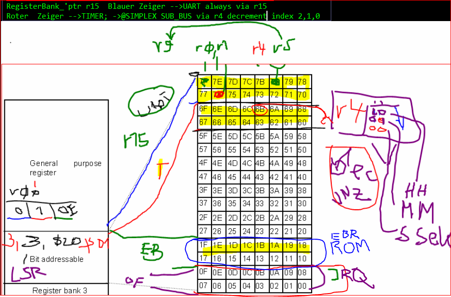
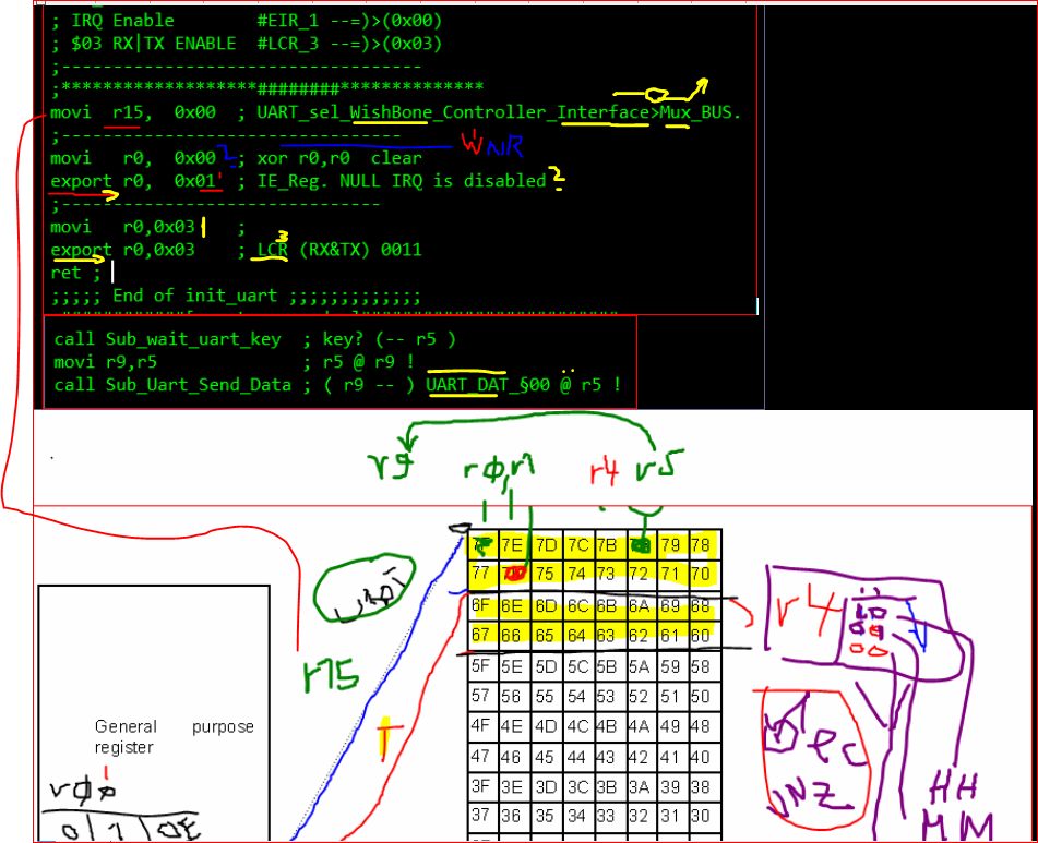
Reg R15 auf Uart_0 also erst mal in meinem "Daten_Modell"  Null
eintragen
................
................

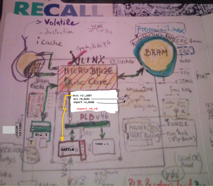
  // movi   r15, TIMER_1
  // export r0, 0x00  ;; issue a 'write' to latch the current time value
  // import r4, 0x02  ;; wahl case hour byte of latched time value
  // .... call wait_for_uart_txrdy
   via r4 import kommt der StundenWert der als Addr_select 0x02 hat
raus.
   >bigo
   nun noch das spezielle r4 Register als Param_werte auf ascii_BCD
modden
   und an den UART mit respective des Timings(wait_for_uart_txrdy) ect.
rausgeben.
   >Bingo.


########################################################################
#
Holger erster IRQ PseudoCode mit Eckdaten
## ResetMode> Mico8 PC =00000
org 00 ## store prog_conter absolut  jmp start_m
b startup_1 # jump ZILOG EZ8 ENCORE ???
##############################
###############################
org 02 ## vector irq trap
int_handler:
nop
nop
nop
nop
reti ## return from 'IRQ_?
#####################################
##
###
####
##----------------------------------
org 38 # like the ZILOG EZ8 ENCORE
startup_1: # Label_1
 seti # first set the program to be able to receive interrupt
      # and push
nop
nop
  if (irq_flg) ??
  clear irq_flg ;
nop
nop
b start_main_2 ## absolut JUMP
 ## free space ROM


###################################
org 100
start_main_2: # main_2 loop
    Call App_Run_forever ## Call SubRoutine
b start_main_2 # JMP back to start_main_2
org 120
##################################
App_Run_forever:
  nop
  nop
ret  ## Return from Sub
##########################################
To do:
Param mystic secret optons for Lattice MachX0 Embed MCU
Check CallStack SratchPadMem
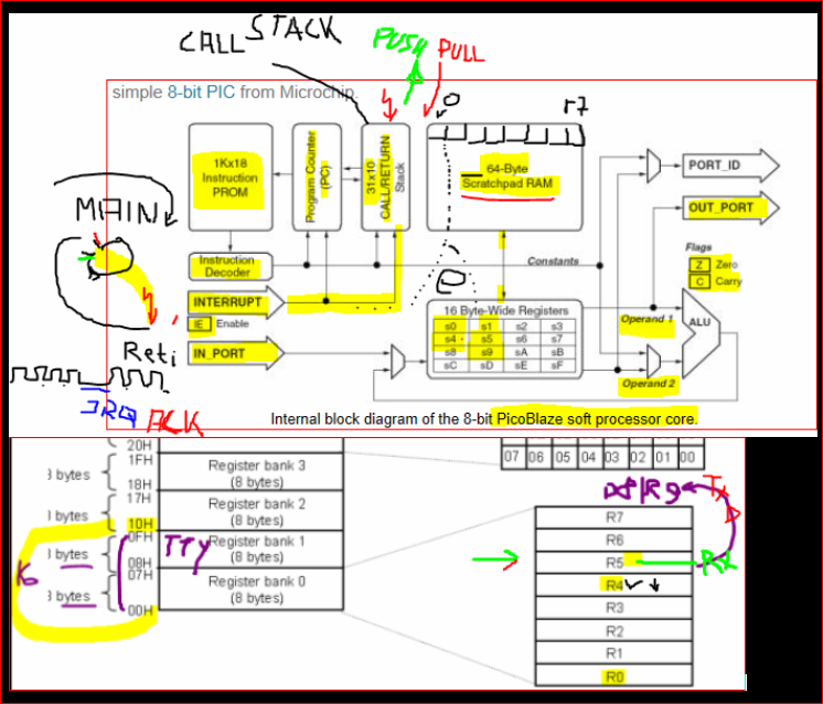
IRQ Handling PUSH regs POP Regs like
80C535 Keil ICC Compiler
Das ist was gutes für den FPGA CPU (Synthesized). USER
######################################################
Hint:
"Build from sratch via Bus Manager"
http://www.origin.xilinx.com/csi/training/embedded-design-with-the-xilinx-embedded-developer-kit.htm

So ist das im Xilinx MicroBlaze abgeleitet.
[code]
#include "xparameters.h"
#include "xiomodule.h"
int main()
{u32 data;
XIOModule gpi1;
volatile int i = 0; // wegen data Cache ???
int g = 0;
data = XIOModule_Initialize(&gpi1, XPAR_IOMODULE_0_DEVICE_ID);
data = XIOModule_Start(&gpi1);

xil_printf("-- Start of the Program --\r\n");
while (1)
{
data = XIOModule_DiscreteRead(&gpi1, 1);
XIOModule_DiscreteWrite(&gpi1, 1, data);
for (i=0; i<10000000; i++);
g = g+1;
xil_printf("-- run: %d --\r\n", g);
}
return 0;
}
[\code]
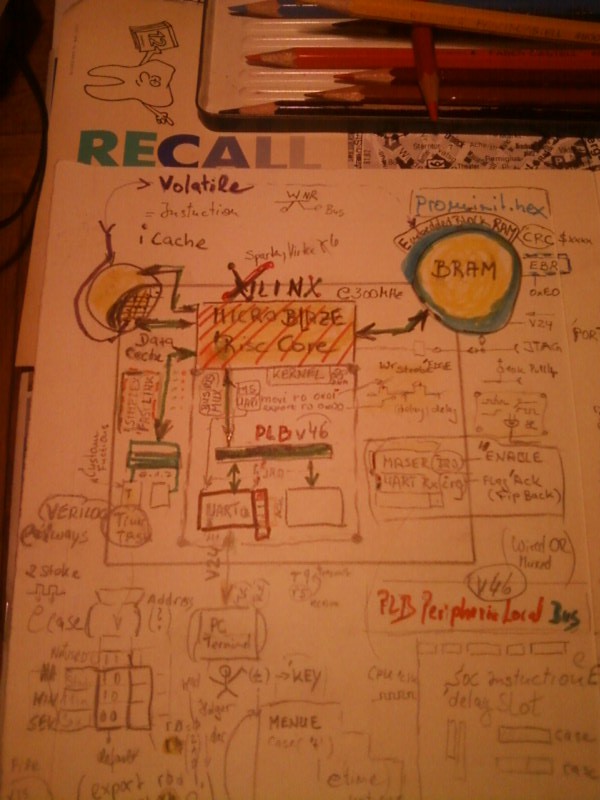
; HOLGER think FIXED ADDRES MAPPING UART 0x00,TIMER 0x10 .SPI. EBR
;;;;;;;;;;;;;;;;;;;;;;;;;;;;;;;;;;;;;;;;;;;;;;
;;;;;;;; *** Utility Functions *** ;;;;;;;;;;;
;;;;;;;;;;;;;;;;;;;;;;;;;;;;;;;;;;;;;;;;;;;;;;
; The "IoReadWord" and "IoWriteWord" are
; used to read/write the IO Bus.
; "XIOModule_DiscreteRead" and "XIOModule_DiscreteWrite"
; used in SIMPLEX FAST LINK  as a local_Bus to the USER
; Custom Verilog_Sub_Modules as eg: uptime_wb.v defined
[code]
init_uart:
; : step_0
  movi r15, UART ; IoWriteWord_IO PLB_periperal_local_Bus_sect Version
(v46).
; : step_1
  movi r0, 0x00  ; 'IER rx_tx_Interrupt ???
  export r0, REG_UART_IER ; !XIOModule_DiscreteWrite
; : step_2
  movi r0, 0x03  ; LCR rx+tx enable ???
  export r0, REG_UART_LCR ; !XIOModule_DiscreteWrite
; : step_3 Return from Subroutine ret opcode
  ret

[\code]
########################################################################
#######

[code]
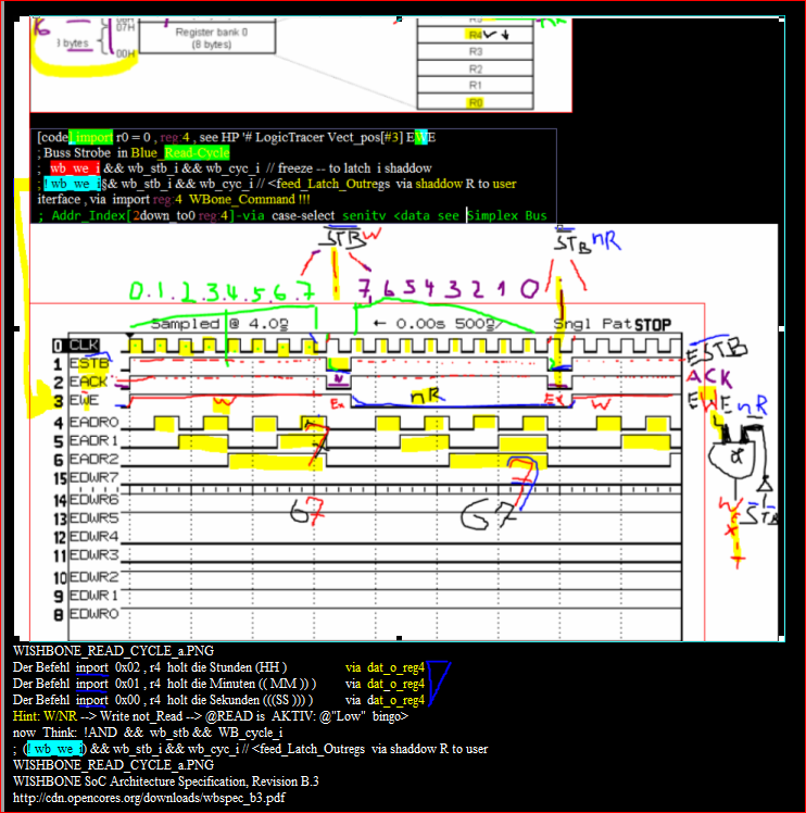
; Hint: "WNR" means W-Rite NOT Read ___>___ issue a
W-##Strobe-Bus-trigger event

; r4 runs via command "import r4,0x02"
;  ... 02,01,00 as via a address_index on FAST SIPLEX BUS
;      HH,MM,SS @R4
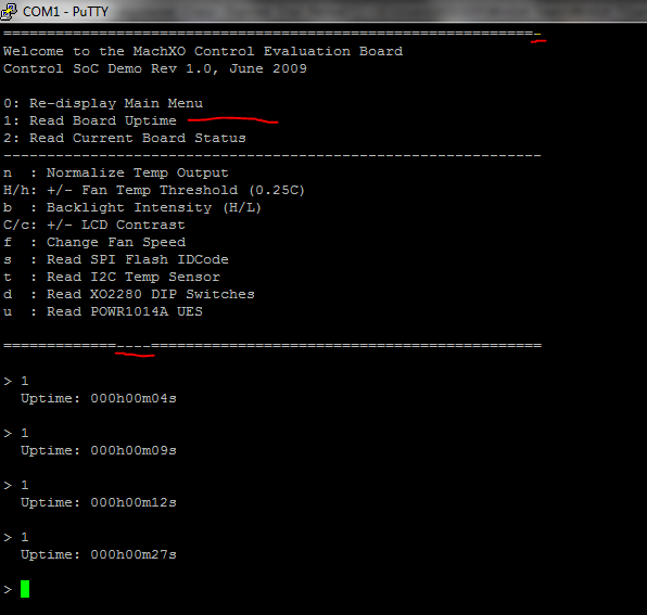
read_uptime:
 ;##################################################################
  movi r15, TIMER  ; PLB (v46) select (trigger--export r0,0x00)
  export r0, 0x00  ;; issue a 'read_$00' to latch the current time value
  import r4, 0x02  ;;; hour byte of latched time value
; ##################################################################
......

 call send_uart_data
;##################################################################
  movi r15, TIMER   ;  PLB (v46) select ()
  import r4, 0x01  ;;; minute byte of time of latched time value
 ;##################################################################
  call int2asc10   ; takes r4 and converts to BCD in r8,r7,r6
  mov r9, r7
  call send_uart_data
  mov r9, r6
  call send_uart_data
  movi r9, 'm'
  call send_uart_data
  ;##################################################################
  movi r15, TIMER   ;  PLB (v46) select ()
  import r4, 0x00  ;;; seconds byte of time of latched time value
 ;##################################################################
  call int2asc10   ; takes r4 and converts to BCD in r8,r7,r6
  mov r9, r7
  call send_uart_data
  mov r9, r6
  call send_uart_data
  movi r9, 's'
  call send_uart_data
  setz ; ????? SettZero what is that
  ret  ; Return from Subroutine
;************{ENDE UPTIME_PROC:(01)]***************************

[\code]


; idcode now in r4
; import as a Fetch and export as a Store, move r0 as a WNR
; Voacabulay: FORTH  Language Parameter Stack
r15********************r4,***,r0
; First store a UART_TTY_0 in reg#15
;
import r4, 0x01 ;;; minute byte of time of latched time value
10
11
movi r15, TIMER ; PLB (v46) select ()
12
import r4, 0x00 ;;; Sekunde byte of time of latched time value
Fazit in Reg: "r4" steht die Address z.B (0x02,0x01,0x00)
 mit dem Befehl "import r4, 00" ist die Sekunde in Register r4 drin.
 Bingo>.
 Danach kann der Inhalt von r4 als 8Bit Wert convertiert zu BCD Routine.
 Danach kommt der Sekunden.Wert an der UART-Schnittstelle raus.
Bingo>.
// Switch Debounce Module
// use your system clock for the clock input
// to produce a synchronous, debounced output
module debounce (reset, clock, noisy, clean);
   parameter DELAY = 270000;   // .01 sec with a 27Mhz clock
   input reset, clock, noisy;
   output clean;

   reg [18:0] count;
   reg new, clean;

   always @(posedge clock or posedge reset)
     if (reset)
       begin
    count <= 0;
    new <= noisy;
    clean <= noisy;
       end
     else if (noisy != new)
       begin
    new <= noisy;
    count <= 0;
       end
     else if (count == DELAY)
       clean <= new;
     else
       count <= count+1;

endmodule
///* Strategie damit das auch bei  2 modulen via
Veriog geht:

Project main_prj.xx
Altera Design main_top.v = Verilog File
module inside VERILOG File is a module main_t_top_1
Hint:
Diamond Tool make a Top Module.
via *.lpf File --like *.ucf in Xilinx
-------------------------------------------
http://www.youtube.com/watch?v=If4iiz4I8Vk
KEY[0]
KEY[1]
------- Create> Vector NODES ----------------------
Konduction ueber Bus Bundel.
Nios aufsetzen.
Beitrag "NiosII Manuell aufsetzen"
Gruss Holger
Diamond Reveal Hardware Debugger
https://www.youtube.com/watch?v=OXxxLRRQmQ4&list=UU5Vv9B2edWD5x57B7mvUDXg&index=20
Damit werde ich mich noch befassen.


Hiracical Browser habe ich bei Lattice Diamond,
Source of  signal map, Load of signal .
Der findet somit das Signal via Browse go to Source Code.
Aber das Code Patata Tool bringt da noch mehr.
Ähnlich wie das Sigasi Tool.

Vielleicht wäre das HDL Code Analyse
Tool Kit eine Option  für Dich?

Gruss Holger.