and must only be used when no other devices are connected on the bus. In addition, spikes on the I C-bus lines must be avoided because of the reduced spike suppression. 8.1.4.12 MFRC522 at lower speed modes 2 MFRC522 is fully downward-compatible and can be connected to an F/S mode I C-bus system. The
I’m delivering the package. That’s what I do. I’m a package-delivery guy.” “That’s one way to look at it. Another way is that both you and the package got here at the same time. And that both of you were necessary. I say the package delivered you.” There was a twisted logic to that interpretation, but
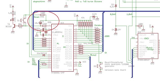
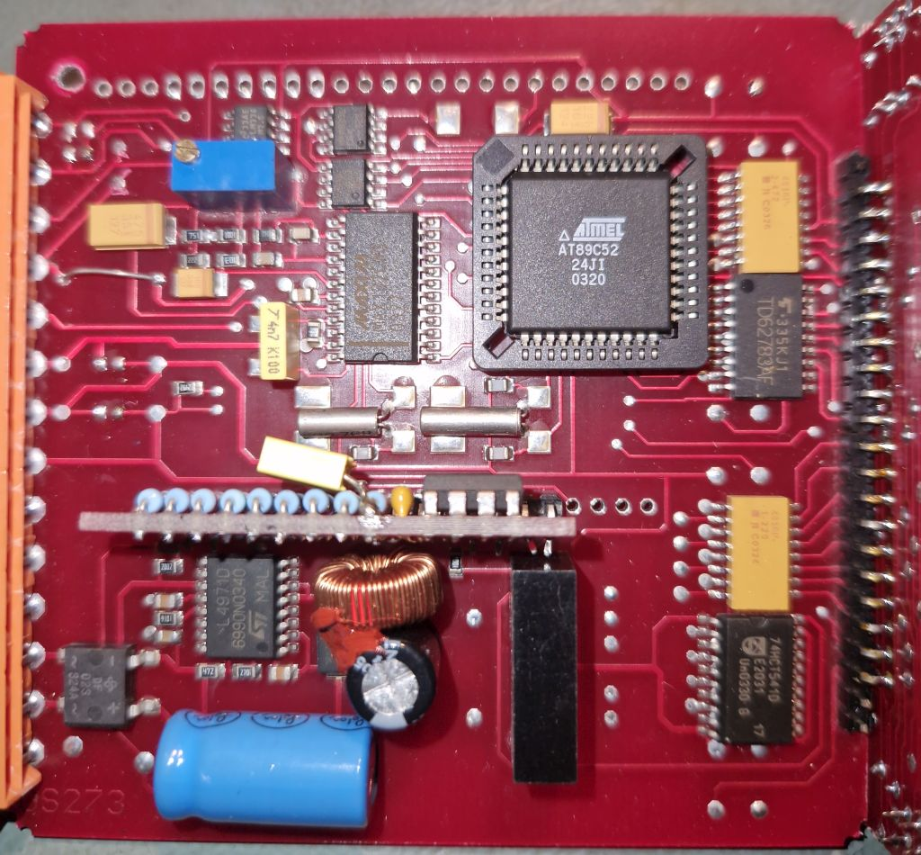
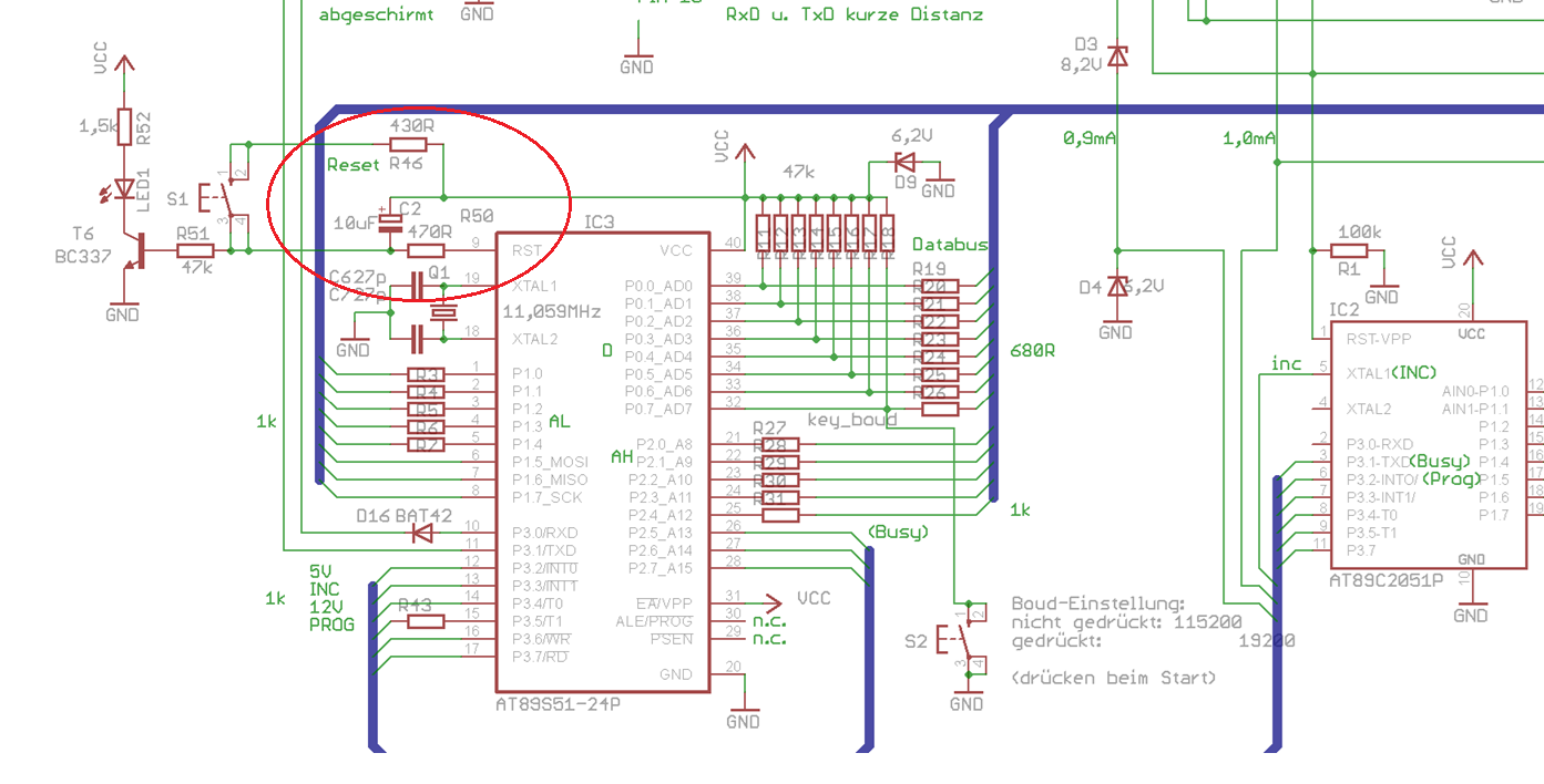
@nepomuk Es ist ein AT89S52 auf der Hauptplatine @wolf17 Wieso mechanisch? 2 Motoren werden mit EINEM Positioner aktuell gesteueert. Es soll ein zweiter Positioner zum ersten synchron laufen. Dabei müssten beide Geräte
dem Leser viel Sucherei ersparen, also z.B. Robert F. schrieb im Beitrag #7995359: > Es ist ein AT89S52 auf der Hauptplatine Robert F. schrieb im Beitrag #7995359: Und bitte bring es auf den Punkt. Wenn du in einem längeren Beitrag auf sieben Leute eingehst, wäre es deutlich übersichtlicher,
in the graphs on the previous page. where: A, B, C, D, A , B , C and D are constant values Example: at 0 °C, assume X = 5 %, Y = 0.89 % and 1 1 1 1 TCR = 5.08 %/K (see table ), then: depending on the material concerned; see table below. 5 0.89 R
. operates at low temperatures (−25°C to −40°C), both the value and ESR of the capacitor will vary considerably. The GRM31CR71C106KAC7 (10 mF, 16 V, X7R, 1206) capacitor manufacturer’s data sheet usually provides
Abgleich möglich ist, es gibt keine Einzelraumregelung. Ich stelle also das System so ein, dass Raum 1 22°C hat, Raum 2 23 und Raum 3 nur 20C. Das ist dann fix. Will man die Temperatur anpassen, macht man das dann über die Heizkurve für alle Räume gleich oder man muss den thermischen Abgleich anpassen.
Wasser aus > der Dusche kommt. Da habe ich schon seit Jahrzehnten eine einfache Steuerung mit AT89C2051 vorgesehen. 1 x drücken: 10 Minuten Betrieb; 3 x 1 h; 4 x 2 h und 5 x wieder ausschalten. Bei den längeren Perioden wird sie alle 10 Minuten für 1 Minute eingeschaltet. Das funktioniert im Sommer
Analog1.8VPower -0.3 1.95 V IOV Input/Output Voltage -0.5 5.5 V TSTG Storage Temperature Range -65 +150 °C T Ambient Temperature 0 +70 °C A LT Lead Temperature - +260 °C (TL, soldering, 10 sec.). 10.2 Operating Conditions Symbol Parameter Min. Typ. Max. Unit Conditions DVDD33 Digital3.3VPower 3.135 - 3.465 V - DVDD18 Digital1.8VPower 1.71 - 1.89 V - AVDD33 Analog3.3VPower 3.135 - 3.465 V - AVDD18 Analog1.8VPower 1.71 - 1.89 V - PD 100BASE-TX - 107 - mA 1.8V only (Power - 54 - mA 3.3V only Dissipation) 10BASE-TX - 57 - mA TX idle, 1.8V only -
vary depending on operating environment and formatting. † Seagate does not recommend operating at sustained case temperatures above 60°C. Operating at higher temperatures will reduce useful life of the product. 2.1 Formatted Capacity Model Formatted Capacity (1) Guaranteed Sectors Bytes per Sector
15: Environmental characteristics Capabilities Description Atmospherics Temperature Operating –10_ C to +50_ C, Class 5 Nonoperating(storage) –51_ C to +71_ C. Class 3 Humidity To 95% relative humidity at or below +55_ C Altitude Operating To 15,000 feet (4572 meters) Maximum operating temperature to
Register_48 data 0x48 Register_49 data 0x49 Register_4A data 0x4A Register_4B data 0x4B Register_4C data 0x4C Register_4D data 0x4D Register_4E data 0x4E Register_4F data 0x4F Register_50 data 0x50 Register_51 data 0x51 Register_52 data 0x52 Register_53 data 0x53 Register_54 data 0x54 Register_55 data
Hi! Benötigt wird DIL40. Ich hätte sonst auch AT89S... als DIL da. Roger P. schrieb im Beitrag #7981985: > Will die wegwerfen.... Ach so. :o) Versuch es doch hier im Markt! Gruß Jobst
Videotextdecoder ist. Das wird aber spätestens beim verifizieren auffliegen. Ich teste hier mit AT89S52. Gruß Jobst
Testing and measurement techniques. Section 13: Harmonics, interharmonic including mains signalling at A. C. Power port, Immunity tests. r630005d - 16.10.aa – Dieter Helmich Seite 83 von 122 5.9 Checking the level of supplied power If the user wishes to reactivate the booster, this can be done. The booster
event pending flag, set by H/W at INT2 pin’s falling INT2IF 0C.2 R - edge W 0 write 0: clear this flag; write 1: no action R - INT1 (PA1) interrupt event pending flag, set by H/W at INT1 pin’s INT1IF 0C.1 falling/rising edge W 0 write 0: clear this flag; write 1: no action INT0 (PA3) interrupt event pending flag, set by H/W at INT0 pin’s INT0IF 0C.0 R - falling/rising edge W 0 write 0: clear this flag; write 1: no action INTIE1 (0Dh) Function related to: Interrupt Enable All port pin change wakeup interrupt enable PCIE 0D.6
event pending flag, set by H/W while WKT time out WKTIF 0C.3 W 0 write 0: clear this flag; write 1: no action R - INT2 (PA7 or PB5) interrupt event pending flag, set by H/W at INT2 INT2IF 0C.2 pin’s falling edge W 0 write 0: clear this flag; write 1: no action INT1 (PA1 or PB1) interrupt event pending flag, set by H/W at INT1 INT1IF 0C.1 R - pin’s falling/rising edge W 0 write 0: clear this flag; write 1: no action R - INT0 (PA3 or PB2) interrupt event pending flag, set by H/W at INT0 INT0IF 0C.0 pin’s falling/rising
enters 2·C 1∆t·V (c = 0)+I (c = 0) at position 1 of the right-hand side vector. Note thct I (t = 0) is zero because the voltage V1is applied at t = 0. Finally, the complete matrix equation writes as follows.
H 4 6 n Equivalent = 0 4 C 1 = C2= 2.52 pF circuit 2 C L COUT= 144 pF C4= 68 pF L 3= 9.2 nH L 1= 4.45 nH L2= 3.4 nH Ω F 7 RFO_HP F n . or RFO_LP 3 . 1 . C 3 C’ 3 = 5 5 U 1 C O C R C3new value For example, if C3 = 0.8 pF and C'
THERMISTOR RESISTANCE VALUES Tc Resistance Value [kW] Tc Resistance Value [kW] Tc Resistance Value [kW] [5C] Min Typ Max [5C] Min Typ Max [5C] Min Typ Max −40 4130.00 4251.00 4612.34 16 152.51 154.60 156.96 72 13.69 14.10 14.52 −39 3851.00 3962.00 4290.13 17 145.20 147.20 149.28 73 13.19 13.60 14.00 −38 18
playback of a track Play track "0001" in the specified folder in a folder that supports 7E FF 06 14 00 C0 01 FE 26 EF 7E FF 06 14 00 C0 01 EF “12” 3000 tracks Play track "0255" in the specified folder 7E FF 06 14 00 C0 FF FD 28 EF 7E FF 06 14 00 C0 FF EF “12” Play track "1999" in the specified folder 7E
Limit 10K 0 R173 . C181 C185 C223 CMOS Digital Integrated Circuit Hiccup D 10K1 2 + C222 Shutdown N R52 R175 83 3 7 no_use no_use no_use no_use D 10K R3 3 R +3.3H1 C182 C186 C224 IC/CB/XL:1-19 10KX4 R53 I S O DGND ST EN
polynomial of H(s). The result is _ -(RC+ L/R)-:k. [(RC+ L/R)- 8LC]1/2 P1.2 -- - - - - - - - 2 - L - C - - - - - - - (2.4-6) If we allow the source and load resistances to be equal at I n and assign values of L = v'2 henry (H) and C = v'2 farad (F), the poles occur at p= (l -:kj.l)/v'2. We will examine
frmMain.lbAdrFax=F&ax frmMain.lbAdrINet=&Internet Link frmMain.lbAdrMail=&E-Mail frmMain.lbAdrKundNr=C&ustomer No. frmMain.lbAdrUsId=&VAT ID frmMain.spInternetHint=Open Web Browser frmMain.lbAdrLand=C&ountry frmMain.spANewHint=New Entry frmMain.spACopyHint=Copy Data frmMain.spASaveHint=Save Data frmMain.spAAbortHint
characters CPT8 = CPT8 + 1 number characters charactererror un e3 characters sil nce YES error on at least NO 1 frame character YES length NO < 3 bytes YES NO CRC incorrect C P T 2 = C P T 2 + 1 C P T1 = C P T 1 + 1 YES NO slave number = 0 or YES slave NO slave number = my slave CPnumber 04 + 1 number
is shown inFigure 7.34. In short,this technique allowsthe otherwise long table lookup ROM with 2“*”*C storage locations to be replaced by two smaller ROMs having storage sizes of 2**# and 2**“ locations. In the case where A = B =C=4 and D = 12 bits, the noncompressed table would require 45056 bits (11
95 94 93 92 91 90 89 88 87 86 85 84 83 82 81 8079 78 77 76 75 74 73 DS D S 5 m 3 BUS0 2 3 T I D DIR_INT1 10K 1 1 4 SP_PROT o BUS0 1 109 U U T C C C W E N N O N N N S ST C R C L _ D T S C A N T N O S S T 72 R r CD CCE 1 110
Eckhard T. schrieb im Beitrag #7935422: > Handelt es sich um einen AT89C52 oder eine der AT89C52R.. Versionen? > Letztere lassen sich ggf. leicht seriell programmieren und auslesen. Du meinst wohl eher den AT89S52. Einen AT89C52R* gibt es nicht. Und der AT89C51RC
Peter D. schrieb im Beitrag #7935448: > Eckhard T. schrieb: >> Handelt es sich um einen AT89C52 oder eine der AT89C52R.. Versionen? >> Letztere lassen sich ggf. leicht seriell programmieren und auslesen. > > Du meinst wohl eher den AT89S52. > Einen AT89C52R* gibt es nicht. Und der AT89C51RC
load. The following is a typical example: Name Fanout Delay (ns) Site Resource REG_DEL --- 0.285 R89C27C.CLK to R89C27C.Q0 U_core/SLICE_29896 (from tel_clk_155) ROUTE 3 4.914 R89C27C.Q0 to R91C45D.D1 U_core/rx_tu_mode_2 CTOF_DEL --- 0.180 R91C45D.D1 to R91C45D.F1 U_core/ddwr_stm8/SLICE_36645 ROUTE 1
Ist von 2002 https://github.com/avrdudes/avr-libc/commit/7aecd309ad6681c9ae1281cc931fec4b52dbc820#diff-8c72afd145ee38584ffc03366c04a257f2f626c4cf17626768edf6cb2cbd0578
Glas Wein noch unterhalten. Diese Zeiten sind leider lange vorbei. Ich habe noch das erste STK für AT90S1200/2313/8515. Da saß ein AT89C2051 als Programmer drauf. Dann gab es das STK300 mit ATmega103, leider ohne Programmer-µC. Das mußte man an den LPT-Port anschließen, habe ich daher nie benutzt.
dekompilieren lassen: https://github.com/Daniel-Abrecht/dpa-utils/blob/ba2e0cc211221e0565a09bda88234648fa0182c5/src/main/example/utf8.c https://dogbolt.org/?id=d365debe-8058-40a0-aeb6-09dfa4ef52d4 Das meiste wurde natürlich schon weg optimiert. Die verwendeten struct typen, die inline Funktionen, usw. von
Geräte haben oft Zeitbedingungen, die eingehalten werden müssen. Z.B. wird ein Gerät mit einem AT89C2051 nicht mehr laufen, wenn man es mit einem AT89LP2052 ausrüstet. Grund ist einfach, daß der LP die Instruktionen viel schneller ausführt und damit alle Abläufe zeitlich nicht mehr stimmen. Das
Layouts 33 Circuit Diagrams 39 1 Specification General specifications apply for the temperature range 5°C to 40°C. Accuracy specifications apply for the temperature range 18°C to 28°C after 1 hour warm-up with no load and calibration at 23°C. Typical specifications are determined by design and are not guaranteed
0777007 (Fig. 21 /A) • Brushbar – 0777017 (Fig. 21 /B) out the filters under running water (max. 40 °C). 7 Leave the filters dry for at least 24 hours before • Pre-motor filter – 0777001 (Fig. 21 /C) putting them back in the appliance. • Wall mount – 0777006 (Fig. 21 /D) • Filter set (separator + filter
Layout des CG-3000 nachgezeichnet, damit ich verstehen kann, was da drin was macht. Das ist am Ende ein AT89C52 plus 82C55, ein bissel was an diskretem Krimskrams (Analogzeug zum Messen von Stehwellenverhältnis etc.) sowie ein Sack voller Relais, der die Spulen und Kondensatoren umschaltet. Dafür nennt mir KiCads Statistik 399 THT-Pins und 301 SMD-Pads. Zum Aufpeppen würde ich dann 89C52 und 8255 durch ein Aufsteckboard mit ATmega1281 ersetzen. Das liegt mit reichlich 300 Pins/Pads schon wieder halbwegs im Rahmen dessen, was die kostenlose Diptrace-Version macht. Eins meiner größeren
0018 ??_AT89C51RD2_ NUMBER 001B ??_AT89C51_ NUMBER 0015 ??_AT89C52_ NUMBER 0016 ??_AT89C55WD_ NUMBER 0017 ??_AT89LP2052_ NUMBER 0001 ??_AT89LP213_ NUMBER 0003 ??_AT89LP214_ NUMBER 0004 ??_AT89LP216_ NUMBER 0005
Axel S. schrieb im Beitrag #7919326: > Aber damals gab es halt auch keine µC. Zumindest keine, die man dafür > hätte ver(sch)wenden wollen. Ich habe früher kleinere Logikschaltungen mit dem AT89C2051 aufgebaut. Man brauchte zwar noch ein Programmiergerät, aber keine Löschlampe
COM-Port gechrieben, allerdings habe ich hier gleich die mit mehr Speicherkapazität präferiert, also AT89C52 und AT89C4051, weil es trotz Assembler ziemlich schnell knapp werden kann – einige von den ICs (neu) liegen bei mir noch als Erinnerung herum. Das war aber natürlich alles 1-2 Dekaden später als
maximum) gap reference to assure output voltage accuracy to • Temperature range: within ±1%. – LM1117: 0°C to +125°C A minimum of 10-µF tantalum capacitor is required – LM1117I: –40°C to +125°C at the output to improve the transient response and stability. 2 Applications Package Information • AC drive power
Advanced Information-Confidential P/N-T100-Rev02 Copyright by Terawins, Inc. 2 Theory of Operations 2.1 I2C Command Protocol Before your tester writes IC commands to T100, slave address must be set at 50h. The timing sequence can be shown as below. After 4 cycles, the tester can get started IIC commands. SDA
_____ 100 0.8/__ At bottom. Solvent used in paint. 1. Detectable odor at (C 10 16 odor. ache, dizziness, nau- low concentrations. sea, irritation of the 2. Combustible gas kidneys. indicator. Xylene Colorless, Flammable
bit will be set. If ITEVTEN bit (in R16_I2C_CTRL2) is set, an interrupt will be generated. At this time, it is required to read the status register1 (R16_I2C_STAR1), write slave address to the data register, SB bit will be automatically cleared
regulation; the value of RF max determines the maximum frequency the half-bridge will be operated at when the phototransistor is fully saturated; 3. An R-C series circuit (C SS + R SS ) connected between the pin and ground that enables to set up a frequency shift at start-up (see Chapter 7.3: Soft-start

 Bild
Bild
 Bild
Bild