spikes on the I C-bus lines must be avoided because of the reduced spike suppression. 8.1.4.12 MFRC522 at lower speed modes 2 MFRC522 is fully downward-compatible and can be connected to an F/S mode I C-bus system. The device stays in F/S mode and communicates at F/S mode speeds because a master code is
Timinig generator OSC2 S e a e n a a o at LCD drive power supply circuit c Common COM1 to r driver COM176 u t V V C C V B V C C C C V V V V V V i c 1 1 O A i 2 2 E E R R S C M C U 1 + - T S 2 + - + - F F H H L T o o C o o L
necessary?” he asked. “Look,” I said, “I’m holding the package and I’m walking 9 God’s Debris with it. That’s delivering. I’m delivering the package. That’s what I do. I’m a package-delivery guy.” “That’s one way to look at it. Another way is that both you and the package got here at the
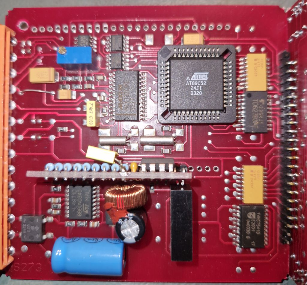
@nepomuk Es ist ein AT89S52 auf der Hauptplatine @wolf17 Wieso mechanisch? 2 Motoren werden mit EINEM Positioner aktuell gesteueert. Es soll ein zweiter Positioner zum ersten synchron laufen. Dabei müssten beide Geräte
dem Leser viel Sucherei ersparen, also z.B. Robert F. schrieb im Beitrag #7995359: > Es ist ein AT89S52 auf der Hauptplatine Robert F. schrieb im Beitrag #7995359: Und bitte bring es auf den Punkt. Wenn du in einem längeren Beitrag auf sieben Leute eingehst, wäre es deutlich übersichtlicher,
in the graphs on the previous page. where: A, B, C, D, A , B , C and D are constant values Example: at 0 °C, assume X = 5 %, Y = 0.89 % and 1 1 1 1 TCR = 5.08 %/K (see table ), then: depending on the material concerned; see table below. 5 0.89 R ref.s the resistance value at a reference temperature
SOLDERING REFLOW (Note 2) Lead Temperature Soldering T °C SLD Reflow (SMD styles only), Leaded, 60−150 s above 183, 30 s max at peak − 240 Reflow (SMD styles only), Lead Free, 60−150 s above 217, 40 s max at peak − 265 Wave Solder (through hole styles only), 12 sec max − 310 2. Per IPC/JEDEC J−STD−020C.
Kauf dir ein Balkonkraftwerk mit Speicher und Inselbetrieb und/oder einer "Notstrom-Steckdose". Gibt's doch inzwischen alles preiswert von zig Anbietern
Wasser aus > der Dusche kommt. Da habe ich schon seit Jahrzehnten eine einfache Steuerung mit AT89C2051 vorgesehen. 1 x drücken: 10 Minuten Betrieb; 3 x 1 h; 4 x 2 h und 5 x wieder ausschalten. Bei den längeren Perioden wird sie alle 10 Minuten für 1 Minute eingeschaltet. Das funktioniert im Sommer
permanently set to 0. 0 = No next page available 1 = Next page available 14 ACK RO Acknowledge 0b The DM8603's auto-negotiation state machine will automatically control this bit in the outgoing FLP bursts and set it at the appropriate time during the auto-negotiation process. Software should not attempt to write
priority, and the next priorities are queue 2, 1, and 0 respectively. 4 TOS_PRI PE0,RW Priority ToS over VLAN If an IP packet with VLAN tag, the priority of this packet is decode from ToS field. 3 TOS_OFF PE0,RW ToS Priority Classification Disable The priority information from ToS field of IP packet
0.13W Sleep 0.13W 1. During periods of drive idle, some offline activity may occur according to the S.M.A.R.T. specification, which may increase acoustic and power to operational levels. 2. Standby power is measured at steady state (after 200ms from transition) Seagate BarraCuda Product Manual, Rev.
Resolution Mode 10 Hz to 20 kHz 1 mV High Bandwidth Mode 11.7 Hz to 80 kHz 3 mV Amplitude Accuracy at 120 Hz, High Resolution Generator Normal Mode At +13.9 dBu ±0.1 dB, typically ±0.05 dB –16.1 dBu to +30 dBu ±0.1 dB –34.1 dBu to <–16.1 dBu ±0.15 dB, typically ±0.1 dB –52.1 dBu to <–34.1 dBu ±0.25 dB
0x4D Register_4E data 0x4E Register_4F data 0x4F Register_50 data 0x50 Register_51 data 0x51 Register_52 data 0x52 Register_53 data 0x53 Register_54 data 0x54 Register_55 data 0x55 Register_56 data 0x56 Register_57 data 0x57 Register_58 data 0x58 Register_59 data 0x59 Register_5A data 0x5A Register_5B data
' DB 0x40 ;40 -- '@' DB 0x00 ;00 -- '' DB 0xD2 ;D2 -- '' DB 0x22 ;22 -- '"' DB 0xE5 ;E5 -- '' DB 0x52 ;52 -- 'R' DB 0xB4 ;B4 -- '' DB 0x64 ;64 -- 'd' DB 0x00 ;00 -- '' DB 0x50 ;50 -- 'P' DB 0x02 ;02 -- '' DB 0x05 ;05 -- '' DB 0x52 ;52 -- 'R' DB 0x05 ;05 -- '' DB 0x53 ;53 -- 'S' DB 0x05 ;05 -- '' DB 0x3F
O RS232 debug port 88 PSDAT3 TP_DAT I/OD 10K Pull +3VS 96 VCC +3VA_EC P C 31 GPIO17 N.C O Reserved 89 GPIO50 BATSEL_3S O Battery series. Hi:3S, 111 VCC +3VA_EC P Lo:4S(Unused) 32 GPIO18 PWR_SW# I power button, * 90 GPIO52 CHG_LED_UP# O charger LED 113 GND GND P 34 GPIO19 MAIL_LED# O Mail LED(Unused)
Hi! Benötigt wird DIL40. Ich hätte sonst auch AT89S... als DIL da. Roger P. schrieb im Beitrag #7981985: > Will die wegwerfen.... Ach so. :o) Versuch es doch hier im Markt! Gruß Jobst
Videotextdecoder ist. Das wird aber spätestens beim verifizieren auffliegen. Ich teste hier mit AT89S52. Gruß Jobst
Black vitroceramic glass 3.7.3 Markings on glass In the models for Balay and Lynx there is a label at the top on the right Metal look vitroceramic glass with the complete model without KI printed on it. The other models only have the supplier’s number, at the top on the left, enabling us to find out
will clear this flag 0Ch.2 INT2IF: INT2 pin falling interrupt pending flag This bit is set by H/W at INT2 pin’s falling edge, write 0 to this bit will clear this flag 0Ch.1 INT1IF: INT1 pin falling/rising interrupt pending flag This bit is set by H/W at INT1 pin’s falling/rising edge, write 0 to this
will clear this flag 0Ch.2 INT2IF: INT2 pin falling interrupt pending flag This bit is set by H/W at INT2 pin’s falling edge, write 0 to this bit will clear this flag 0Ch.1 INT1IF: INT1 pin falling/rising interrupt pending flag This bit is set by H/W at INT1 pin’s falling/rising edge, write 0 to this
coefficient Frequency (800 MHz to 8 GHz) Frequency (GHz) m3 m4 Freq = 868.0 MHz -5 Freq = 868.0 MHz dB(S(2,1)) = -8.344 e dB(S(4,3)) = -0.177 Note: At 868 MHz, the impedance is in the center of the chart, with a forward transmission coefficient equal to -0.1 dB for the simulation with S-parameters of real
computer. Communication Standard: 9600 bps Data bits: 1 Checkout: none Flow Control: none Format: $S Ver. Length CMD Feedback Para_MSB Param_LSB Check_MSB Check_LSB $O $S Start byte 0x7E Ver. Version 0xFF by default Length Number of byte from version info to Check_LSB, typically 0x06 (checksum not counted
0 6 Q254 C258 C269 _ O L M M M S _ _ U U A S S M M I D _ S S 0 3 0 3 R 3 3 0 0 3 0 3 0 S 1 0 2 S 1 OUT Output Pin (“L” at Detection, “Hi-Z” at Released) HN4B01JE(TE85L, C V O P N N T T S R288 P P A A P _ 7 1 R 1 R 1 R 1 1 R 1 R 2 5
at s = -1/ RC. The filter has no finite zeros. Substitution of jw for s in Eq. 2.4-1 provides the frequency response. The filter shows no attenuation at dc. As frequency increases, the response immediately
Housing/Variant frmMain.spPGFilterGehVarianteHint=Filter By Housing/Variant frmMain.spBestEingelagert=S frmMain.mn2DDruck=Print 2D Barcode Strings.51= Strings.52= Strings.53= frmBildSize=Picture size frmBildSize.lbTxt=The image is very large and should be reduced in size so that it does not require too
Turnaround delay should be shorter than the Response time-out. Typically the Response time-out is from 1s to several second at 9600 bps; and the Turnaround delay is from 100 ms to 200ms. Frame error consists of : 1) Parity checking applied to each character; 2) Redundancy checking applied to the entire frame
6 10K BUS2 1 1 3 3 0 0 0 0 0 0 C 5 U 3 3 3 3 3 3 3 C HP_MUTE 5 5 4 5 0 BUS1 1 B V R262 2 3 0 3 4 D S D SS DGND 1 108 107 106 105 104 103 102 101 100 99 98 97 96 95 94 93 92 91 90 89 88 87 86 85 84 83 82 81 80 79 78 77 76 75 74 73 DIR_INT1 10K 1 1 5 SP_PROT BUS0 1 BUS0 109 S S B K K K T T T E T T T S
Eckhard T. schrieb im Beitrag #7935422: > Handelt es sich um einen AT89C52 oder eine der AT89C52R.. Versionen? > Letztere lassen sich ggf. leicht seriell programmieren und auslesen. Du meinst wohl eher den AT89S52. Einen AT89C52R* gibt es nicht. Und der AT89C51RC
Peter D. schrieb im Beitrag #7935448: > Eckhard T. schrieb: >> Handelt es sich um einen AT89C52 oder eine der AT89C52R.. Versionen? >> Letztere lassen sich ggf. leicht seriell programmieren und auslesen. > > Du meinst wohl eher den AT89S52. > Einen AT89C52R* gibt es nicht. Und der AT89C51RC
given: a clock period of 20 ns, board clock skew of 1ns, board trace of 8 ns, and the source device’s clock to out spec of 7 ns. This causes the data to arrive at its FPGA data pin at least 4 ns before its 4 Timing Closure Introduction capture clock edge arrives at its FPGA pin – this is the input setup
Glas Wein noch unterhalten. Diese Zeiten sind leider lange vorbei. Ich habe noch das erste STK für AT90S1200/2313/8515. Da saß ein AT89C2051 als Programmer drauf. Dann gab es das STK300 mit ATmega103, leider ohne Programmer-µC. Das mußte man an den LPT-Port anschließen, habe ich daher nie benutzt. Und dann das originale STK500 mit AT90S1200 und AT90S8535. Der AT90S1200 war nur für Firmware-Updates zuständig, da die AVRs alle noch keinen Bootloader unterstützten. Somit konnte man das STK500 auch nicht aussperren.
Dieter S. schrieb im Beitrag #7926029: > - keine Optimierung beim Compiler (GCC) Und wie sieht das Ergebnis bei Optimierung auf Ausführungsgeschwindigkeit aus?
Geräte haben oft Zeitbedingungen, die eingehalten werden müssen. Z.B. wird ein Gerät mit einem AT89C2051 nicht mehr laufen, wenn man es mit einem AT89LP2052 ausrüstet. Grund ist einfach, daß der LP die Instruktionen viel schneller ausführt und damit alle Abläufe zeitlich nicht mehr stimmen. Das
clear. 2. To remove the pcbs, first improve access by unscrewing the front panel: remove the screw(s) securing the front panel bracket(s) to the spacer in the centre of the Power pcb(s) and remove the screws that fix the bottom edge of the front panel to the chassis. The front panel can be tipped forward
držiak k stene po- vacou silou (obr. 10/ 3 ). 3 Pomocou tlačidla valca mocou skrutiek a rozperiek. s kefkami môžete zapnúť a vypnúť valec s kefkami (obr.10 /2 ). 4 Vysávajte. Nabíjanieakumulátora UPOZORNENIE: Ak dôjde k zablokovaniu valca s kefkami, prístroj ! VÝSTRAHA! sa vypne a kontrolka na turbokefe
Layout des CG-3000 nachgezeichnet, damit ich verstehen kann, was da drin was macht. Das ist am Ende ein AT89C52 plus 82C55, ein bissel was an diskretem Krimskrams (Analogzeug zum Messen von Stehwellenverhältnis etc.) sowie ein Sack voller Relais, der die Spulen und Kondensatoren umschaltet. Dafür nennt mir KiCads Statistik 399 THT-Pins und 301 SMD-Pads. Zum Aufpeppen würde ich dann 89C52 und 8255 durch ein Aufsteckboard mit ATmega1281 ersetzen. Das liegt mit reichlich 300 Pins/Pads schon wieder halbwegs im Rahmen dessen, was die kostenlose Diptrace-Version macht. Eins meiner größeren
??_AT89LP4052_ NUMBER 0002 ??_AT89LP428_ NUMBER 0006 ??_AT89LP52_ NUMBER 0007 ??_AT89LP6440_ NUMBER 0009 ??_AT89LP828_ NUMBER 0008 ??_AT89LS51_ NUMBER 0011 ??_AT89LS52_ NUMBER 0012 ??_AT89S2051_ NUMBER 000A ??_AT89S4051_ NUMBER 000B ??_AT89S51_ NUMBER 000C ??_AT89S52_ NUMBER 000D ??_AT89S53_ NUMBER 000E ??_AT89S8252_ NUMBER 000F ??_AT89S8253_ NUMBER 0010 ??_DEFAULT_ NUMBER 0000 AC BIT D6 ACC DATA E0 B DATA F0
Axel S. schrieb im Beitrag #7919326: > Aber damals gab es halt auch keine µC. Zumindest keine, die man dafür > hätte ver(sch)wenden wollen. Ich habe früher kleinere Logikschaltungen mit dem AT89C2051 aufgebaut
COM-Port gechrieben, allerdings habe ich hier gleich die mit mehr Speicherkapazität präferiert, also AT89C52 und AT89C4051, weil es trotz Assembler ziemlich schnell knapp werden kann – einige von den ICs (neu) liegen bei mir noch als Erinnerung herum. Das war aber natürlich alles 1-2 Dekaden später als
Active Production SOT-223 (DCY) | 4 2000 | LARGE T&R Yes SN Level-1-260C-UNLIM 0 to 125 N03A LM1117S-ADJ/NOPB Active Production DDPAK/ 45 | TUBE ROHS Exempt SN Level-3-245C-168 HR 0 to 125 LM1117S TO-263 (KTT) | 3 ADJ LM1117S-ADJ/NOPB.B Active Production DDPAK/ 45 | TUBE ROHS Exempt SN Level-3-245C-
Copyright by Terawins, Inc. The waveforms shown below illustrate TCON location counting. Each TCON signal’s placement and duration are allowed to program as alike as analog LCD panels require. On the figure 2-2, the pulse placement starts counting at the leading edge of DE. After placement counter meets the
sampling programs (24 sampl3s at a rate of one 200-ml sample per hour, using 10 ft. of /8-in.vinyl suction line Note: Not certified by UL. at a 5-ft. head) Controller Internal 3V Lithium Battery. Isco 340-5000-00 5 years, minimum
data at S4 f . SDOUT / SDIN5 29 I2S data out or SDIN5 (must be sync'd to post SRC rate). Usually used for Microphone ADC Input TEST 32 DI Test mode active high. In normal mode tie this to digital ground. VALID
SCS (interval time of SPI operationTsys*2 nS TCH Time of SCK clock at high level Tsys*0.55 nS TCL Time of SCK clock at low level Tsys*0.55 nS Setup time of MOSI/MISO input before SCK rising TDS edge 8 nS TDH Hold time of MOSI/MISO input before
been switched OFF. Assuming that the time constant of the RC filter is at least ten times the minimum switching frequency f min, the approximate value of R can be found using the empirical equation: S Vs pkx 5 ⋅ 0.8 4 R S = I-----≈-I------≈I------------ Crpkx Crpkx Crpkx where

 Bild
Bild
 Bild
Bild