Moritz Z. schrieb:
> Wenn ich euer Fachgespräch nochmal unterbrechen darf:
> Ersteinmal vielen Dank für die Antworten. Ich habe es mit dem Perl
> Skript versucht, aber er hat gleich am Anfang abgebrochen weil er etwas
> nicht überprüfen konnte.

Stand da etwas von "SerialPort"?

Du brauchst:

Device::SerialPort

(evtl. noch mit Win32 dazu)

> Jetzt bin ich dabei die Firmware mit dem
> Updater drauf zu machen - mit Windows 7 und USB Adapter für RS232
> allerdings nicht besonders empfehlenswert. Dauert 6 Stunden! Wenn das
> Oszi am Schluss noch lebt funk ich nochmal durch.
>
> Nochmals vielen Dank für eure Arbeit!
>
>
> Gruß,
> Moritz

Grüße,

   rowue
@Moritz

Wenn Du vorhast des öfteren mal eine neue Open Source Firmware
draufzuspielen, dann solltest Du noch etwas weiter mit dem Perlskript
rumprobieren.


@Michael

Moment, ich probiere gerade mit den Skalierungen rum, wenn ich was
Passendes habe, dann lade ich das hier hoch, dann könnt Ihr's Euch
selbst machen...   ;-)

Hayo
Angehängte Dateien:
-

DSC00066_s.jpg
34 KB
So.
Writing line 017224 of 022368 :-)
Wie es geklappt hat?
Also:
1. Baudrate im Gerätemanager auf 115200 setzen
2. Adapter ohne Kabel anschließen
3. Die linken zwei Softbuttons gleichzeitig drücken, gedrückt halten,
dann den Flash- oder Ramloader starten und sofort beide Tasten
loslassen.

Nochmal Danke für alles!

Grüße aus dem sonnigen Stuttgart,

Moritz

PS: Danke Michael das du mich Motiviert hast den Vorgang mit dem Updater
abzubrechen!
*edit:*
PPS: Michael hat sich sogar die Mühe gemacht mir eine lange Email mit
der genauen Vorgehensweise und möglichen Fehlern zu schreiben. Ich bin
sprachlos! Tolles Forum!
Michael D. schrieb:
> Die 150k sollen ja nicht so gravierend sein, aber naja...
> der Guido hatte das berechnet, glaube ich.

Nehmen wir den André,
Beitrag "Re: Wittig(welec) DSO W20xxA Open Source Firmware (Teil2)"

und stimmt - ich meinte immer den 150K - bloss, da mir die
Amplitude mit den 24.9 (oder was auch immer) Ohm zu sehr
einbrach, waren 1k5 kleben geblieben. (Der 150k liegt halt
parallel zu den Op-Amps mit 1k1)
>
> Gerade der 1V, 100mV und 10mV-Bereich, sind ja die Problemkinder!
> Die 2V, 200mV und 20mV-Bereiche sind jetzt auch nicht der Reißer.
> Die 5er-Bereiche sind ja ok!

AFAIR war es so, dass mit den eingelöteten Widerständen die
HF-Attraktivität des Gerätes nachließ (Peak am Ende des BGP)
näheres müsste im Hardware-Thread stehen, der aber auch ellenlang
geworden ist.
>
> Machst du mal ein paar Bilder, so zum Vergleich? Dann könnte ich mir
> meine noch mal betrachten.
>
> Schön, das der Schalter funktioniert!
>
> Gruß Michael

Grüße,

    rowue

@Hayo: Conrad hat doppelseitig klebende Thermofolie.
Angehängte Dateien:
-

square.jpg
73 KB
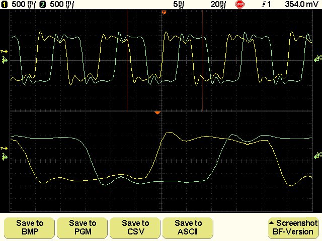
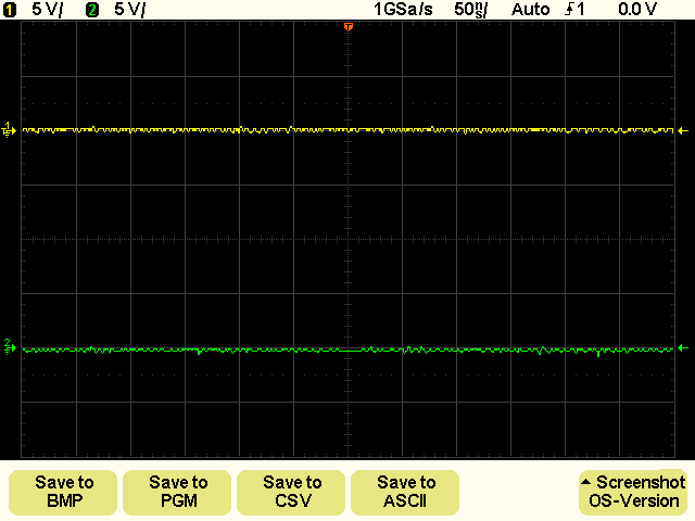
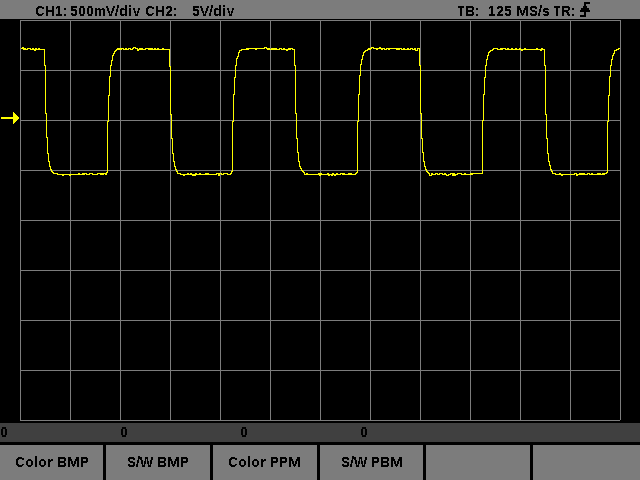
So, mit den richtigen Einstellungen (im Hardware-Menü usw.) machen
die Widerstände wirklich kaum eien Unterschied. Immer noch: gelb
mit 22 Ohm, grün mit 0 Ohm. Die Phasenverschiebung halt, sonst
fällt mir nichts auf.

Ich werde mal mit 100 MHz und mehr testen, aber habe ich bisher
einen rel. starken Frequenzgang. Mal weiter probieren.

Gruß, Guido
Moritz Z. schrieb :
> Grüße aus dem sonnigen Stuttgart,
>
> Moritz
>
> PS: Danke Michael das du mich Motiviert hast den Vorgang mit dem Updater
> abzubrechen!
> *edit:*
> PPS: Michael hat sich sogar die Mühe gemacht mir eine lange Email mit
> der genauen Vorgehensweise und möglichen Fehlern zu schreiben. Ich bin
> sprachlos! Tolles Forum!

...ja ja, so ein 'bißchen'  kann ich was!

Sag' mal Guido, wie kommt das bei dir mit den Rauschlosen Signalen
zustande??? Die Linien sind ja wie gemalt!!!

Hallo Rolf,

> Conrad* hat doppelseitig klebende Thermofolie.

Gib doch mal bitte die Art-Nummer, beim Conrad ist das immer so eine
Aktion, bis man da was findet, wäre nett, danke!
Den Conrad in FFM hatte ich mal zwecks der Folie nachgefragt: "hammer
net" war die Antwort...toll

Gruß Michael
Michael D. schrieb:
> Moritz Z. schrieb :
>> Grüße aus dem sonnigen Stuttgart,
>>
>> [Rauschen, etc]

Zum Rauschen würde es m.E. Sinn machen, folgende Meßreihen zu machen:

5-1V, Bandbreitenbegrenzt
50-10mV, nicht Bandbreitenbegrenzt

jeweils auf den gleichen Kanal, mit und ohne Widerstände, ohne
erneute Kalibrierung und ohne äußeres Signal, jeweils 1GSa/s.

Von diesen Messungen zieht mensch sich jeweils 2048 Werte aus
der Mitte und lässt sich die Standard-Abweichung geben.
Dies ist dann ein Maß für das (analoge) Rauschen.

Dazu dann noch die jeweilige Aussteuerung bei einem
Spannungsunterschied von: 30V (5V/DIV), 12V (2V/DIV), 6V (1V/DIV)
(oder halt 10V, 5V mit Ref-Quelle) - hieraus lässt sich das
Quantisierungsrauschen bestimmen.

Wg. des Frequenzganges könnte mensch sich auch mal die Oberwellen (3.
und 5.) eines entsprechenden Rechtecksignals ansehen. Leider ist mein FG
nicht kalibriert, so, dass ich nur die relativen Werte angeben könnte
(wenn ich die Widerstände drin habe) - davon abgesehen ist die
Auswertung auch etwas Arbeit.
>
>> Conrad* hat doppelseitig klebende Thermofolie.
>
> Gib doch mal bitte die Art-Nummer, beim Conrad ist das immer so eine
> Aktion, bis man da was findet, wäre nett, danke!
> Den Conrad in FFM hatte ich mal zwecks der Folie nachgefragt: "hammer
> net" war die Antwort...toll

Stichwort ist:

WÄRMELEIT-KLEBEFOLIE

darauf bekomme ich drei Treffer, von denen zwei interessant sind:

181132 - 62
181133 - 62

die, die ich mir damals besorgt habe, ist nicht dabei - vielleicht
finde ich noch die Bestell-Nummer.
>
> Gruß Michael

Grüße,

    rowue
Das Gefrickel mit den Faktoren erweist sich als etwas zäh. Es dauert
wohl noch etwas bis ich da was anbieten kann.


@Rolf

Danke für den Tip, ich werde da mal recherchieren.


Hayo
Moritz Z. schrieb:

> Wie es geklappt hat?
> Also:
> 1. Baudrate im Gerätemanager auf 115200 setzen
> 2. Adapter ohne Kabel anschließen
> 3. Die linken zwei Softbuttons gleichzeitig drücken, gedrückt halten,
> dann den Flash- oder Ramloader starten und sofort beide Tasten
> loslassen.

Kleiner Nachtrag zu den beiden linken Softbuttons:

- wenn Du erst den Linken drückst und hältst, dann den Rechten kurz
drückst und wieder losläßt bist Du im GERMS-Monitor über den sich die
Firmware laden läßt.

- wenn Du erst den Rechten der beiden drückst und hältst und dann den
Linken kurz drückst, macht das Gerät einen Reset.


> Nochmal Danke für alles!
>
> Grüße aus dem sonnigen Stuttgart,
>
> Moritz
>
> PS: Danke Michael das du mich Motiviert hast den Vorgang mit dem Updater
> abzubrechen!
> *edit:*
> PPS: Michael hat sich sogar die Mühe gemacht mir eine lange Email mit
> der genauen Vorgehensweise und möglichen Fehlern zu schreiben. Ich bin
> sprachlos! Tolles Forum!

Ja wir sind alle mal mit sehr wenig Detailwissen gestartet und waren
froh über jeden der uns weitergeholfen hat.

Hayo
Hayo W. schrieb:
> Das Gefrickel mit den Faktoren erweist sich als etwas zäh. Es dauert
> wohl noch etwas bis ich da was anbieten kann.
>
>
> @Rolf
>
> Danke für den Tip, ich werde da mal recherchieren.

Wenn Du in HH mal an dem Laden in Wandsbek/Dulsberg vorbeikommst,
da hatten die in der "Moder-Ecke" (wenn Du reinkommst rechts
hinten) 'ne Folie als Aktionsangebot, die 'nen Tick besser war.

>
>
>
> Hayo

Beste Grüße,

       rowue
So die Faktoren hab ich, aber ich komme erst morgen dazu ein Paket zu
schnüren.

Hayo
First thank all You very much for the hard work done!
Thanks to You I have a new functioning DSO, so many thanks!
I have a W2022A with a 1.4 original firmware by Welec.
Despite it is rated for 200MHz bandwidth I was not able to overcome
60MHz and the oscilloscope is pretty useless even at much lower
frequencies...
...with the original Welec's firmware is a disaster, DSO is very
limited!:-(
Ok, I paid it little money, I would say still too much for what it
provides.
But now thank to the firmware 1.2.BF.1.0 all my problems are gone!:-)))
Now I can reach 170MHz without problems, I could not test it well
because my RF generator stops at 170MHz.
So I tested it up to 170MHz sine wave and no problem, everything works
fantastically, I compared the results with a 150MHz analog oscilloscope
Hameg model 1500-2.
Unfortunately I do not have a 50ohm termination so my measurements were
performed with non-adapted line and then with reflections, but the
1500-2 Hameg showed the same things of Welec W2022A.
The only thing which I find is the mismatch between channel 1 and
channel 2, ie with the same signal applied to channel 1 and channel 2
waveforms are out of phase and phase depend by frequency.
I see discussions about this also here in the forum.
However I see in the UTILITY menu items CH1 DELAY and CH2 DELAY, so I
fix the problem.:-)
I saw other interesting things that were not there before, so I'm a
little confused about their use and I'd like to know where to find
information about them.
I've already written about the CH1 DELAY and CH2 DELAY functions and how
I used them.
Really I must use them so?
Why is the range from 0 to 16nS?
Still in the UTILITY menu in the HARDWARE tab there are items ADC SETUP
and PRE GAIN.
What about ADC SETUP?
And wath about PRE GAIN?
Inside ADC SETUP I see entries FACTORY, HIGH FREQ, TEST1, TEST2, TEST3
and TEST4, what are they mean?
How to use them?
My DSO has the original unmodified hardware so I chose FACTORY, but I
also tried HIGH FREQ and seems to work while TEST1, TEST2, TEST3 and
TEST4 provide different results.
How do I choose?
What I use?
Another thing about PRE GAIN.
There are entries FACTORY, GAIN 1.25, 24ohm, 33ohm, ADDON, what is they
mean?
How to use them?
My DSO has the original unmodified hardware, resistances were not
changed so I chose FACTORY, but other choices do not seem to make
difference.
How do I choose?
What I use?
And last for now, with AUTO SCALE function i see the SLOW TB entry, I
think it means SLOW TimeBase, is it correct?
How I must use it?
Inside 1.2.BF.1.0 firmware there are manuals, would be nice if there was
a list with a description of all functions and their use.
Perhaps already exists somewhere, but I can not find it.
This information would be useful because not all are engineers like You
then learn how to adjust certain things would be nice.
Again, perhaps this list already exists, perhaps it is right here in the
forum, unfortunately I do not understand very good German, I'm sorry.:-(
Vielen Dank!:-)

Luc
Hello Luc,

thanks for your post, Hayo will like it I guess.

Most of the functions you mentioned still are experimental, just
implemented to overcome users's problems. Some of us are doing
tests with modified hardware and Hayo tries to support this.

ADC-Setup: I tried today with this one. For low frequencies the
factory-setting should be best, but the menu seems to be not
correct. High-Freq seems to be the normal operation, for higher
frequencies test3 or test4 seems to be best.

Pre-Gain: I don't see any difference to.

I seldom use Auto-Scale, Slow-TB surely is Timebase, might be
left from the original firmware.

So long, Guido
@Luc

I'm sorry! As Guido found out the entries for Factory and high frequency
settings in the ADC-Setup menu are exchanged. It is fixed in the next
version which is available here today.

So let me explain the function. The factory setting results, as You can
see, in a resonance problem at higher frequencies. The HF-setting
deactivates some filters in the readout logic of the FPGA.

I always use the HF-Setting because it has the best results on my two
DSOs.

A few Users had some problems with spikes, so there are some other test
settings to find out which one matches to Your device.

The Pre Gain menu allows you to override the Factory setting of gain 1
at the 1er and 2er Ranges with the gain 1.25 - this may have a positive
effect to the noise level.

The other settings are for hardware modifications in the preamp stage on
the mainbord. Some users exchanged the line resistors (0 Ohm) at the
preamp input against 33 Ohm. Due to that You can choose other scaling
factors in this menu which fit to those modifications.


Hayo
Angehängte Dateien:
-

5V_0_Ohm.jpg
33 KB -

2V_0_Ohm.jpg
32 KB -

1V_0_Ohm.jpg
33 KB
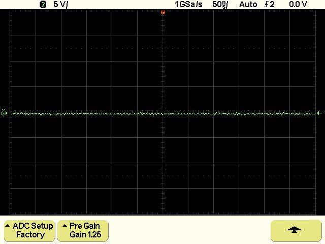
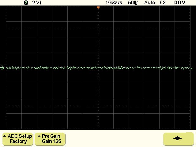
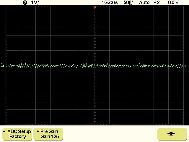
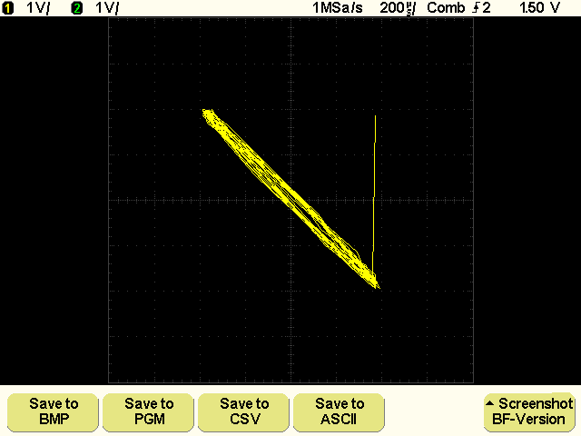
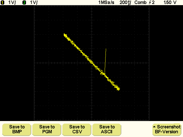
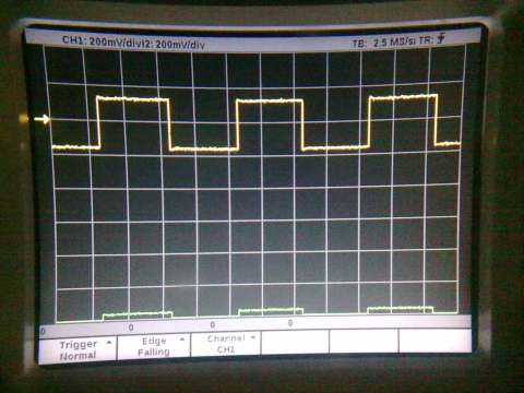
So Leute,

bevor ich die aktuelle BF.1.1 raushaue hier vorab einige Erkenntnisse zu
den so heiß umstrittenen Widerständen.

Als Referenz hier erstmal die drei Meßbereiche mit Gain 1.25 und Null
Ohm...
Angehängte Dateien:
-

5V_33_Ohm.jpg
31 KB -

5V_33_Ohm_2.jpg
30 KB

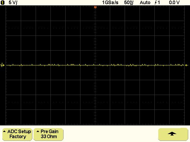
...dann der 5 V Bereich mit 33 Ohm und 150 Ohm statt 150 KOhm.

besonders auffällig ist die abhängigkeit von der vertikalen Position.
Wenn man mit dem Drehknopf etwas hin und her dreht wird es mal mehr und
mal weniger. Daher hier mal die beiden Extreme...
Angehängte Dateien:
-

2V_33_Ohm.jpg
34 KB -

1V_33_Ohm.jpg
34 KB

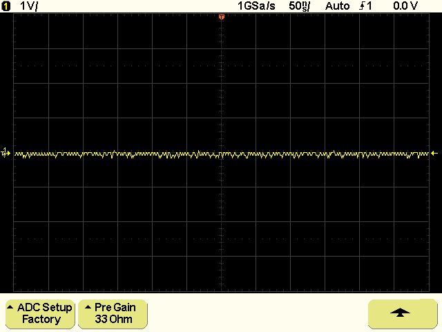
...zuletzt die 2er und 1er Bereiche. Hier het es sich meiner Meinung
nach deutlich verbessert.

Hayo
Interessant wäre jetzt noch das Frequenzverhalten. Ich werden das mal in
der nächsten Zeit prüfen.

Hayo
So, damit Ihr auch selbst ausprobieren könnt hier die BF.1.1

Ich habe bei der Gelegenheit alle!!! Skalierungsfaktoren neu berechnet
und feinjustiert.


Bitte beim 22 Ohm Bereich beachten dass ich hier nur Schätzwerte nehmen
konnte. Der 33 Ohm Bereich ist auf 33 Ohm mit zusätzlichem 150 Ohm
Widerstand statt des 150 KOhm Widerstandes ausgelegt evtl. passen die
Skalierungen nicht zum 150 K Widerstand! -> müßt Ihr testen


Gruß Hayo
Ach ja, noch einer!

Wenn Ihr zwischen den Gain-Bereichen wechselt solltet Ihr danach eine
DAC-Kalibrierung vornehmen, da sich der DAC-Korrrekturoffset evtl. auch
verändert.

Hayo
Angehängte Dateien:
-

Orig_0_ohm-5Volt_01.png
3,8 KB -

Orig_0_ohm-2Volt_02.png
4,2 KB -

Orig_0_ohm-1Volt_03.png
4,5 KB
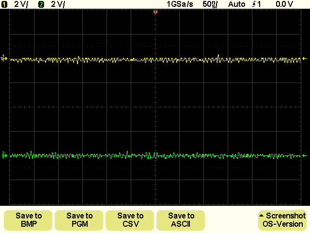
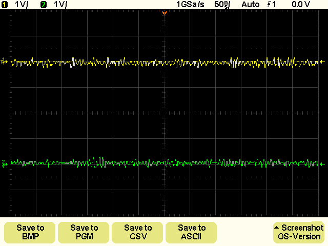
Hallo Hayo,

Dein Fleiß ist mal wieder beachtlich, wie du da reinhaust, wenn das so
weiter geht, werden die Dinger bald nicht mehr bezahlbar sein...

Wie hast du denn die Menuefuhrung auf den Screenshot gebracht?

Zum Vergleich mal dieselben Einstellungen, nur ohne Modifizierung!
Mich würde mal interessieren, ob das bei jedem gleich aussieht.

Ich warte jetzt noch das Frequenzverhalten ab, bevor ich was unternehme.

Noch was,
Einige hatten mit dem 2.Kanal Probleme mit der Null-Kalibrierung, bei
Signalmessungen ist da ein ordentlicher Versatz zu beobachten!
Nach einiger Zeit habe ich heraus gefunden, wie man beide Kanäle exakt
auf die Nullinie bekommt.
In diesem Fall war Combitrigger 1GSA/s 500µS und beide Kanäle mit dem
Pfeil übereinander, also PFEIL, nicht die Linie selbst!
Beide Pfeile genau in der Mitte vom Grid, dann eine Dac-Kalibrierung und
alles ist hübsch!
Bei Signalmessungen die übereinander liegen, sieht man kaum noch die
verschiedenen Kanalfarben, das hat mir gefallen!
Von der Grundstellung aus ging das bei mir nicht, hoffe der Tip war
nützlich.

Gruß Michael
Michael D. schrieb:
> Hallo Hayo,
>
> Dein Fleiß ist mal wieder beachtlich, wie du da reinhaust, wenn das so
> weiter geht, werden die Dinger bald nicht mehr bezahlbar sein...

Werden die eigentlich noch angeboten? Oder sind die jetzt nur noch
gebraucht zu kriegen?

> Wie hast du denn die Menuefuhrung auf den Screenshot gebracht?

Den Quick Print Button zweimal kurz hintereinander drücken, dann macht
er einen Screenshot ohne das Menü zu wechseln.

Die Screenshots entsprechen meinen ersten drei ganz oben, die sind auch
ohne Modifizierung bei Gain 1.25 geschossen. Bei Factory Setting ist das
Rauschen bei mir in den 1er und 2er Bereichen etwas höher.

Hayo
Hayo W. schrieb:
> Michael D. schrieb :
>> Hallo Hayo,
>>
> Werden die eigentlich noch angeboten? Oder sind die jetzt nur noch
> gebraucht zu kriegen?

habe gerade mal nach gesehen, da ich ja so'n 'Mikro' haben will, wurde
schon einmal überboten, ärgern...
es sind keine mehr zu sehen ausser OWON und ein TEK mit 500MHz für
kleines Geld...ähem 1999,- öcken
>
>> Wie hast du denn die Menuefuhrung auf den Screenshot gebracht?
>
> Den Quick Print Button zweimal kurz hintereinander drücken, dann macht
> er einen Screenshot ohne das Menü zu wechseln.

...klasse, wieso weiß ich das nicht? Muß jedes mal mit der Kamera und
Lupe rum rennen, wenn der kompl. Bildschirm drauf soll!
>
> Die Screenshots entsprechen meinen ersten drei ganz oben, die sind auch
> ohne Modifizierung bei Gain 1.25 geschossen. Bei Factory Setting ist das
> Rauschen bei mir in den 1er und 2er Bereichen etwas höher.

ach, diese Einstellung ist dann zu empfehlen?
>
> Hayo
Was macht denn so deine Frequenzmessung, schon was konkretes heraus
gekommen?
Weil mit dem Beitrag vom branadic der Wind aus den Segeln genommen wird,
siehe hier:
Beitrag "Re: Wittig(welec) DSO W20xxA Hardware"

Gruß Michael
Michael D. schrieb:

>>> Wie hast du denn die Menuefuhrung auf den Screenshot gebracht?
>>
>> Den Quick Print Button zweimal kurz hintereinander drücken, dann macht
>> er einen Screenshot ohne das Menü zu wechseln.
>
> ...klasse, wieso weiß ich das nicht? Muß jedes mal mit der Kamera und
> Lupe rum rennen, wenn der kompl. Bildschirm drauf soll!

Hatte ich schon seit der 0.92 drin glaube ich, müßte ich mal als readme
beifügen...


>> Die Screenshots entsprechen meinen ersten drei ganz oben, die sind auch
>> ohne Modifizierung bei Gain 1.25 geschossen. Bei Factory Setting ist das
>> Rauschen bei mir in den 1er und 2er Bereichen etwas höher.
>
> ach, diese Einstellung ist dann zu empfehlen?

würde sagen ja

>> Hayo
> Was macht denn so deine Frequenzmessung, schon was konkretes heraus
> gekommen?

Komme erst übermorgen dazu, da ich morgen den ganzen Tag aushäusig bin.

> Weil mit dem Beitrag vom branadic der Wind aus den Segeln genommen wird,
> siehe hier:
> Beitrag "Re: Wittig(welec) DSO W20xxA Hardware"

mal schaun

Hayo
@Guido and @Hayo

Hi guys, Guido, Hayo and all.
Thank You very much for answers and useful information.
OK I understand these are experimental features, however I see that they
work well.
I have not yet tried the 1.2.BF.1.1 release but I will do soon.
About ADC SETUP I set it as a FACTORY with my W2022A and I have not
encountered problems with both low and high frequency.
I must clarify that I tested from 1.7MHz to 170MHz, I have not tried
with low frequency, not even with the internal 1KHz calibrator, but now
that I know it I will do it certainly!
However it is true, You are right, with some oscilloscopes there are
problems with spikes.
Today a my friend lent me his W2012A for tests.
First I tried it with a 1.4 original firmware by Welec and despite it is
rated for 100MHz bandwidth I was not able to overcome 60MHz and the
oscilloscope is pretty useless even at much lower frequencies just like
my W2022A (I performed the same tests from 1,7MHz to 170MHz sine wave).
Then I upgraded it to 1.2.BF.1.0 firmware release and so I had some
surprises.
At the beginning I saw the spikes on track channel's 2.
These spikes were sporadic and the track channel's 1 was totally free of
spikes.
After a while the spikes disappeared, I thought it was a temperature
problem i.e. the oscilloscope was switched on recently and had not yet
reached its steady heat.
Perhaps the spikes disappeared after I set FACTORY's parameters in ADC
SETUP, I do not know, I have not done carefully.
However the spikes are gone!
Everything worked well like with my W2022A and surprise the W2012A
easily reach 170MHz just like my W2022A!, I have not noticed significant
differences.:-)
Now that you have told me as it works, I'll try other settings to see if
it  further improves: THANKS!:-)))
OK for PRE GAIN's settings.
Yes, perhaps SLOW TB comes from the 1.4 original firmware by Welec, I'll
try to check in the manual to understand how to use the SLOW TB
function.
Just one last thing about the CH1 DELAY and CH2 DELAY.
I have already written as I used these function and why but I did not
understand if I did it correctly.
With the same signal applied to channel 1 and channel 2 waveforms are
out of phase and I fix the problem with CH1 DELAY and CH2 DELAY
functions.
I did it correctly?
About modified hardware it is interesting.
I would not have problems to make resistance's change as You suggest and
certainly I will do it in the future.
But for my purposes with your new firmware the DSO works very well so I
wait until the warranty expires before putting my hands, although I
honestly do not know whether or not trust of the manufacturer for
assistance.
We'll see.
For now, thanks to all!
Vielen Dank!:-)

Luc
Michael D. schrieb:
> Hayo W. schrieb:
>> Michael D. schrieb :
>>> [...]
>
> ...klasse, wieso weiß ich das nicht? Muß jedes mal mit der Kamera und
> Lupe rum rennen, wenn der kompl. Bildschirm drauf soll!

Ganz fiese Frage - hast Du mal in den ersten Teil des Threads
geschaut? - Da wurde das bei der Einführung angesprochen ;)
>>
>> [...]
>
> Gruß Michael

Grüße,

   rowue
Rolf W. schrieb:
> Michael D. schrieb:
>> Hayo W. schrieb:
>>> Michael D. schrieb :
>>>> [...]
>>
>> ...klasse, wieso weiß ich das nicht? Muß jedes mal mit der Kamera und
>> Lupe rum rennen, wenn der kompl. Bildschirm drauf soll!
>
> Ganz fiese Frage - hast Du mal in den ersten Teil des Threads
> geschaut? - Da wurde das bei der Einführung angesprochen ;)
>>>
boahh, ganz fiese Antwort - hast du mal die Länge des 1.Threads geprüft?
Ich habe bestimmt 7/8tel 'grins' davon gelesen und Einiges ist hängen
geblieben, denke ich!
Hier gibt's Leute, die haben die letzten 3 Beiträge nicht gelesen und
fragen trotzdem... dann schickt man halt einen Link und gut is'!
...ich mag dich trotzdem 'lächel' nicht falsch verstehen, bin absolut
hetero.....

>>> [...]
>>
>> Gruß Michael
>
> Grüße,
>
>    rowue

auch Gruß Michael

...und wieder kein Mikro ersteigert, heut' ist der Wurm drin.
Hi Luc,

at the moment I don't suggest any harware modifications. We are testing
about that but the results seem to be only minor advantages. The most
important change was the firmware-hack unenabling some sort of
FIR-filter
in the FPGA-design. This was done before the 1.0 firmware.

I am aware of the spikes during warmup too, after 2 minutes or so the
spikes vanish.

I own a W2012A andt there seems to be no difference to the W2022A,
maybe Welec did some hardware-selections? I can't imagine.

See you, Guido
Luc schrieb:
> @Guido and @Hayo
> I have not yet tried the 1.2.BF.1.1 release but I will do soon.
> About ADC SETUP I set it as a FACTORY with my W2022A and I have not
> encountered problems with both low and high frequency.

In the BF.1.1 I exchanged the values of the menu-entries for factory
setting and high frequencies - in the BF.1.0 it is the wrong order!


> First I tried it with a 1.4 original firmware by Welec and despite it is
> rated for 100MHz bandwidth I was not able to overcome 60MHz and the
> oscilloscope is pretty useless even at much lower frequencies

In the original Firmwares all the lower timebases are set to the same
settings as the 50ns Timebase - and therefore are extremely useless!!!


> Everything worked well like with my W2022A and surprise the W2012A
> easily reach 170MHz just like my W2022A!, I have not noticed significant
> differences.:-)

Until now we didn't find any differences in the Hardware between the 100
MHz and the 200 MHz Version. I myself got a W2022A and a W2014A. My
HF-Tests revealed no great Differences between the two DSOs.


> Yes, perhaps SLOW TB comes from the 1.4 original firmware by Welec, I'll
> try to check in the manual to understand how to use the SLOW TB
> function.

Hmm, I didn't use this until now. I will check it.

> Just one last thing about the CH1 DELAY and CH2 DELAY.
> I have already written as I used these function and why but I did not
> understand if I did it correctly.

Yes, You did. We (the guys here in the forum) checked the channel
phaseshift of our DSOs and found out that they differ about 2ns and 8ns
between the channels. So I think the maximum of 16 ns for each channel I
provided in the delay menu are more than enough to bring all channels in
phase.

Please notice, that the BF.1.0 has a little bug in the DAC-Calibration
function which only appears at some channel delays (I tried 7ns).
It is fixed in the BF.1.1.

I think I should write a little manual for the new functions...

For example the the Quick Print function. Pushing it two times initiates
the screenshot function without changing the menu - did You know that?


Hayo
Hayo W. schrieb:
> I think I should write a little manual for the new functions...
>
...fine!
>
>
> For example the the Quick Print function. Pushing it two times initiates
>
> the screenshot function without changing the menu - did You know that?
>
>
no, I didn't and I bet that someone else didn't know that ether ;)
...but now I, we do! :)
>
>
>
> Hayo

Greetings Michael
Hallo,

mit der 1.1 habe ich jetzt große Unterschiede zwischen den beiden
Kanälen. Werden die jetzt unterschiedlich behandelt? Würde ja
Sinn machen.

Ich probiere im Moment mit Pre-Gain = 1,25, da sollten doch beide
Kanäle gleich behandelt werden.

Gruß, Guido
Guido schrieb:
> Hallo,
>
> mit der 1.1 habe ich jetzt große Unterschiede zwischen den beiden
> Kanälen. Werden die jetzt unterschiedlich behandelt? Würde ja
> Sinn machen.

Eigentlich nicht...

> Ich probiere im Moment mit Pre-Gain = 1,25, da sollten doch beide
> Kanäle gleich behandelt werden.

vielleicht hab ich da noch nen Zinken drin. Beschreibe doch mal was da
unterschiedlich ist bzw. poste es als screenshot.

Hayo
Hallo Hayo,

es sind einfach die Amplituden der beiden Kanäle stark verschieden und
das Ganze frequenzabhängig. Aus der Erinnerung:

bei 1 kHz zeigt Kanal 2 (0 Ohm) ca. eine um 30 % höhere Amplitude an,
bei 30 MHz dann Kanal 1 (22 Ohm) etwa die doppelte Amplitude gegenüber
Kanal 2.

Ich werde das später noch mal genauer untersuchen, aber der Aufbau
steht eigentlich noch von meiner Frequenzgangmessung.

Gruß, Guido
Verstehe ich das richtig, dass Deine Kanäle unterschiedlich bestückt
sind?

Hayo
Ja, ist doch schon länger so. Hast du alle Kanäle geändert?

Wenn es an der 1.1 läge, müsste das doch auch jemand anders
aufgefallen sein?
Dann ist es aber doch klar, dass die Kanäle unterschiedlich aussehen. Da
versteh ich das Problem nicht so richtig. Bei meinem W2022A hab ich auch
einen Kanal original und einen mit 33 Ohm bestückt. Da gibt es natürlich
auch Unterschiede in der Amplitude - Frequenzabhängigkeiten hab ich
allerdings noch nicht getestet.

Gruß Hayo
Schon aber der Unterschied war sehr gering (1/4 Div oder so).
Den Frequenzgang habe ich ja vorgestern verglichen (s.
Hardwarethread). Jetzt dagegen die großen Unterschiede?
Oops, peinlich. Ich habe das Problem gelöst:

Wenn man einen SA als Abschlusswiderstand nimmt, solte dieser
auch eingeschaltet sein. Etwas verblüffend, dass sich das auch
bei sehr niedrigen Frequenzen (1 kHz) bemerkbar macht.

Gruß, Guido
...na dann ist ja alles gut (schwitz...)

Hayo
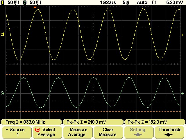
So, neue (alte) Erkenntnisse zum Frequenzverhalten. Da ich zu faul bin
meine Messreihen in Exel zu tippen, hier eine grobe Zusammenfassung.

Zum Messaufbau:

Meine Möglichkeiten zum HF-Messen sind leider sehr begrenzt. Bis 60 MHz
Grundfrequenzreicht mein Generator. Trotzdem sind die Resultate sehr
interessant und bestätigen die Messungen die im Hardwarethread gepostet
wurden.

Generator: HP3325A  20MHz mit Amplituden bis 40V, 60 MHz mit 0dB
Referenz Oszi: Tek 2465A (350 - 400 MHz Bandbreite)

Bei Frequenzen bis 20 MHz gibt es zwischen der 0 Ohm Variante und der 33
Ohm Variante keine nennenswerten Unterschiede. Mit steigender Frequenz
steigt die Amplitude bei der Originalbestückung deutlich an während die
33 Ohm Variante da eheblich genauer ist.

Das Signal bei 60 Mhz hat Überschwinger mit Frequenzanteilen die
deutlich höher sind als die Grundfrequenz.

Die gemessenen Amplituden incl. Überschwinger:

Referenz Tek:     464 mV
Welec mit 0 Ohm:  744 mV
Welec mit 33 Ohm: 528 mV

Das sind 280 mV zuviel bei 0 Ohm und nur 64 mV bei 33 Ohm.

Der Amplitudengang verläuft also mit den 33 Ohm Widerständen deutlich
linearer als mit den 0 Ohm Widerständen.

Zusammen mit der Tatsache das auch das Rauschen in den 1er und 2er
Bereichen etwas abnimmt ist das für mich Grund genug auch den Rest mit
33 Ohm zu bestücken.

Hayo
Noch ein kleiner Nach(t)gedanke:

es kann natürlich sein, dass der ausgetauschte 150 KOhm Widerstand
(gegen 150 Ohm) maßgeblich am Fequenzgang beteiligt ist und nur die
Kombination aus beidem diesen positiven Effekt hat.

Hayo
Jo, den Nachtrag halte ich auch für relevant. Ich werde später
auch nochmal nachmessen, ich fürchte mein letzter Frequenzgang
war durch den SA verzerrt. Dann haben wir den vergleich mit
150 kOhm.

Gruß, Guido
@Guido and @Hayo

Hi Guido, Hayo and all guys.
Thank You very much for for the useful details!
OK, for changes in the hardware I think like You Guido.
In fact, to be honest watching the screenshots I think the improvements
are marginals, but I could be wrong because I do not understand very
well the German language.
I believe that the new firmware make the difference, the hardware is
what it is and it can be left as it is.
However we will see.
For spikes problem which I wrote and Guido confirm, I think it's a warm
up problem, once thermally stabilized the DSO works without problems.:-)
However, the W2022A does not have that problem, at least what I have so
the hardware-selections hypothesis could be right.
About the wrong  values of the menu-entries of BF.1.0 firmware mentioned
by Hayo, with my W2022A I have not had problems with both FACTORY that
HIGH FREQ, as I have already had occasion to write.
Very good for the BF.1.1 firmware version that was promptly corrected by
Hayo, good as usual, thanks!:-)
Unfortunately I'm still doing tests with the BF.1.0 version but I will
the upgrade soon.

Hayo W. schrieb:
>
>> First I tried it with a 1.4 original firmware by Welec and despite it is
>> rated for 100MHz bandwidth I was not able to overcome 60MHz and the
>> oscilloscope is pretty useless even at much lower frequencies
>
>In the original Firmwares all the lower timebases are set to the same
>settings as the 50ns Timebase - and therefore are extremely useless!!!
OK, thanks for the information Hayo!:-)
Still using the BF.1.0 firmware, today I did further testing with my
friend's W2012A.
Using a very crude free oscillator I reached about 250MHz with the
W2012A.
250MHz is the limit of the frequency meter of my Hameg 1500-2.
Free oscillator signal was not very stable and clean but the W2012A
showed about the same things of the Hameg 1500-2!:-)
At 200MHz things were better so roughly the W2012A can be considered a
200MHz, however my tests are not rigorous: I consider the displayed
waveform rather than their levels.

Hayo W. schrieb:
>> Everything worked well like with my W2022A and surprise the W2012A
>> easily reach 170MHz just like my W2022A!, I have not noticed significant
>> differences.:-)
>
>Until now we didn't find any differences in the Hardware between the 100
>MHz and the 200 MHz Version. I myself got a W2022A and a W2014A. My
>HF-Tests revealed no great Differences between the two DSOs.
I agree.

For the SLOW TB function I must investigate, in case I try with Welec,
I'll see what they respond to me.
OK Hayo for your answer to my question about CH1 DELAY and CH2 DELAY and
OK for its bugfix in the BF.1.1 firmware!
Now I understand!:-)

Hayo W. schrieb:
>I think I should write a little manual for the new functions...
>
>For example the the Quick Print function. Pushing it two times initiates
>the screenshot function without changing the menu - did You know that?
I'm Sorry, I did not know this, however I do not often use that function
but I will do soon.
What can I say?
Very well guys, thanks very much!:-)
Vielen Dank!:-)

Luc
Hayo W. schrieb:
> Noch ein kleiner Nach(t)gedanke:
>
> es kann natürlich sein, dass der ausgetauschte 150 KOhm Widerstand
> (gegen 150 Ohm) maßgeblich am Fequenzgang beteiligt ist und nur die
> Kombination aus beidem diesen positiven Effekt hat.
>
> Hayo

Ich gebe mal meinen Senf dazu, weil ich ein wenig aufgepasst habe:

Hier waren ja die Berechnungen (laut Andre?) damit der Abschluss 1100
Ohm beträgt...
Beitrag "Re: Wittig(welec) DSO W20xxA Open Source Firmware (Teil2)"

dann wäre Hayo's Konstellation mit den 2 x 33 Ohm und dem 150 Ohm,
der Abschlusswiderstand über 1100 Ohm!
Würde die Amnplitude mit 100 Ohm (statt 150 Ohm) noch weiter sinken, was
ja eigentlich logisch wäre, da der Abschlusswiderstand ja niedriger
wäre,
oder wie verhält sich das?

Gruß Michael
Hi Luc,
a comnent to Your high frequency test. We fomd out that the amplitude
increases at frequencies between 50 ~ and 200 Mhz. So the amplitude
response
is not linear, but has a maximm aromd 150 Mhz.

http://sourceforge.net/apps/trac/welecw2000a/wiki/HardwareImprovement

I made some tests with my modified hardware ( I changed the input
resistances of 0 0hm against 33 0hm and the 150 KOhm parallel resistmce
against 150 Ohm) and fomd out that the amplitude response is much more
linear now.

Beitrag "Wittig(welec) DSO W20xxA Open Source Firmware (Teil2)"

So I think I will change all other resistances too. But in the normal
case
of measuring at 20 or 30 mz You are right, it is not so importmt as the
firmware with all its functions.

Hayo
Angehängte Dateien:
-

qm.jpg
68 KB
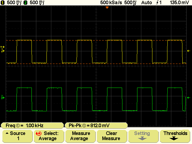
Ohoh Hayo,

ich habe meine Messungen gerade abgebrochen, Die Quick.Measure-Funktion
scheint unter die Räder gekommen zu sein. Gast du Kästchen gezählt?

ADC war beim Bild auf Factory gestellt.

Gruß, Guido
O.k. I'll try this one in english.

If Hayos's results are confirmed and we start changing the resistors,
we should do that according to the datasheet's hints. I'll have a
lokk tomorrow. Doing that we should change the OPA's feedback resistor
as well, to increase the gain and use the ADC's full resolution.
There will be a decrease in bandwith along, but this might be
süperseeded by the increase in gain we jet have with higher
frequencies.

Regards, Guido
@Guido

Ich habe meine Messungen nicht mit Quick Measure gemacht, sondern mit
den manuellen Cursorn. Die Werte die ich da ermittelt habe sind schon
korrekt.

Hayo
Allerdings hast Du recht in Bezug auf die QM-Funktion, ich bin da
ebenfalls auf Verbesserungspotential gestoßen...


Hayo
@ Hayo: Ich habe gerade nachgeschaut, die Cursor-Werte stimmen nur
bei Pre-Gain = Factory. Gibt wohl noch ne Menge Arbeit.
Guido schrieb:
> @ Hayo: Ich habe gerade nachgeschaut, die Cursor-Werte stimmen nur
> bei Pre-Gain = Factory. Gibt wohl noch ne Menge Arbeit.

Wie ist das gemeint? Ich habe auch nachgeschaut und die Cursorwerte
stimmen für alle Bereiche - oder meintest Du QM-Cursorwerte?

Hayo
Nichtsdestotrotz hat mir die QM-Sache keine Ruhe gelassen. Es gibt daher
mal wieder eine neue Version...

What is new:

- Ticket #31 gefixt

http://sourceforge.net/apps/trac/welecw2000a/ticket/31

- QM support für USTB modus

- QM menü Einträge korrigiert (QM-Selection)

Viel Spass

Hayo
Ich habe es getan! Das USB-Mikro ist bestellt für 50 Ocken plus 5 Ocken
Versand.

Bin mal gespannt...

Hayo
Hallo Hayo,

eine Screenshot " 1.5 " ???

Die QM hatte nur Probleme ab 60MHz ?

Gruß Michael
Michael D. schrieb:
> Hallo Hayo,
>
> eine Screenshot " 1.5 " ???

ja ich hab die Farbpalette noch etwas geändert und dann die
Versionsnummer auf den aktuellen Stand gebracht. Ist aber völlig
losgelöst vom dem OS-Screenshot, der auch anders komprimiert.

> Die QM hatte nur Probleme ab 60MHz ?

Wie ist das gemeint?

Hayo
Angehängte Dateien:
-

QuickMeasure_RoteLinie.png
4,7 KB
Weil Guido's Quick-Measure unter die Räder gekommen sind? Ab wann oder
wo, tritt das ein?

Hast du was am Auto-Trigger gedreht? Der Zappelt ja garnicht mehr,
vielleicht hat mein Teil auch nur einen guten Tag!

Die 0,48er sowie die 1.5 Screensh. zickt bei mir rum, ist sehr langsam
und es tut sich manchmal nix...während die Os-Variante gleich anschlägt
und hat zackich' das Bild generiert. Die Port-Einstellungen sind alle
Dieselben. 115200 baut, Datenbits: 8, Parität: keine, Stoppbit: 1,
Flussst.: keine !
Baudrate, Handshake???

Noch was, beim Quick-Measure habe ich die roten Linien im Signal (oben
u. unten), das war vorher nur im Curser-Modus.

Gruß Michael

PS.: 2x Quickprint funktioniert prima, feine Sache...
Beim Quick-Print habe ich auch das Problem, dass ich erst den
Menüpunkt BF/OS aufrufen muss. Ohne dort etwas zu ändern klappt
es anschließend. Wird doch kein Initialisierungsproblem sein. :-))

@ Hayo: Für 55 Öcken kann man ja nicht viel falsch machen.
Andererseits ist eine Nahlinse für die Digicam auch nicht teurer.

Soll ich mal wieder einen Frequenzgang posten? Mal sehen, ob ich
das irgendwann mal fehlerfrei hinbekomme.

Grüße, Guido
Michael D. schrieb:
> Weil Guido's Quick-Measure unter die Räder gekommen sind? Ab wann oder
> wo, tritt das ein?

Keine Ahnung, hatte das Phänomen noch nie, bei mir läuft alles stabil.

> Hast du was am Auto-Trigger gedreht? Der Zappelt ja garnicht mehr,
> vielleicht hat mein Teil auch nur einen guten Tag!

Nix gemacht.

> Die 0,48er sowie die 1.5 Screensh. zickt bei mir rum, ist sehr langsam
> und es tut sich manchmal nix...während die Os-Variante gleich anschlägt
> und hat zackich' das Bild generiert.

Die OS-Version ist tatsächlich einfach schneller! Bei der BF-Version muß
man etwas länger warten, ich hatte es auch mal, das er das Bild erst
gespeichert hat nachdem ich am Oszi irgendeine Taste betätigt hatte.

Allerdings ist das bei mir schon länger nicht mehr aufgetreten.

> Noch was, beim Quick-Measure habe ich die roten Linien im Signal (oben
> u. unten), das war vorher nur im Curser-Modus.

Auf Deinem Screenshot oben liegt es daran, das die obere Kante des
Signals so glatt ist. Normalerweise wird die rote Linie von einzelnen
Minispikes nach oben gedrückt. Da hab ich aber nichts geändert, ist also
so wie vorher und auch in der OS-Version.

Hayo
Guido schrieb:
> Beim Quick-Print habe ich auch das Problem, dass ich erst den
> Menüpunkt BF/OS aufrufen muss. Ohne dort etwas zu ändern klappt
> es anschließend. Wird doch kein Initialisierungsproblem sein. :-))

Muß ich mal prüfen. Kann es sein, das das nur nach dem Flashen auftritt
und dann nicht mehr?


> Soll ich mal wieder einen Frequenzgang posten? Mal sehen, ob ich
> das irgendwann mal fehlerfrei hinbekomme.

Ja, aber dann mit kurzer Info über die Widerstandsbestückung der
Längswiderstände und des Parallelwiderstands.

Gruß Hayo
Ich glaube eigentlich nicht, dass es nur nach dem Flashen so ist,
kann das später aber noch probieren.

Zum Frequenzgang: Reihenwiderst. sind angegeben,
Abschlusswiderstand ist im Originalzustand. Die Kurve ist nicht sehr
genau aufgenommen (+-25 mV oder so), soll nur den Trend zeigen.

Gruß, Guido
Noch mal zum Verständnis: bis 100 MHz ist es im Originalzustand
definitiv besser - der Peak kommt halt später.

Bis jetzt bin ich von der Widerstandsmodifikation nicht überzeugt.

(Nicht das mich jemand falsch versteht - vielen Dank, das das jemand
ausprobiert und dabei seine Kiste aufs Spiel setzt!)

Bringt denn der geänderte Parallelwiderstand etwas?

(Ich habe leider in diesem Monsterthread etwas den Überblick verloren)

Viele Grüße,

egberto
hmm, bei 0 Ohm und Noise-Filter, geht das Sig. ganz schön in den Keller,
während bei der Bestückung sich das in Grenzen hält.
Wenn noch der Abschwiderstand getauscht wäre, würde mich mal
interssieren, wie's dann aussieht!


Gruß Michael
sorry, hab ich ich nicht verstanden - 0 Ohm denoise sieht für mich noch
am besten aus!? (Ziel ist doch eine waagerechte Gerade oder?)

Viele Grüße,

egberto
@Hayo

Hi Hayo and all guys.
Very good for the new BF.1.2, good as usual, thanks!:-)
Soon I will upgrade to the new release.;-)

Hayo W. schrieb:
>
>Hi Luc,
>a comnent to Your high frequency test. We fomd out that the amplitude
>increases at frequencies between 50 ~ and 200 Mhz. So the amplitude
>response is not linear, but has a maximm aromd 150 Mhz.
>
>http://sourceforge.net/apps/trac/welecw2000a/wiki/...
I already read it, anyway thanks for reminding me.

Hayo W. schrieb:
>
>I made some tests with my modified hardware ( I changed the input
>resistances of 0 0hm against 33 0hm and the 150 KOhm parallel resistmce
>against 150 Ohm) and fomd out that the amplitude response is much more
>linear now.
>
>Beitrag "Wittig(welec) DSO W20xxA Open Source Firmware (Teil2)"
>
>So I think I will change all other resistances too. But in the normal
>case of measuring at 20 or 30 mz You are right, it is not so importmt as
>the firmware with all its functions.
I know and I agree.
As I said my tests are not rigorous, I consider the displayed waveform
rather than their levels.
I often use old vacuum state tube oscilloscopes of the 50s of last
century and I do comparative rather than quantitative measures because
they are not "calibrated".
So I can do same with Welec, this is the meaning of what I wrote.
In this context for me is more important the fidelity of the track
rather than its actual values of amplitude.
Then it is obvious that if it is possible to make more linear the
amplitude response better is and I would be happier also.:-)
But I think already the software does a very good job without having to
alter the hardware.
I also think that change the hardware is not for everyone, I would not
have problems but I believe that not for all would be so easy.
The firmware update instead is accessible to all and at present I think
it bring many more benefits that the change of resistances, in the
future we will see.
Vielen Dank!:-)

Luc
Hallo,

jepp egberto, das siehst du richtig. es sollte eine Gerade über
200 mV sein und die ursprünglichen Widerstände kombiniert mit
Hayos Rauschfilter liefern das beste Ergebnis. Allerdings habe
ich bei dieser Messung ("wer misst misst Mist") schon so viele
Fehler begangen, dass es mich nicht wundern würde, wenn es morgen
wieder anders aussieht. Wäre daher schön, wenn das andere auch
nur teilweise nachmessen könnten.

@ Luc: We all are lacking optimal equipment. we just try to find
out the most reliable values for the resistors in the input-stage.
The overall response could then be linearized by software.
By the way: The user branadic is engineering a new input stage. We
are looking forward upon this.

Gruß, Guido
Ich bin ja doof, hatte da visuell etwas verwechselt...
Noch ein kurzes Zwischenergebnis.

Ich habe den Parallelwiderstand auf 100 Ohm gesetzt und nochmal gemessen
- keine Änderung (außer der Skalierung) im Amplitudengang gegenüber den
150 Ohm. D.h. ich werde auf 150 Ohm zurückrüsten, da hier die Skalierung
günstiger ist.

Grundsätzlich kann man aber schon sagen, dass die Umrüstung auf 33/150
Ohm
für HF-Messungen Sinn macht. Ansonsten (< 20 MHz) wirkt es sich nicht so
stark aus, insbesondere wenn man den Noisefilter benutzt.

Da ich ja zwei Geräte habe, werde ich das W2022A umrüsten und das W2014A
original lassen, dann hat man auch immer einen Vergleich.


Hayo
@Guido

Du solltest auf jeden Fall auch den Parallelwiderstand austauschen (150
Ohm bietet sich an), sonst macht das nur wenig Sinn.

Wenn Du bei 22 Ohm für die Serienwiderstände bleiben willst brauchst Du
geänderte Skalierungsfaktoren. Ich kann Dir anbieten das Coding zu
schicken incl. kurzer Anleitung was Du tun must.

Hayo
@ Hayo: Ich muss das erst mal durchrechnen. Wie schon geschrieben
möchte ich bei der Gelegenheit gleich die Verstärkung anheben, so
dass die ADCs bis auf +-127 ausgesteuert werden.

Ich baue später mal einen Frequenzvervielfacher (ICS502) auf,
damit ich das Welec mal mit Rechtecksignalen bis 100 MHz
traktieren kann.

Gruß, Guido
Sorry für Doppelpost.

@ Hayo: Mit den Widerständen musst du die Spannungen mit 1,44
multiplizieren, liege ich da richtig?
Guido schrieb:
> Sorry für Doppelpost.
>
> @ Hayo: Mit den Widerständen musst du die Spannungen mit 1,44
> multiplizieren, liege ich da richtig?

nicht ganz:

bei 33/150 Ohm sind es 1,51
bei 33/100 Ohm sind es 1,65

Hayo
Hello, could someone explain me how to hardware modify? I want to change
the resistance but can not find a schematic to identify those to be
replaced. And then use that value, 24 or 33ohm?
What benefits you have with this change? Higher linearity and lower
noise, right?

Thanks, Gyppe.
Hi Gyppe,

thats right. I will post a Photo in the Hardwarethread in a few minutes

Hayo
Guido schrieb:
> @ Hayo: Ich muss das erst mal durchrechnen. Wie schon geschrieben
> möchte ich bei der Gelegenheit gleich die Verstärkung anheben, so
> dass die ADCs bis auf +-127 ausgesteuert werden.
>
Hallo Guido,

...da bin ich mal gespannt!

> Ich baue später mal einen Frequenzvervielfacher (ICS502) auf,
> damit ich das Welec mal mit Rechtecksignalen bis 100 MHz
> traktieren kann.

Rechteck mit 100MHz? Wie sieht das dann noch aus???
>
> Gruß, Guido

Gruß Michael
So, ein Problem habe ich jetzt eingekreist:

Wenn beim Abschalten das Oszi im FFT-Modus war und ich diesen
nach dem nächsten Einschalten verlassen will, werden bei meinem
W2912A Kanal 3 und 4 aktiviert und lassen sich nicht mehr
ausschalten (hab ja keine Taster dafür). Dann hilft nur noch
Default-Setup, worauf dann aber auch die Kalibrierung der ADC
und der DAC zum Teufel ist.

Den umgekehrten Fall muss ich noch genauer untersuchen, da gibt
es aber auch Probleme.

Gruß, Guido
Wieso ist nach einem Default Setup die Kalibrierung zum Teufel???

Die sollte eigentlich nicht geändert werden.

Das Problem mit Kanal 3 + 4 werde ich mir mal ansehen.


Hayo

p.s. hast Du ein neues Modell W2912A? ;-)
> Wieso ist nach einem Default Setup die Kalibrierung zum Teufel???

Ja, das wundert mich auch. Ich erjenne es nur an den Störungen, die
nach neuer Kalibrierung wieder besser sind.

> p.s. hast Du ein neues Modell W2912A? ;-)

Naja, nach jedem Zerlegen die V-Nummer dort erhöht, wo es nicht so
stört (puuh, sollte doch die Brille aufsetzen).

Gruß, Guido
Hmm muß ich wohl mal checken, war mir noch nicht aufgefallen. Das soll
ja so nicht sein...

Hayo
Kann ich ebenfalls so bestätigen, nach dem einschalten ist die FFT
wieder da aber beim verlassen hab ich 2 kanäle mehr...
Mensch, seid doch froh, meldet sich das Oszi dann auch als W2024A ;-)

Ich werde da mal einen Fix in den nächsten Tagen rausbringen.

Hayo
Also zum Thema Default Setup:

Definitiv werden DAC-Offset und ADC-Offset nicht dadurch verstellt! Ich
habe mehrere Tests gemacht und es funktioniert wie es soll!!!


Folgende Situation habe ich bei mir aber öfters mal gehabt:

Nach einem Flashvorgang mit einer neuen Version hingen die Signale
völlig schief, danach ein Default Setup und alles ist wieder gut.
Allerdings waren da jedesmal die Kalibrierungen hinüber. Das liegt dann
aber nicht am Default Setup, sondern an der Startup-Routine, die nach
dem Laden einer neuen Firmware das Flash neu initialisiert, um bei
geänderter Flashkonfiguration die Werte neu zu belegen und das Gerät
nicht ins Nirwana zu schicken.

Hayo
Hmmh, ob ich den Junge zu grob anfasse? Ich habe vorhin wieder
das ganze Programm durchgezogen. Auch unter Utility->more->Hardware
hatte er alles vergessen.

Wir werden es rausfinden!

Gruß, Guido
Hallo, einen schönen 1. Mai wünsche ich,

ich überarbeite gerade die Initialisierungsroutine um das mal entgültig
zu stabilisieren.

Nächste Version kommt in Kürze...

Hayo
Hallo Hayo,

wäre es möglich in der FFT das Grid horizontal auf 10 Div zu ändern?
Es muss ja nur das Grid und die Anzeige/div angepasst werden. Die
8 Divs treiben einen beim Kopfrechnen in den Wahnsinn. ;-)

Gruß, Guido
Guido schrieb:
> Hallo Hayo,
>
> wäre es möglich in der FFT das Grid horizontal auf 10 Div zu ändern?
> Es muss ja nur das Grid und die Anzeige/div angepasst werden. Die
> 8 Divs treiben einen beim Kopfrechnen in den Wahnsinn. ;-)

Tja, wie Du Dir denken kannst, hab ich das nicht ohne Grund gemacht. Und
der Grund ist nicht, dass ich Euer Kopfrechnen auf Vordermann bringen
will, sondern, dass das Grid 512 Punkte breit ist - was ja direkt mit
der Breite der FFT-Abtastung zusammenhängt die ja nur Werte zur Basis 2
zuläßt und nicht zur Basis 10.

Teil mal 512 durch 10 - und jetzt kommst Du...


Hayo
... auf 51, Rest 2. Sieht doch unproblematisch aus? Achso,
ist vom Array aus betrachtet, nicht in Pixeln.

512 MHz durch 8 wäre ja auch schon besser, würde dir aber
sicher mehr Probleme bereiten. Bleiben wohl doch nur die
zähen Cursor übrig. :-(
Nö, gleich nochmal. Jetzt hast du mich geblufft.

Es geht doch nur um die graphische Darstellung. Alles bleibt,
nur das Grid wird verändert. Was übersehe ich da?
Also,

Du kannst eine Gridlinie immer nur auf einem vollen Pixel malen. Bei 512
Pixeln müßtest Du aber bei einer Zehnerteilung die Linie auf dem jeweils
51,2ten Pixel malen....ist etwas schwierig :-)

Hayo
Nö, ist einfach. Eine Gridlinie alle 51 Pixel, hinten bleiben
2 Pixel übrig. Ich fände es noch nicht einmal störend, wenn
die horizontalen Linien über die 11. vertikale hinausragen.

Gruß, Guido
Ich überleg mir da mal was, vielleicht kann ich Dir da doch was
anbieten.

Hayo
Kurzer Zwischenbericht von der Firmwarefront.


Auf der Suche nach den Ursachen der Auffälligkeiten die Ihr gemeldet
hattet, bin ich auf diverse Bugs in den Flash-Routinen gestoßen. Der
Grund für die komischen Effekte war einfach, dass die Daten nicht
richtig gespeichert wurden, und er dann völlig verwurstete Daten beim
Start geladen hat (oder auch beim Rückkehren von der FFT).

Das wundert mich ja nicht wirklich, da es die einzigen Routinen sind
(außer den USB-Routinen) die ich noch nicht korrigiert habe. Ich hatte
ja gehofft das der Kerl wenigstens etwas fehlerfrei hingekriegt hätte -
aber wie der Lateiner sagt: Spes saepe fallit! (die Hoffnung trügt oft).

Zur Zeit lerne ich gerade das Datenblatt von AMD auswendig und probiere
an der Löschroutine rum.

Auch das kriegen wir hin...

Gruß Hayo
Na hat Euch die Frühjahrsmüdigkeit überwältigt?

Dann hier der richtige Wachmacher! Nach einer Woche rumtüfteln hat sich
eine Menge getan. Die Highlights sind:

- Startup-Sequenz stabilisiert
- Flashroutinen gefixt/verbessert
- diverse Bugs in FFT und Channel-Switching gefixed
- neue Flash Backuplogik

Das neue Flash-Sektormapping findet Ihr in den aktuellen Memorymaps.

Und für Guido ist auch was dabei:

- neue FFT-Grid Frequenzteilung, umschaltbar durch mehrfaches Drücken
des Grid Switch im Displaymenü.

Ansonsten viele kleine Änderungen damit alles rund läuft.

Die stabilste Version die ich je rausgegeben habe!

Please pay attention to the changelog for detailed information.

Schönes Wochenende / Nice Weekend

Hayo
...ui, zufällig war ich mal der Erste der frohen Botschaft!

Hi Hayo, habe gestern den Winzling ICS511 (200MHz) bekommen!
Hast du in dieser Richtung schonmal was gemacht?
Guido, wie war denn dein weiterkommen mit dem ICS501? Da war doch was?

Ich weiß, gehört in die HW...

Gruß Michael
Hi Michael,

nein ich war rein firmwareseitig eingespannt, das aber dafür gründlich.
Da ich da jetzt etwas Ruhe ausstrahlen kann werde ich mich mal an die
Hardware machen, z.B. 32 kleine Kühlkörper zurechtsägen um dem W2014A
auch zu der thermischen Stabilität wie dem W2022A zu verhelfen. Oder
auch das Zusammenbraten der Generatorerweiterung.

Ihr werdet auf jeden Fall von mir hören, ansonsten bin ich gespannt auf
das Echo zur neuen Version.

Gruß Hayo
Äh, sorry meinte natürlich 16 Kühlkörperchen, sind aber auch schon
genug...

Hayo
@ Hayo: FRÜHJAHRSMÜDIGKEIT, wo ist denn Frühling? Solange ich morgens
zum Radfahren Handschuhe brauche ist das ne fette Winterdepri!

Nene, du kennst sicher den Stress, wenn man den Brückentag für einen
Kurzurlaub nutzen möchte. :-)) Da sieht es natürlich auch mit Testen
schlecht aus, hole ich aber nach.

@ Michael: Schau mal im Hardwarethread, der 502 funktioniert und
erste Messergebnisse liegen vor. Die Dinger sind eigentlich sehr
anspruchslos, brauchen nur 100 nF von Vcc zu GND. Denke aber an
einen 50-Ohm-Ausgang mit Abschluss am Oszi. Sonst misst du bei
den Frequenzen nur Fahrkarten. Ich habe einfach einen bedrahteten
51-Ohm-Widerstand in den Ausgang eingefügt. Ein SMD-Widerstand hier
trägt das schwere Koaxkabel nicht.

Grüße, Guido
Hallo Hayo,

hab sie eben aufgespielt, sieht gut aus - vielen Dank für die Mühe!!
Habe (wie immer) nur wenig Zeit zum testen, denn es  ist Heringszeit!!!

Wir ziehen hier jeden Tag mehrere Kilo Hering raus und danach kommt der
Hornfisch (Hornhecht, Arbeiteraal).

Gibt's das eigentlich in HH auch so extrem?

Viele Grüße,

egberto

PS: Das Angebot mit dem Griechen steht!!
Hi Hayo, point out some bugs for the new version:

-The ultra-slow timebase not function again.
-The switch on-time FFT is very slow
-In normal wound-there are freeze the track.
-Sometimes the button switches the display grid on the menu freezes the
entire system and a reboot does not always happen and I did not
understand what causes it.


Bye Gyppe.
Gyppe schrieb:
> Hi Hayo, point out some bugs for the new version:

thanks for Your report

> -The ultra-slow timebase not function again.

I'm sorry about that, it is because of the new flash routine which
causes a little confusion on timer 2 (USTB-Timer). I fixed it.

> -The switch on-time FFT is very slow

the new config save routine needs a little bit more time now because of
the double writing strategy, but works much more save than before.

> -In normal wound-there are freeze the track.

I didn't understand that

> -Sometimes the button switches the display grid on the menu freezes the
> entire system and a reboot does not always happen and I did not
> understand what causes it.

I changed the logic and hope it is stable now.


The new 1.2.BF.1.4 with all fixes will be available this evening here!

Hayo
Ok Jungs (Mädels sind, glaube ich, keine hier online oder?),

für die, die nicht so gerne englisch lesen - die neue Version mit den
Fixes gibt es heute Abend hier.

Hayo
Sorry :) i used the traslator whitout checking the result..

I meant:
-In normal use have random freeze of track view.


Thanks again for the great job you do, hello:)
Ok Leute hier ist sie, hab noch einige Kleinigkeiten optimiert.

Hayo
Oh boys, really a good job!
Hayo you are truly tireless, you work for free even on weekends!
I think many others would have expected at least Monday to release the
new bug free version, so really very well Hayo, thank You very much!!!
Vielen Dank!:-)

Luc
Hayo my god! You are our benefactor:)

Thanks, this version is very stable, now the menu fft and display is a
jewel!
Hi Hayo and guys, have You a good Sunday.
I tried the 1.2.BF.1.4 new release and it work like a charm, thank You
very much Hayo!
I do not want to ruin your Sunday and your rest but I noticed something
so I say them to You: if You want to take a look at them, please wait at
least Monday, enjoy your well deserved rest now!
Here what I noticed.
Sometimes with some functions by setting a value, two items are checked
in the same time (i.e. pressing MODE/COUPLING button and setting the
MODE parameter, sometimes AUTO and COMBI or other are checked in the
same time and is no possible to fix the problem), I hope to be
understood.
As You can see it is a little importance thing.
Another thing which is not a problem but a suggestion.
Pressing AUTO-SCALE then the MODE parameter in MODE/COUPLING change to
AUTO if it is not already so, is not better that the current settings
are maintained?
However I repeat that this is not a real problem because there is still
the UNDO AUTOSCALE function.
Vielen Dank!:-)

Luc
My impression for new flash routines, is that the calibration values are
not keep in memory, is it possible? When you turn the zero is wrong.
That's because even cold?
Now ask the friends of my forum for more feeds, you'll know.

Gyppe.
Excuse me false alarm, the problem was simply the dso cold after a few
minutes back ok.
Hi Gyppe,

i noticed, that you got your own Forum about the Welec DSO's?
Is it possible to set a link in here, so maybe we can take a look at it?

Greetings, Michael
Yes, we are Italians, thanks to your fine work they have to buy so many.

See here:

http://forum.roboitalia.com/showthread.php?t=5530
Luc schrieb:

>Here what I noticed.
>Sometimes with some functions by setting a value, two items are checked
>in the same time (i.e. pressing MODE/COUPLING button and setting the
>MODE parameter, sometimes AUTO and COMBI or other are checked in the
>same time and is no possible to fix the problem), I hope to be
>understood.
>As You can see it is a little importance thing.
>Another thing which is not a problem but a suggestion.
>Pressing AUTO-SCALE then the MODE parameter in MODE/COUPLING change to
>AUTO if it is not already so, is not better that the current settings
>are maintained?
>However I repeat that this is not a real problem because there is still
>the UNDO AUTOSCALE function.

Sorry Hayo and all, really sorry...
Now I understand so please do as if I had never written anything.
Sometimes I do not know where I got my head, really sorry again!
Vielen Dank!

Luc
Hallo allerseits,

zu der neuen Configschreibroutine noch eine Anmerkung. Es handelt sich
hier um einen ersten Wurf. Ich bin noch dabei hier am Timing zu
optimieren, damit die "Gedenksekunde" nicht so lang ausfällt.

For our Italian friends and all the other not german guys here: the new
config write routine is a first try. I'm working on a timing
optimization to minimize the short signal acquisition interrupt while
writing to flash.

Desweiteren habe ich eine neue Overlay Funktion im Save/Recall Menu in
Planung, den Button kann man schon sehen, aber er ist noch inaktiv.

Dahinter steckt die vor längerem mal erwähnte Möglichkeit das
gespeicherte Signal über das aktuelle Signal zu legen um direkt
vergleichen zu können.

Gruß Hayo
Angehängte Dateien:
-

screenshot-0002.png
4,3 KB -

screenshot-0001.png
4 KB
Hi, first of all a great thanks to Hayo and all the open source staff
that are continuously improving our cheap instrument....
Then, today while playing with my DSO in XY mode, i notice an artifact
when displaying lissajous figures through two 2 KHz (and 20 KHz) sinus
as you can see in the screenshot.
I do not own anymore my Tek 465 so i cannot compare the figures...

Firmware is the last BF version, ADC mode is in HF Filter and gain is
1,25.

Hope it will help to improve further...

Thanks to all and best regards..

Paolo
Hi Paolo,

thanks for the hint. It's not unknown! I think it is the first or the
last value in one sample line which has zeroline value. I will check
this in the next time.

By the way, for I noticed, that many users don't know this function -
pressing the Quick Print Button twice (in short time) the screenshot
starts without changing the menu.

Hayo
Thanks for this tip. I don't know, I say immediately on our forum:)
Hallo Leute, auch wenn es still ist geht es dennoch weiter. Ich habe
gerade von unseren italienischen Kollegen Unterstützung in Sachen FFT
angeboten bekommen und wurde auch noch darauf hingewiesen, dass die
RMS-Berechnung im Quick Measure Betrieb nur für Sinussignale richtig
ist. Das ist auch schon in Arbeit.

In der nächsten Woche bin ich erstmal nicht online, da ich (wie wohl
viele) im Urlaub bin. Ich melde mich dann sobald ich wieder da bin.

For our multi language listeners: Developing is going on. Thanks to
Alessandro for the tip with the RMS-calculation and his offer to help us
with the FFT functions. The next week I'm on holiday in 'bella Italia'
and therefore not online here.

Hayo
Ich komme immer nur dazu, mal kurz in die neuen Versionen reinzuschauen,
finde es wirklich aber klasse, was sich momentan alles tut. Hayo das
Energiebündel - einfach wahnsinn.
Aber auch branadic und Walter's Arbeit verfolge ich gespannt.

Und Alex, der FPGA-Gott: Konntest du in letzter Zeit noch was an deinem
Design weiterentwickeln? Tut mir leid, dass ich noch nichts beitragen
konnte, aber ich komme im Gegensatz zu Hayo in letzter Zeit immer recht
geschafft nach Hause.
Wenn die aktuelle Firmware als ausgereizt angesehen werden kann (und das
wird bald so weit sein, scheint mir) und Hayo sich der Firmware für den
Leon zuwendet, dann könnte ich mir vorstellen, dass auch dort
einsatzbereite Versionen nicht mehr allzu weit weg sind...


@Italia

Voi dove avete comprato l'oscilloscopio? Se non riuscite a capire
qualcoso che sta scritto qua sul sito chiedetemi che ve lo traduco o lo
spiego. Siccome sono piuttosto occupato al momento dovreste essere un
po' pazienti comunque.
Mi piace che cominciate a partecipare alla migliorazione del Welec -
benvenuti!

Michael
Hello Hayo
thanks a million for the time you're dedicating to improve the W20xx,
you're doing an excellent job.

I would like to use the dso as a data collection device connected to the
pc.
I saw the original W2000A.exe from Welec but it seems not able (when it
works !!! hihihi) to real time acquire a data stream from the dso.

I read the command list available from the serial interface, so I've a
couple of stupid questions:

1. do you have any doc about the command: "Shift+u" and "shift+p" ?
2. does exist a command to obtain a contiuous sample data stream from a
channel ?
3. are those commands available also from the USB interface?

Thank you from your Italian friend, ciao Tony
Ok Hayo happy holidays:)

Thanks for the welcome Hayo and Michael:)

Hello, Gyppe.
Tony Tony schrieb:
> Hello Hayo
> thanks a million for the time you're dedicating to improve the W20xx,
> you're doing an excellent job

:-)

> I would like to use the dso as a data collection device connected to the
> pc.

There are available the screenshot function which allows you to send
ascii data via RS232 and the FFT-screener - infos on our Source Forge
Net project page

> I saw the original W2000A.exe from Welec but it seems not able (when it
> works !!! hihihi) to real time acquire a data stream from the dso.

original WELEC software is not compatible to the open source versions!

> I read the command list available from the serial interface, so I've a
> couple of stupid questions:
>
> 1. do you have any doc about the command: "Shift+u" and "shift+p" ?

No, but I will check this inthe next time...

> 2. does exist a command to obtain a contiuous sample data stream from a
> channel ?

Not at this time, but maybe in future
> 3. are those commands available also from the USB interface?

At this time there is no USB support because of not existing
PC-Applications which support USB.

> Thank you from your Italian friend, ciao Tony

Kind regards from Merano in Italy

Hayo

p.s. cool, WLAN is for free on this camping place
...ha, der Hayo macht Camping...bei dem schönen Wetter.

Ich hätte da mal einen Vorschlag zu machen:
Wie wäre es denn mal eine schicke bebilderte Betriebsanleitung für die
Welec DSO's zu basteln?
Ich denke da an eine deutsche sowie englische Version.
Als Anfang ein paar grobe Entwürfe und dann mal sehen, wie es sich
gestalten lässt...

Damit der Thread hier nicht völlig überläuft, könnte man extra dafür
einen Neuen auf machen, wäre das eine Idee???

Gruß Michael
Gute Idee - wie wärs mit einem Wiki, da könnten alle leicht mithelfen??

Viele Grüße,

egberto
das ist eine gute Idee, wenn das Ding fertig ist, könnte man noch eine
schicke PDF draus machen!
Für den Anfang, wie es im SF schon beschrieben ist, die technischen
Daten, Funktionsumfang, Belegung der Softkeys, Knoppfunktionen und die
Einstellmöglichekeiten, Tastköpfe und deren Abgleich, Modding,
Modifizierungsmöglichkeiten der Hard-und Software etc...
au man, ist schon jede Menge Zeug!
Gruß Michael
Moin Leute,
moin Guido,

ich bin durch Google mal wieder hier gelandet, weil ich auf der Suche
nach einer Part-Definition für UrJTAG bin für den EP2C35.
Du scheinst da was gebastelt zu haben, Guido, ist das irgendwo abrufbar?
Würde mich sonst über eine Mail mit der Datei freuen.

Grüße

Daniel
Hallo,

Für alle die nur diesen SW-Thread lesen...

Ein HW-Umbau-Anleitung für Akku-Betrieb
Beitrag "Wittig(welec) DSO W20xxA Umbau Akku-Betrieb"

Wäre es nicht sinnvoll einen Artikel zu machen wo man die aktuellen
Funktionen/Links/Stand usw. zusammenfasst. Diese Threads durchzuackern
ist doch recht mühsam.

Grüße Markus.
Hallo!

Eine Dokumentation ist beim Leon3-Design sicher absolut nötig!
Es wird sicher noch ein weilchen Dauern bis ich damit anfange, weil ich
ungern Dinge dokumentiere, die ich noch nicht getestet habe.

Genauso wichtig wie die Dokumentation ist die Umstrukturierung der
Verzeichnisstruktur von der Software, die Daniel federführend
vorantreibt, da ich die Oszilloskop-Firmware anfangs nicht für eine GUI
schrieb, sondern nur um mein FPGA-Design zu debuggen.

Mittlerweile läuft der neue SRAM-Controller relativ zur
Taktgeschwindigkeit 3x beim Lesen schneller und 3/2 beim 32 Bit
schreiben und 3/4 so schnell mit read modify write schreiben (16 und 8
Bit).

Im Moment kümmere ich mich um den 16 Bit Mode, mit dem sehr kleine
Signale bei niedriger Abtastrate mit eingeschaltenen HW-Filter zu sehen
werden sollten. Ob man dann vorallem interne Störsignale sieht oder
nicht, wird sich weisen. In der Software habe ich mal 10µV/div
vorgesehen.

MfG
Alexander
Hayo, thanks for the answer
I'm studing to write a gui to command the dso from the pc.
This is the reason I need some doc, the "Remote Control Protocol" or
"USB protocol" page on sourge forge seem to be not updated and commands
like "shift+p" etc. are not listed there.
So if you have some preliminary doc please pvm to me.
No problem abt the RS232 or USB from the pc point of view it is just
matter to properly select the port also if the speed can be quite
different.

I'm very interested in using the FFT analysis, is it possible to add a
"center" function as it was listed int the original welec user manual,
so we can simulate the "center" & "span" commands of an analogic
spectrun analyzer?

I'll keep you informed.
ciao,Tony
Tony Tony schrieb:
> Hello Hayo
> [...]
>
> 1. do you have any doc about the command: "Shift+u" and "shift+p" ?
> 2. does exist a command to obtain a contiuous sample data stream from a
> channel ?

At least in the OS series of the firmware there was an
possibility using an "extended command"

This was issued sending 0x02 and 'E' to the scope. Perhaps
it also has found it's way into the BF-Series. For further
information you may look at the fft-screener which uses this
feature AFAIR

> 3. are those commands available also from the USB interface?
>
> Thank you from your Italian friend, ciao Tony

Kind reg's,

  rowue
Tony Tony schrieb:
> Hayo, thanks for the answer
> I'm studing to write a gui to command the dso from the pc.
> This is the reason I need some doc, the "Remote Control Protocol" or
> "USB protocol" page on sourge forge seem to be not updated and commands
> like "shift+p" etc. are not listed there.

Hi Tony,

you might take an look at the FFT-Screener or try to contact
"brunowoe" - he has already done some work on this issue....

> [...]
>
> I'll keep you informed.
> ciao,Tony


Kind reg's,

    rowue
Hallo,

back from Italy, wie sieht es bei dir aus Hayo?

@ crazor: Hier ein Link.

http://bsdl.info/view.htm?id=941

Grüße, Guido
Hi,
Only like information.
After of the FFT's intensive use I noticed with my equipment (W2012A
with 1.2.BF.1.4) if I return in normal view the DSO do reset (all LED
bright and after show logo screen).
After this there are no track on the display and is necessary to switch
OFF and ON to fix so the track are visible again.
The setting seems no be lost, only the tracks appears to be a bit out of
zero, all settings appear to have been maintained.
Sometimes the FFT function does not work then reset occurs on return to
normal operation.
Thanks in advance.
Rolf W. schrieb:
> Tony Tony schrieb:
>> Hello Hayo
>> [...]
>>
>> 1. do you have any doc about the command: "Shift+u" and "shift+p" ?
>> 2. does exist a command to obtain a contiuous sample data stream from a
>> channel ?
>
> At least in the OS series of the firmware there was an
> possibility using an "extended command"
>
> This was issued sending 0x02 and 'E' to the scope. Perhaps
> it also has found it's way into the BF-Series. For further
> information you may look at the fft-screener which uses this
> feature AFAIR


In the actual BF.1.4 the remote interface should work as in the
OS-version - but I did not test it. So You have to check out if it is
working as it should. Let me know if it does!

Kind regards from Merano

Hayo
Antonio schrieb:
> Hi,
> Only like information.
> After of the FFT's intensive use I noticed with my equipment (W2012A
> with 1.2.BF.1.4) if I return in normal view the DSO do reset (all LED
> bright and after show logo screen).
> After this there are no track on the display and is necessary to switch
> OFF and ON to fix so the track are visible again.

Hmm, I never had this problem. Is it a special sequence of actions which
force the reset? Is it reproducible?


> The setting seems no be lost, only the tracks appears to be a bit out of
> zero, all settings appear to have been maintained.
> Sometimes the FFT function does not work then reset occurs on return to
> normal operation.

I will check it after my holidays.

Kind regards Hayo
Guido schrieb:
> Hallo,
>
> back from Italy, wie sieht es bei dir aus Hayo?

Hi, bin noch dabei hier in Südtirol meinen Moppedreifen abzufräsen.
Heute stand die Sella Gruppe auf dem Programm. Bin am Freitag wieder im
Lande und werde mich dann mal wieder an die Arbeit machen. Geht ja nicht
an, dass da irgendwas an der FFT klemmt...   ;-)

Gruß Hayo
Na dann noch einen schönen Urlaub - hoffentlich hast du mehr Glück mit
dem Wetter als ich es in meinen fünf Tagen gerade hatte!
Hayo W.
Hmm, I never had this problem. Is it a special sequence of actions which
force the reset? Is it reproducible?

Hallo.
The problem is sporadic, seems to occur after using the FFT, if you
return to normal operation and you change the volts/div sometimes the
DSO do a reset.
Other sometimes the FFT function does not work and returning to normal
operation the DSO do a reset also.

Hayo W.
I will check it after my holidays.

Thank you very much!
Ohoh Hayo,

bist du auch so ein Typ mit HH, der mit dem Wohnmobil und
hintendrauf gebundenen Motorrad mit 40 km/h über den
Fernpass schleicht und die nachfolgenden Fahrer in den
Wahnsinn treibt? Jedenfalls wünsche ich dir eine gute Fahrt,
nach den Vorhersagen bringst du die Sonne mit: nur immer
zu :-). Ich habe mir durch den Temperatursturz eine fette
Erkältung zugezogen.

Gruß, Guido
Hallo Hayo (Schönen Urlaub noch :-)

Ich habe gerade meinen Logik-Analyser bekommen und wollte mal die Zeiten
zwischen zwei Flanken vergleichen.
Da ist mir aufgefallen, dass das DSO bei bestimmter Eintellung falsch
misst!
(Messung mit Cursor-Funktion)

Z.B. Einstellung am DSO:  5MSa/s 50us (Spannung 1V/div)
Flanke zu Flanke sind es 194us.

Wenn ich mit der 50uS-Einstellung messe, stimmen die Zeiten mit dem
Logik-Analzer überein.
Jetzt kann ich aber am DSO im Stop-Modus, die Zeit mit dem Drehrad noch
auf 20us verstellen. Hier zeigt es mir dann aber 97us zwischen den
beiden Flanken an!!! :-(

l.G. Roberto
Hi,
ich werde das selbst nie verwirklichen können, aber könnte man nicht
über die serielle Schnitstelle des Scopes einen komerziellen oder
selbstgebauten Signalgenerator ansteuern und die Software damit um einen
VNA zu erweitern?
Grüße und schöne Pfingsten
Joe schrieb:
> ich werde das selbst nie verwirklichen können, aber könnte man nicht
> über die serielle Schnitstelle des Scopes einen komerziellen oder
> selbstgebauten Signalgenerator ansteuern und die Software damit um einen
> VNA zu erweitern?

Dazu müßte sichergestellt sein, daß Code von anderen Entwicklern als
Hayo in das Projekt eingehen kann. Das ist nicht der Fall. Gründe können
in diesem Thread und seinem Vorgänger nachgelesen werden.

Falk
Kein Zeitraffer: http://www.youtube.com/watch?v=5tb16NtTws0
Hallo Joe
Für einen VNA vielleicht eher sowas.. Kann dann auch höhere Frequenzen .
http://www.pukshofer.com/Privat/Projekte/VNWA/Hauptseite.htm
l.G. Roberto
Guido schrieb:
> Ohoh Hayo,
>
> bist du auch so ein Typ mit HH, der mit dem Wohnmobil und
> hintendrauf gebundenen Motorrad mit 40 km/h über den
> Fernpass schleicht und die nachfolgenden Fahrer in den
> Wahnsinn treibt?

Ach Du liebe Zeit nein, das wäre ja die Höchststrafe. Hab mich oft genug
selbst geärgert. Meine Möhre fährt im Wohnwagen mit (spezielle
Ausführung zum Transportieren von Motorrädern). Und damit das Ganze auch
voran geht hängt davor ein S4 Quattro mit 4,2 Liter V8 und 350 PS. Damit
kommt man auch im 6. Gang noch jede Steigung mit 100 Sachen hoch
(einfach Tempomat rein...). Also aufatmen für die Mopedfahrer...

Zum Programmieren bin ich heute noch nicht gekommen, es dauert halt doch
etwas bis alles wieder geordnet läuft.

Hayo
Joe schrieb:
> Hi,
> ich werde das selbst nie verwirklichen können, aber könnte man nicht
> über die serielle Schnitstelle des Scopes einen komerziellen oder
> selbstgebauten Signalgenerator ansteuern und die Software damit um einen
> VNA zu erweitern?

Machbar ist das auf jeden Fall. Mir fehlt dazu aber zur Zeit das
Praxis-Knowhow in Sachen VNA um da jetzt geziehlte Ideen anbieten zu
können.

Gruß Hayo
Falk schrieb:

> Dazu müßte sichergestellt sein, daß Code von anderen Entwicklern als
> Hayo in das Projekt eingehen kann. Das ist nicht der Fall.

Wo ist das Problem? Die OS-Version und auch die aktuelle BF-Version sind
eine Gemeinschaftsaktion von diversen Entwicklern hier im Thread bzw. im
SFN. So habe ich seit der BF.0.98 auch Deine Remoteschnittstelle in der
aktuellen Fassung übernommen oder als anderes Beispiel die neue
Triggerung von Stefan eingebaut. Das aktuelle Coding stelle ich gerne
zur Verfügung damit alle daran rumschrauben können, nur wollte ich das
lieber als eigenen Branch einstellen um nicht die aktuellen
OS-Entwicklungen durcheinander zu bringen.

Ich bitte die BF-Versionen nicht als Konkurenz zur OS-Version zu sehen,
sondern als Möglichkeit für mich Einfluß darauf zu nehmen welche
Änderungen für mich selbst sinnvoll sind oder nicht.

Auch die Rückmeldungen der italienischen Kollegen sehe ich als Chance
hier gemeinschaftlich weiterzukommen.

Gruß Hayo
Hallo Leute,

bei meinem W2024 funktioniert die externe Triggerung nicht.
Firmware: 1.2.BF.1.4.
Bei Ext.-Line-Triggerung bekomme ich bei 100Hz Rechteck ein stehendes
Bild.
Bei Ext-HF und Ext.-LF erfolgt keine Triggerung, egal bei welchem Pegel,
auch nicht wenn ich das Rechteck-Signal über einen DC-Pegel verschiebe.
Hat jemand ähnliche Probleme oder einen Vorschlag?

Gruß Bert
Angehängte Dateien:
-

screenshot.PNG
2,2 KB
Hallo Leute,

auch wenn wir Entwickler hier im Forum nicht so aktiv sind, wir arbeiten
weiter. Unsere Diskussionsplattform ist Skype - aus dem einfachen Grund,
dass keine Latenzzeiten wie zB aus dem Forum vorhanden sind!!

Da wie vom Leon Design in letzter Zeit große Probleme mit SVN von
Sourceforge hatten sind wir auf Git umgezogen. Mit Git ist nun Branching
und Merging kein Thema mehr - denn das funktioniert perfekt - im
Gegensatz zu SVN.

Hier das Repository von Crazor: http://github.com/Crazor/welecw2000a

Der neue Speichercontroller von Alex funktioniert sehr gut und hat viele
Probleme gelöst.

Im Anhang könnt ihr eine Screenshot sehen. Danke der super
Screenshotroutine von Kurt ist ein Farbscreenshot unter 5 Sekunden
möglich (bei einer Baudrate von 115k2). Das funktioniert bereits aus der
Firmware heraus in Kombination mit dem Waverecorder.

Das Leon Design hat auf jeden Fall noch viele Reserven und wir (das Leon
Team) würden uns freuen neue Entwickler begrüßen zu können.

Grüße und schöne Pfingsten
Robert
@Bert (und natürlich Hayo)

kann ich bestätigen, bei mir läuft das Bild auch....
Das Problem trat bei mir auch erst auf, nach dem ich auf Kanal 2
triggern wollte (triggern auf Kanal 1 war bis dahin ok), dann triggerte
er auf Kanal 1 auch nicht mehr.... (TTL Rechteck 2 MHz)

Viele Grüße,

egberto
Angehängte Dateien:
-

W2000A.sof_shot.gif
22 KB
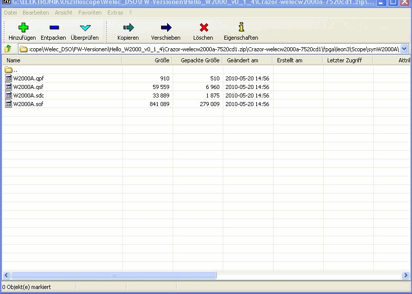
Hi Robert,

Ich habe mal den Source auf eurer Seite herunter geladen und habe unter
Anderem, eine ----W2000A.sof---- ausfindig gemacht(siehe Screenshot)!
Kann diese geflasht werden und brauche ich noch eine sram.bin?

Gruß Michael

EDIT: Jetzt habe ich noch eine sram.bin neueren Datums entdeckt!

...geht da was, mit dem aufspielen(Waverecorder)

noch mal Gruß
Hallo Michael

Michael D. schrieb:
> Ich habe mal den Source auf eurer Seite herunter geladen und habe unter
> Anderem, eine ----W2000A.sof---- ausfindig gemacht(siehe Screenshot)!

Das ist das aktuelle FPGA-Desgin mit dem neuen Speichercontroller.

Eine firmware.bin benötigst du immer noch. Derzeit ist keine aktuelle
auf der Sourceforgeseite. Weder vom Waverecorder noch der Leon-Firmware.

Ich habe heute eine Anleitung für das Aufsetzen der Toolchain unter
Windos geschrieben:
https://sourceforge.net/apps/trac/welecw2000a/wiki/ToolchainWindows

Damit hat sehr schnell ein das ganze aufgesetzt um den Waverecorder als
auch die Leon Firmware zu erstellen.

Grüße Robert
Jetzt sind eine w2000a.bin und der waverecorder.exe auf SF verfügbar.

https://sourceforge.net/apps/trac/welecw2000a/wiki/Leon%20Binaries


W2000A.sof:
http://github.com/Crazor/welecw2000a/raw/master/fpga/leon3/Scope/synW2000A/W2000A.sof
@Bert

Die externe Triggerung steht bei mir als einer der nächsten Punkte auf
der Liste. Zugegebenermaßen habe ich die externe Triggerung noch nie
ausprobiert. Ich meine aber mich erinnern zu können, dass die noch nie
funktioniert hat (weder in den original Welec Versionen und zwangsläufig
auch nicht in den Open Source Versionen die ja von der originalen 1.2
abstammen).

Alle bisherigen Triggeroptimierungen waren nur für den internen Trigger.

Gruß Hayo
Ich habe mal das Batchfile für den Waverecorder angepasst, sonst läuft
der ja nicht an!

Die ---sram.bin--- heißt hier ---w2000a.bin---

Es müsste nur noch der Comport angepasst werden,
in meinem Fall ist das COM 1 mit 115200 Baut.

Jetzt haben wir hier mehrere Waverecorder mit verschiedenen Dateigrössen
zur Auswahl
Ich nehme mal an, das die mit 630kb vom 21.05.2010 die Aktuelle ist ?1?

Gruß Michael
Hallo Michael,
wenn du die zip Datei vom 22.05.2010 meinst, die ist ziemlich auf dem
neuesten Stand. Flimmerfrei und mit Screenshot Unterstützung im BMP
Format.

Mfg,
Kurt
Angehängte Dateien:
-

Leon3_Kanal2_200mV_Div.png
290 KB
Hi Kurt,

ich habe die Files von deinem Link, die da heißt:---22052010.zip---
...da ist auch der Waverecorder drinnen!

Gestern habe ich das neue Leon3 aufgespielt, funzte auch einwandfrei...

...eben hatte ich es noch mal aufgespielt und jetzt hängt sich das DSO
ständig auf und nix geht mehr!
Kann es sein, das da noch Reste im Ram sind und da Konflikte verursacht?

Ansonsten stellt Kanal 2, trotz selbiger Einstellung wie Kanal 1
(200mV/Div) das Signal (ProbeComp)nicht korrekt dar, siehe Foto.

Gruß Michael

EDIT: Die Screenshotroutine arbeitet mit dem Waverecorder? Wenn ja,
wären das die korrekten Parameter für die Batch?

---WaveRecorder -u com1 -b 115200 -n 2 -Capture
Die Drehgeber für scroll, triggerlevel usw sind auch noch etwas
unentschlossen wenn man daran dreht.
Ansonzten schon ganz nett!
Hi,
Betreff Leon3: Kann man die Signale (Nulllinie) nicht verschieben? Beim
Spannungswechsel sind diese zu weit oben, und Kanal 2 zu weit unten,
oder ist das noch in der Mache?

Ich bekomme das mit der Screenshotroutine nicht gebacken, der
Waverecorder geht gleich wieder zu...wie sehen denn die Strings in der
Batchdatei aus?

WaveRecorder -u com1 -b 115200 -n 2 -p Debugger -c Capture
--WFile=screenshot001.bmp---

Ich denke mal, das diese nicht korrekt ist!

Ansonsten ist hier eine super Leistung erbracht worden und möchte an
dieser Stelle mein Lob an die Macher aussprechen!!!

Gruß Michael
Michael D. schrieb:
> Betreff Leon3: Kann man die Signale (Nulllinie) nicht verschieben? Beim
> Spannungswechsel sind diese zu weit oben, und Kanal 2 zu weit unten,
> oder ist das noch in der Mache?

Ist derzeit noch nicht implementiert. Kommt aber noch. Derzeit schauen
wir gerade, dass der DAC funktioniert.

Michael D. schrieb:
> Ich bekomme das mit der Screenshotroutine nicht gebacken, der
> Waverecorder geht gleich wieder zu...wie sehen denn die Strings in der
> Batchdatei aus?
>
> WaveRecorder -u com1 -b 115200 -n 2 -p Debugger -c Capture
> --WFile=screenshot001.bmp---

Der Aufruf ist leider falsch. Das Screenshotkommando ist leider nicht in
der Hilfe. Mea Culpa!

Folgender Aufruf ist richtig:
Waverecorder -u com1 -b 115200 -n 2 -p CPU -c Screenshot -f <filename>

Ich bin derzeit gerade dabei den ganzen Waverecorder umzubauen um die
Bedienung zu erleichten. Dann ist es einfach möglich mit Waverecorder
--screenshot einen Screenshot zu machen.

Grüße aus Österreich
Robert
Hallo Robert,

Folgender Aufruf ist richtig:
Waverecorder -u com1 -b 115200 -n 2 -p CPU -c Screenshot -f <filename>

Na klasse, da kann ich ja lange suchen, trotzdem danke!
Werde das mal testen, wenn ich wieder Daheim bin...

Gruß Michael
ich noch mal,

also ich könnte mit der Stapelverarbeitung leben, wenn alle Commands zur
Verfügung stehen und funktionieren, ist das auch ok!

Noch mal zum Leon3 !
Bei 200mV/Div ist ja, im Vergleich zur jetzigen Software, das Rauschen
enorm niedrig.

Kann es sein, das auch noch nicht alle Spannungsbereiche zur Verfügung
stehen? Geht ja runter bis in den µV/Div Bereich.


Gruß Michael
mike0815 schrieb:
> also ich könnte mit der Stapelverarbeitung leben, wenn alle Commands zur
> Verfügung stehen und funktionieren, ist das auch ok!

Ist schon alles umgebaut. Wird noch getestet. Aber generell wurde es
verwinfacht. Waren einfach zu viele Parameter für einfache Kommandos.

mike0815 schrieb:
> Noch mal zum Leon3 !
> Bei 200mV/Div ist ja, im Vergleich zur jetzigen Software, das Rauschen
> enorm niedrig.

Danke für die Rosen. Gebührt natürlich Alexander!

mike0815 schrieb:
> Kann es sein, das auch noch nicht alle Spannungsbereiche zur Verfügung
> stehen? Geht ja runter bis in den µV/Div Bereich.

Daran wird gerade gearbeitet. Bei langsamen Signalen wird das Signal auf
16-Bit hochgesampelt um auch sehr kleine Spannungen messen zu können.

Grüße Robert
Angehängte Dateien:
-

screenshot001.png
2,3 KB -

screenshot002.png
1,9 KB
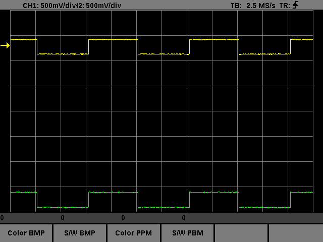
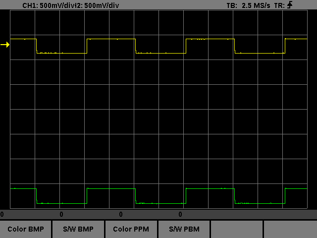
Hallo Robert,

Robert S. schrieb:
> Ist schon alles umgebaut. Wird noch getestet. Aber generell wurde es
> verwinfacht. Waren einfach zu viele Parameter für einfache Kommandos.

verwinfacht?


Die Screenshotfunktion funzt einwandfrei, man kann immer nur einen Shot
machen den man jedes mal manuel umbenennen muß sonst wird der nächste
Shot überschrieben!
Ich habe mal eine Batchroutine gebaut.
Es können damit 10 Shots nacheinander mit fortlaufender Nummer gemacht
werden!
Die Parameter sind Com1 und 115200 Baut.
Wer einen anderen Comport hat(z.B. Com2 oder 3), muß diesen angleichen!
Ein kleiner Beitrag von mir für dieses Projekt.

Der erste Shot ist ohne Filter, der 2. mit eurem HW-Filter.
Da wurde einiges geleistet, unglaublich was da möglich ist!!!

Anbei noch meine gebaute Batch.

Gruß Michael
Michael D. schrieb:
> Die Screenshotfunktion funzt einwandfrei, man kann immer nur einen Shot
>
> machen den man jedes mal manuel umbenennen muß sonst wird der nächste
>
> Shot überschrieben!

schon Behoben. Mann kann in Zukunft einfach mit Waverecorder
--screenshot (defaultname, falls vorhanden wird die nr erhöht) oder mit
--screnshot <filename> erzeugen.

Gruß Robert
Hi Robert,

wie ich sehe, -- http://github.com/Crazor/welecw2000a --

seid ihr weiterhin fleißig am Programmieren vom Leon3.
Wann kann man denn mit einem neuen Testfile rechnen? Für eine Beta ist
es ja wohl noch zu früh.

Gruß Michael
Hi there,

mal wieder was Neues aus der Nios Firmware Ecke. Hier die neue 1.5 mit
einigen Verbesserungen:

- optimierte Flashsicherung für den Configbereich
- neue RMS Berechnung beim Quick Measure

Die neue Routine ist etwas langsamer als die Alte da sehr viel gerechnet
wird. Dafür wird jetzt der Effektivwert beliebiger Signalformen
berechnet
und nicht wie vorher nur für Sinus. Etwas Optimierungspotential in
Sachen Geschwindigkeit wäre da noch wenn man einige Multiplikationen
durch Schiebeoperationen ersetzt, hatte ich aber momentan keine Zeit zu.


For our non german speaking friends:

- optimized flash writing for the config data
- new RMS calculation for Quick Measure

The new routine is a little bit slower because of the additional
calculations. The benefit is that now for every signal form the RMS kann
be measured and not as before only for sinus. The speed may be increased
by exchanging the multiplications with shift operations, but I didn't
had the time for that.

Thanks at this place to Alessandro (Scroky) for the tip with the wrong
RMS calculation.

The download is also available here:

http://sourceforge.net/projects/welecw2000a/


Hayo
Hi to all.
Thank you very, very much Hayo!
I run to try your new gem,Hayo you are really very kind and great!!!
Vielen Dank!!!

Luc
Hi Hayo,

habe eben mal deine 1.5er aufgesetzt und ein bißchen gespielt.
Hast du da was an der Timebase geschraubt?
Die erste Flanke bleibt immer schick an einer Stelle.
Habe gesehen, das der Browser sich da automatisch mit
einpendelt...saubere Sache!
War das bei 1.4 schon der Fall?

Gruß´Michael

Ps. ist dein Mikroskrop inzwischen eingetroffen?
Hi Michael,

ja nach nur 3 Wochen Wartezeit ist es tatsächlich schon eingetroffen.
Nach dem Urlaub lag auf einmal eine Benachrichtigung zur Paketabholung
im Briefkasten. Bei denen geht wohl im Momentalles drunter und drüber
wegen einer IT-Umstellung.

Aber das Teil an sich ist ganz ok muß ich sagen. Macht echt Spaß damit
herumzuspielen. Zur Zeit bastel ich gerade an einem alten Mikroskop
herum und versuche das USB-Mikroskop an das alte Stativ anzubringen um
den Feintrieb nutzen zu können.

Zur 1.5:

Nein ich hab da soweit ich mich erinnern kann nur an den Flashroutinen
und der RMS-Geschichte rumgeschraubt. Wer mal in das changelog
reingesehen hat weiß auch dass ich noch die neue Overlay-Funktion in
Vorbereitung habe, die ist aber noch nicht aktiv - kommt demnächst.


Gruß Hayo
@Luc

I am pleased that You like it - try out the the new RMS function in the
Quick Measure function and enjoy!!

Hayo
Hayo Thanks again!

Davvero mitico ! :)

For the future version, you can add the ability to maintain the
configuration of the trigger even after the ladders used or switches to
USTB?

Bye, Gyppe.
So jetzt bin ich endlich mal wieder dazugekommen, die aktuelle BF
Version zu testen. Der letzte Test ist schon einige Versionsnummern her
und ich muss sagen: seitdem hat sich ordentlich was getan! So gut konnte
man noch nie mit der Kiste arbeiten, Kompliment und danke an Hayo!
Vor allem die Neuigkeiten im Utility Menü haben machen sich positiv
bemerkbar, insgesamt fine ich im Moment außer den nervigen Spikes kaum
etwas auszusetzen.

Viele Grüße
Michael
Hi,

I'm new here, my German knowledge is zero.

I am updating the Welec pages at SourceForge.com and I have several
questions. Is this the right place to post?
I'm sure that your questions will be answered promptly if they are
related to the opensource firmware.
Michael H. schrieb:
> Im sure that your questions will be answered promptly if
> they are related to the opensource firmware.

Hi , well those are actually my first questions, to figure out what
belongs where. Mentioned on the web site are
GUI
Screenshot
DataExport
Remot Control Protocol
USB protocol

Are these related to the opensource firmware?
Hi Jan,

that's correct. The origianal firmware version are not supported by our
project, because they are so terrible buggy, that it makes no sense to
spend any time on it. Some guys here around in the forum and on Source
Forge have developed their own Interface and GUI. The screenshot is
working well, same as the communication protocol for the RS232.The GUI
project is still under construction, I think.

Actual I'm developing and testing the USB interface. First success is
that the WELEC PC-Software now communicates with the 1.2.BF.1.6 version
which is not released until now.

Kind regards

Hayo
Ok Leute,

noch mal auf Deutsch, zur Zeit bin ich gerade an den USB-Routine am
Rumdengeln. Erster Erfolg: Die Kiste spricht wieder mit der WELEC
PC-Software. Allerdings sind da noch so viele Bugs drin, dass es wohl
noch etwas dauert bis ich Euch das zumuten kann. Einige Bugs werde ich
nicht beseitigen können, da diese auf der Seite der PC-Software liegen.
Da sich die tolle Software darüber ausschweigt welcher Version sie sich
angehörig fühlt, weiß ich nichtmal ob meine die Aktuellste ist (Größe
1168 k).

Desweiteren implementiere ich parallel dazu ein neues USB
Kommunikationsinterface, auf dem auch die bestehenden Programme wie
screenshot und GUI aufsetzen können. Beispielprogramme zur Ansteuerung
lege ich dann bei.

@Michael

Und? ist die Mikroskopsoftware bei Dir angekommen - und läuft sie?

Gruß Hayo
Ok, what I am trying to do is to clarify the situation for
newbies/newcommers: which parts are available and suitable for end
users, which are in the developers toolboxes.

I think I will make something like a table with three columns, one for
the original Welec firmware and codes 8for comparison), one for the open
source firmware (does it have a NAME? the Hayo firmware?) and the third
being the Leon3 development.

I would try to maintain an overview of what works, what is compatible,
alpha, beta, buggy, working or whatever. Whatever is considerd ready to
run by a normal owner with some PC knowledge would be the the top
priority for me.

Makes sense?

When the 1.2.BF.1.6 has USB support, there is not yet any end user
software to hook up to that USB on the (PC) side?
Hi Hayo,

wenn du die Software von Welec's Seite meinst, das ist die einzige
Version, die dort existiert!
Die hatte bei mir nur einmal gefunzt, beim nächsten Start, ist die dann
ständig stehen geblieben, danach hab' ich es gelassen, bevor ich einen
Hammer in den Bildschirm geschmissen hätte!

Ui, du schraubst am USB? Da bin ich mal gespannt!
Mich würde mal interessieren, was so die Huckepackplatine macht und ob
der Prototyp schon am laufen ist?!?

Mikrosoftware:
Die habe ich bekommen, hatte dir eine Mail mit einem fetten Dank
geschickt!
Werde ich evtl. Morgen testen, mußte heute lange Arbeiten.

Gruß Michael
One visitor on the SourceForge site wrote about half a year ago a very
relevant question from a newcommer:

"A lot of files and info here but what does the latest firmware contain?
Functional FFT? Is the fw fully functional so I can use it instead of
the original fw?"

Can someone make short summary here that we can also use in the wiki?
Hi Jan, it's quite easy: no functinoal firmware is available. :-(

There are two ways at the moment and a half one. Best of all will
be the Leon-Design. But it is still not working for real use, as
far as i know. The developement of firmware for this one is just
starting.

Forget the original firmware of Welec, it is not usable anyway.

The original hardware-design is supportetd by 2 slightly
different firmwares. One ist the BF-version supportetd mainly
through Hayo W (blueflash) and this might be the most
sophisticated version. The last revision of this firmware
should be the starting point for new users.

The second firmware for the original hardware-design is the
so called OS-version at source-forge. But this is somewhat outdated
and seems to be not longer supported. Most of it's developers
can be asked here or at source-forge, they still are online. This
firmware is worth aa try, too.

Kind regards, Guido
Jan F. schrieb:
> Ok, what I am trying to do is to clarify the situation for
> newbies/newcommers: which parts are available and suitable for end
> users, which are in the developers toolboxes.

Good idea I think. I thought about an user manual belonging to the open
source version. But in last time there where too much changes to write a
valid manual.

> I think I will make something like a table with three columns, one for
> the original Welec firmware and codes 8for comparison), one for the open
> source firmware (does it have a NAME? the Hayo firmware?) and the third
> being the Leon3 development.

The original Firmware is not usable for anything, but nevertheless it
may be interresting to have a comparison.

> I would try to maintain an overview of what works, what is compatible,
> alpha, beta, buggy, working or whatever. Whatever is considerd ready to
> run by a normal owner with some PC knowledge would be the the top
> priority for me.

The 1.2.OS.0.x versions are basing on older 1.2.BF.0.x versions and
occasionally where nearly identical because of source exchange between
both. The versions with the .0.x versions are beta versions, what means,
that they where better than the original firmware, but there where many
functions which where still under construction or not tested properly.

While the last OS-version is a little bit older and just in beta status,
I went on with developing the BF-versions and reached the stable release
status (BF.1.x) That means that most functions are working well and are
usable for anyone.

There are still some little bugs and some functions (as USB and FFT) are
under construction, but I think that's the normal way of software
developing.

Most important is the support we (the guys here and I) can offer to any
user who has problems with his DSO. If the problem is solvable it will
be solved as soon as possible.  And if it is not solvable - it may take
a little bit longer ;-)

> Makes sense?
indeed
> When the 1.2.BF.1.6 has USB support, there is not yet any end user
> software to hook up to that USB on the (PC) side?

In the first step I try to support the original PC-Software which was
supplied by WELEC/Wittig and to repair the interface communication which
is a relic of the WELEC 1.2 Firmware on which all open source
development bases.

Simultaneous I am developing an own communication protocol for an own
open USB-Interface. For this I will supply some templates under Linux
and Windows which can be used by other developers to create new
applications.


Kind regards

Hayo
I started making the overview table at SourceForge. Please send me
comments and additions! My idea is to place most links that are now
further down on the page, into the table later.

- Is the 1.2.BF.0.x worth mentioning there?
- Whatever the shortcomings, the latest 1.2.BF.1.X is the "recommended"
version?
- I am also updating the pages on Screenshot, GUI etc, one at a time....
Jan F. schrieb:
> I started making the overview table at SourceForge. Please send me
> comments and additions! My idea is to place most links that are now
> further down on the page, into the table later.

Good idea

> - Is the 1.2.BF.0.x worth mentioning there?

that are the older beta versions. Details can be seen in the change log
which is supplied with every new version. Those versions are only used
for comparing when searching for mystery failures in newer versions
which didn't appear in earlier versions.

> - Whatever the shortcomings, the latest 1.2.BF.1.X is the "recommended"
> version?

At this time I would say yes, but maybe the OS-Version will be brought
up to date in future...

> - I am also updating the pages on Screenshot, GUI etc, one at a time....

Until now there is nothing new (as far as I know), but be aware that
there are also existing two screenshot versions with different handling.
The actual BF-versions are supporting both! The OS-Version is a little
bit faster, because of an more efficient compression algorithm.

One of the first USB applications I'm planning to create, is an
USB-screenshot version, which may be much faster than the RS232
versions.

In the next time I want to experiment on a Visual C++ GUI to use the USB
Interface. This will be available as template as well.

Kind Regards

Hayo
I am now pointing the SF BUTTON to BF.1.6 (as I did not think it was
appropriate to have developers files there). I saw the stats of 150
weekly downloads and I do not think all those are developers? I could
change the text to "Recommended Firmware Version" and let "you guys"
decide which one this is. I am too much on the outside to have an
opinion and I do not want to cause any friction or whatever. Just trying
to help newcomers get moving.

If someone goes to SF, searches, downloads the latest firmware package
they should imo be helped to the right web pages, to the uploader apps.
So I'd recommend a readme file with a link to the first page of the wiki
and to the SF forum. I will make links onward from there. OK?
SF repository; somehow I can change everything except the PC-Software
subdirectory. So I created a new one named PC software and uloaded the
files there. Can someone please delete the PC-Software library. I do not
have the rights there...
SF: I am updating the Screenshot wiki page. Unfortunately there is no
review system so I am editing the live version.

Some questions for the wiki page

- There is a firmware softbutton on the scope for BF / OS but with
1.2.BF.1.5 I only get screenshot 0.91 working with the OS mode? Normal?

- There are four soft buttons on the scope, but it seems ascii / csv and
bitmap mode are actually controlled by Screenshot? Does the FV actually
toggle between the four modes and does screenshot handle them all?

- I ran the exe on XP/32 Does it run on other OS too?


(- I know this is an early version but I miss some communication
verification both from PC and firmware (ie screenshot saying, "Scope
connected" when started and scope saying "Transferring" when softbuttons
have been pushed. Now I had some trouble with comms an never new if it
was dead or alive.)
Jan F. schrieb:

Hi Jan,

> SF: I am updating the Screenshot wiki page. Unfortunately there is no
> review system so I am editing the live version.

There is an nice little button which says: "Preview Page" - I think,
you can estimate it's meaning.

>
> Some questions for the wiki page
>
> [BF.1.5]

For your information about the OS series of the firmware:

 in sommer last year branadic discovered, that the DSO produces some
ringing on higher frequencys (a few MHz) and amplitudes. Falk discovered
that this was caused by an wrong filter setting in the firmware.

This error is only corrected in the OS series of the firmware.

For the screenshot you must have a corresponding version of screenshot
to the firmware. So screenshot 0.90 will not work with OS 0.91 or
0.92(a).

(For history: the 0.92a was a bugfix to 0.92)

Kind regards,

    rowue
Rolf W. schrieb:
> Jan F. schrieb:
>
> Hi Jan,
>
>
>  in sommer last year branadic discovered, that the DSO produces some
> ringing on higher frequencys (a few MHz) and amplitudes. Falk discovered
> that this was caused by an wrong filter setting in the firmware.
>
> This error is only corrected in the OS series of the firmware.

That's not correct! In the BF-versions You have the option to choose
between different filter settings -> hardware menu->ADC Setting

Hayo
Jan F. schrieb:

> - There is a firmware softbutton on the scope for BF / OS but with
> 1.2.BF.1.5 I only get screenshot 0.91 working with the OS mode? Normal?

Maybe that some interfaces (USB->RS232) may cause some problems with one
of the versions.

> - There are four soft buttons on the scope, but it seems ascii / csv and
> bitmap mode are actually controlled by Screenshot?

The BF-version is controlled by the scope, so it can be started with few
parameters. The OS-version is controlled by parameters on the PC-side.
So the Softbuttons have limited function here.

> - I ran the exe on XP/32 Does it run on other OS too?
Linux is supported as well

> (- I know this is an early version but I miss some communication
> verification both from PC and firmware (ie screenshot saying, "Scope
> connected" when started and scope saying "Transferring" when softbuttons
> have been pushed. Now I had some trouble with comms an never new if it
> was dead or alive.)

The BF-version informs You via console messages when it is receiving a
screenshot.

Hayo
In der Mai-Ausgabe der Elektronikpraxis, in Teil 3 zu Grundlagenwissen
Oszilloskop nachzulesen:

Zitat:
"Die beiden Triggermodi

Der Triggermodus bestimmt, ob das Oszilloskop ein Signal auf der
Grundlage eines Signalzustands darstellt oder nicht. Gängige Triggermodi
sind:

* Normalmodus: Das Oszilloskop erzeugt nur dann eine Darstellung des
Signals, wenn das Eingangssignal den Triggerpunkt erreicht. Anderenfalls
ist der Bildschirm leer oder auf dem zuletzt erfassten Signal
eingefroren.

* Auto-Modus: Im Auto-Modus stellt das Oszilloskop auch dann ein Signal
dar, wenn kein Trigger anliegt. Wenn kein Signal vorhanden ist, triggert
ein Zeitgeber im Oszilloskop die Ablenkung. Dies gewährleistet, dass die
Anzeige nicht ausgeblendet wird, wenn das Signal keinen Trigger
auslöst."

Die drei Artikel zum Thema: Grundlagenwissen Oszilloskope

Teil 1:
http://www.elektronikpraxis.vogel.de/themen/hardwareentwicklung/messtechnik/labormesstechnik/articles/252618/

Teil 2:
http://www.elektronikpraxis.vogel.de/themen/hardwareentwicklung/messtechnik/labormesstechnik/articles/255168/

Teil 3:
http://www.elektronikpraxis.vogel.de/themen/hardwareentwicklung/messtechnik/labormesstechnik/articles/258115/

Wollt ich nur beitragen, da es dazu ja mal eine Diskussion gab.
Mr. Neumalklug schrieb:

> Wollt ich nur beitragen, da es dazu ja mal eine Diskussion gab.

Klasse, das ist ein guter Tip. Eigentlich könnte man das in ein Manual
für das WELEC mit aufnehemen. Denn in dieser Preisklasse sind bestimmt
etliche Neueinsteiger unter den Besitzern.

Gruß Hayo
Hayo W. schrieb:
> The BF-version is controlled by the scope, so it can be started with few
> parameters.

I use BF.1.6 and it seems both screenbuttons and commandline works with
Screenshot 0.91 but it worked with the softbutton set to OS, not when
setting it to BF (USB-serial cable)

Anyway, the wiki page is updated now. Let me know if additions / changes
are needed.
...wo hat denn der Jan F. die BF 1.6 her, hab' ich da was verpasst???

Gruß Michael
Thanks Rolf and others,

What I meant by review was to be able to have you look at a version
before posting it. I am aware of the Preview.

Is there a relation also between the BF version and screenshot version?
I'm just trying to get rid of the frustrations these things may cause
for end users. I have added a footnote about versions but will make it
clearer.
Jan F. schrieb:

> Is there a relation also between the BF version and screenshot version?
> I'm just trying to get rid of the frustrations these things may cause
> for end users. I have added a footnote about versions but will make it
> clearer.

to avoid such problems, I distribute the corresponding PC-addons with
the released versions in one package.

It is recommended to use those versions from the package. Maybe other
versions are working as well but it is not tested.

@all

noch mal in Deutsch:

Um Kompatibilitätsprobleme zu vermeiden, lege ich die passenden
PC-Anwendungen immer mit ins freigegebene Downloadpaket. Kann sein, das
auch andere Versionen funktionieren, aber das habe ich nicht getestet.


Kind regards / Gruß

Hayo
Hallo Hayo (Hallo Leute)

Möchte da mal ein Programm erwähnen, dass ich mir vor kurzem gekauft
habe (99,-)
Es heißt "ProfiLab-Expert 4.0"  von Abacom
http://abacom-online.de/html/profilab-expert.html

Ich bin echt begeistert davon!!!!

Man kann damit sehr viele Messgeräte an den PC anbinden und dort dann
darstellen lassen. z.B. Multimeter oder USB-Messkarten und vieles mehr.
Man hat dann eine Grafische Oberfläche mit z.B. Zeigergeräten,
XY-schreiber u.s.w.
Die einzelnen Funktionen und Abhängigkeiten voneinander kann man einfach
per Symbole definieren und programmieren.
Das beste ist noch, man kann dieses Programm dann compilieren und hat
dann eine eigenes Lauffähiges Programm!

Das Programm unterstützt sehr viel Hardware! Eigentlich fast alles was
über RS232, parallel oder USB geht.

Meine Idee wäre nun die, dass man das Welec-DSO vielleicht auch an
dieses Programm anbindet.
Es gibt da auch ein Forum:
http://forum.abacom-online.de/phpBB3/
und soweit ich mit gelesen habe, ist diese Firma auch immer bestrebt,
neue Hardware in Ihr Programm aufzunehmen.
Unterstütze Hardware z.B. hier:
http://abacom-online.de/html/hardware_de.pdf


Nur mal so eine Idee, weil Du schon an der USB bastelst.

Eigentlich war es ja meine Hoffnung, das aus dem DSO vielleicht mal ein
bisschen ein Digital Analyzer wird. Aber inzwischen habe ich mir einen
eigenen kleinen gekauft...

Aber man könnte z.B. mit dem Profilab noch immer Messwerte darstellen
lassen , oder zu frei definierten Zeiten Messwerte abrufen und vieles
mehr...

Nur mal so eine Anregung :-)

l.G. Roberto
Hmmh,

von Linux steht da aber nix. Wäre es nicht die Aufgabe von
abacom für zahlende Kunden das Welec in die Reihe
unterstützter Geräte aufzunehmen?

Gruß, Guido