-
Artikel
Demo Gilbertzelle
für Zweig I A2 bleibt nichts übrig. Bei negativem U A schaltet T2 durch, womit der gesamte Strom von I Senke über den Zweig I A2 fließt. Nun hängt an beiden Zweigen je ein weiterer Differenzverstärker, der allerdings
Sägezahnspannung S an den Eingang E des Symmetrierverstärkers angeschlossen. Dessen Ausgangsspannungen A1 bzw. A2 sollten in etwa die gleiche Amplitude aufweisen und jeweils einen Stellbereich von 120 mVss oder etwas mehr erreichen, wenn A1 und A2 mit den Eingängen A1 und A2 des Mischers verbunden sind.
-
 Bild
Bild
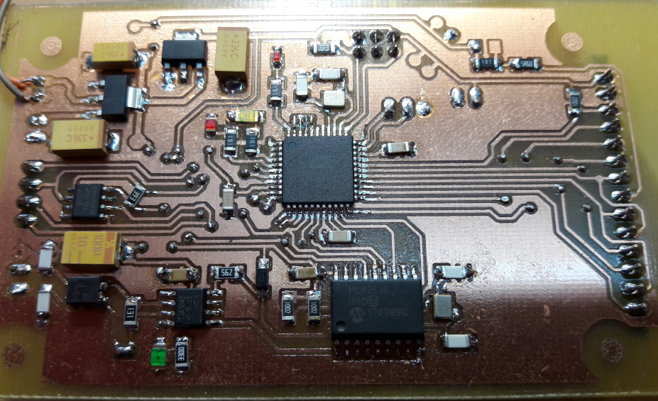
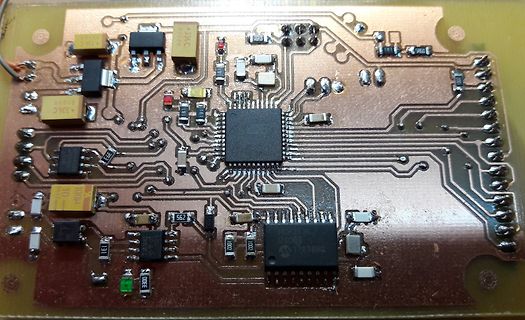
Bestückte Leiterplatte mit integriertem Schaltkreis
A336C, 1004, 562, 1022, 172789Q, 101, 102, 103, 104, 105, 106
-
Thread
Wie geht das Abstandsradar`, auf welcher Frequenz? Mit Signatur?
Shahriar hat mehrere interessante Videos zum Thema Automotive Radar, z.B. TSP #101 - Tutorial, Experiments & Teardown of a 77GHz Automotive FMCW Radar Module 80.535 Aufrufe vor 9 Jahren https://www.youtube.com/watch?v=8af9YVIqhRk
dagegen. Weiterführende Links: TI Radar Academy https://dev.ti.com/tirex/explore/node?node=A__AXNV8Pc8F7j2TwsB7QnTDw__RADAR-ACADEMY__GwxShWe__LATEST TI Whitepaper Radar Interference https://www.ti.com/lit/an/swra662a/swra662a.pdf?ts=1784097686783
-
 Bild
Bild
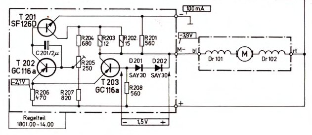
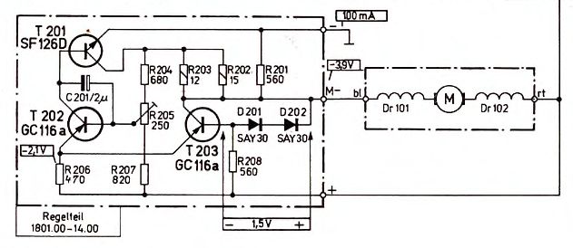
Schaltplan einer Motorsteuerung
T 201 SF126D, C 201/2µ, R 204 680, R 203 12, R 202 15, R 201 560, 100 mA, -3,9V, T 202 GC116a, R 205 250, T 203 GC116a, D 201 SAY30, D 202 SAY30, R 206 470, R 207 820, R 208 560, -2,1V, Dr 101, M, Dr 102, bl, rt, Regelteil 1801.00-14.00, 1,5V
-
Thread
PV Simulator für Batteriebetrieb von Hoymiles & Co
- Standard Mosfets der 2mOhm-Klasse im SO8-Gehäuse - Kühlung nicht nötig - 100µH Drosseln (TLC/10A-101M-00) für je 8,50€ AD=70mm 25dick - MLCC 6x 10µF/100V quer über die Brücke - antiparallel geschaltete Opto-Gatetreiber zur 1-Pin Steuerung Die GaN-Variante bei 250Khz sähe so aus: - EPC23111
sehr professionell. Dein erster Prototyp ist ja ziemlich wuchtig (laut Mouser wiegt allein ein TLC/10A-101M-00 ca. 200 g). Verstehe, dass Du anstatt Schuhschachtel- lieber Zigarettenschachtelgrösse anstrebst ;) Der epc23111 (bzw. epc23104, da günstiger?) würde den Aufbau natürlich vereinfachen.
-
Thread
Alternativer SSB-TX Ansatz => QRP
testhalber zwei sehr einfache mit je zwei Koeffizienten ausprobiert: [pre] % Branch I (In-Phase) aI1 = -0.735495; aI2 = 0.459346; % Branch Q (Quadrature) aQ1 = -0.152135; aQ2 = 0.855073; [/pre] An bei das Ergebnis des Tagesschau-Testsignals nach polarer SSB-Modulation und sync. Demodulation
Jörg W. schrieb im Beitrag #8061888: > Dürfte eher A3E als J3E gewesen sein. Interessanter Link. Aber A3E kann es nicht gewesen sein. Zitat [pre] 12 Fernsprechkanäle 300 Hz – 3400 Hz werden über zwei Amplitudenmodulationsstufen frequenzmäßig hintereinander
-
 Bild
Bild
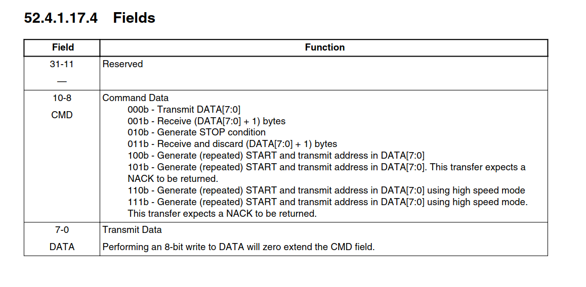
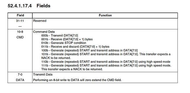
Tabelle mit Registerfeld-Definitionen
and discard (DATA[7:0] + 1) bytes 100b - Generate (repeated) START and transmit address in DATA[7:0] 101b - Generate (repeated) START and transmit address in DATA[7:0]. This transfer expects a NACK to be returned. 110b - Generate (repeated) START and transmit address in DATA[7:0] using high speed mode
-
 Bild
Bild
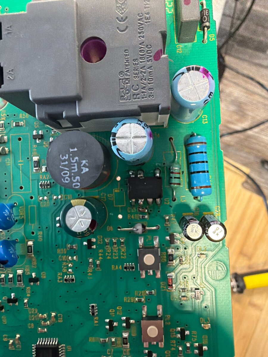
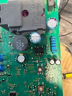
Nahaufnahme einer bestückten Leiterplatte
1A 2A R.C. SERIES 1-1/2A 10/6A 250VAC 3-8 10mA 5VDC KA 31/09 R56 Q5 R48 C11 C16 R42 C17 C15 U2 L3 C13 R46 C20 R40 R39 C10 R37 R44 R33 R23 R24 R32 R28 R29 R41 R43 R42 R62 R63 R64 R65 R66 R67 R68 R69 R70
-
Thread
Gibt es Kühl-Gefrier-Kombis mit Rotationskolbenverdichter?
Inverter, die haben nicht die hohe Anlaufleistung konventioneller Kompressoren. Anlauf/Betrieb 24V 101N0300: 12A/3A, 101N0400 3A/3A
schlappe 80 Watt genehmigen soll. Das hält ihn nicht davon ab sich beim einschalten mal eben >10A zu genehmigen. So ca 3A würden ihm reichen. Ntc oder Vorwiderstand als 'Quick & Dirty' Lösung. Hier schafft es ein 300W Wechselrichter mit einem 750 Inverter ihn mit 2Sekunden Rampe hoch zu fahren.
-
 Bild
Bild
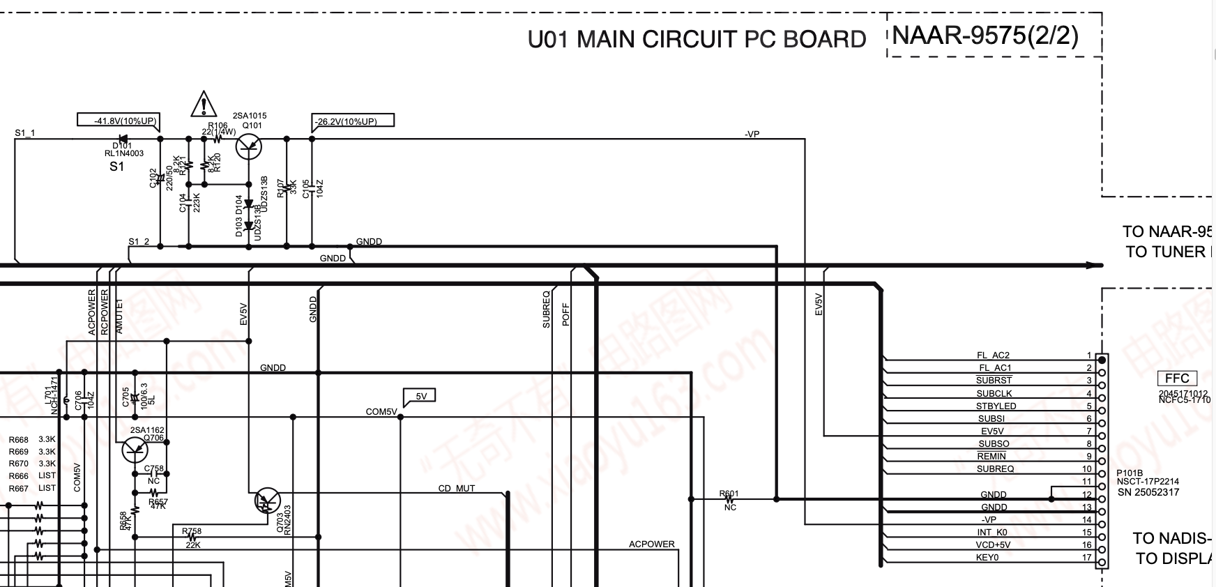
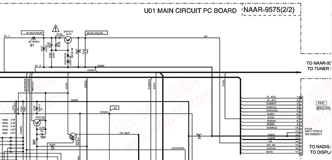
Schaltplan einer Hauptplatine
U01 MAIN CIRCUIT PC BOARD NAAR-9575(2/2) -41,8V(10%UP) 25A1015 R1106 Q101 -26,2V(10%UP) S1_1 D101 RL1N4003 S1 251 38 C202 22K Q101 10AZ C104 R107 D101 Q251 1.2 GNDD GNDD SUBREQ POFF EV5V FL AC2 FL AC1 SUBRST FL AC1 SUBCA 4 STBYLED 5 SUBSI 6 EV5V 8 SUBSEQ 9 REMIN
-
 Bild
Bild
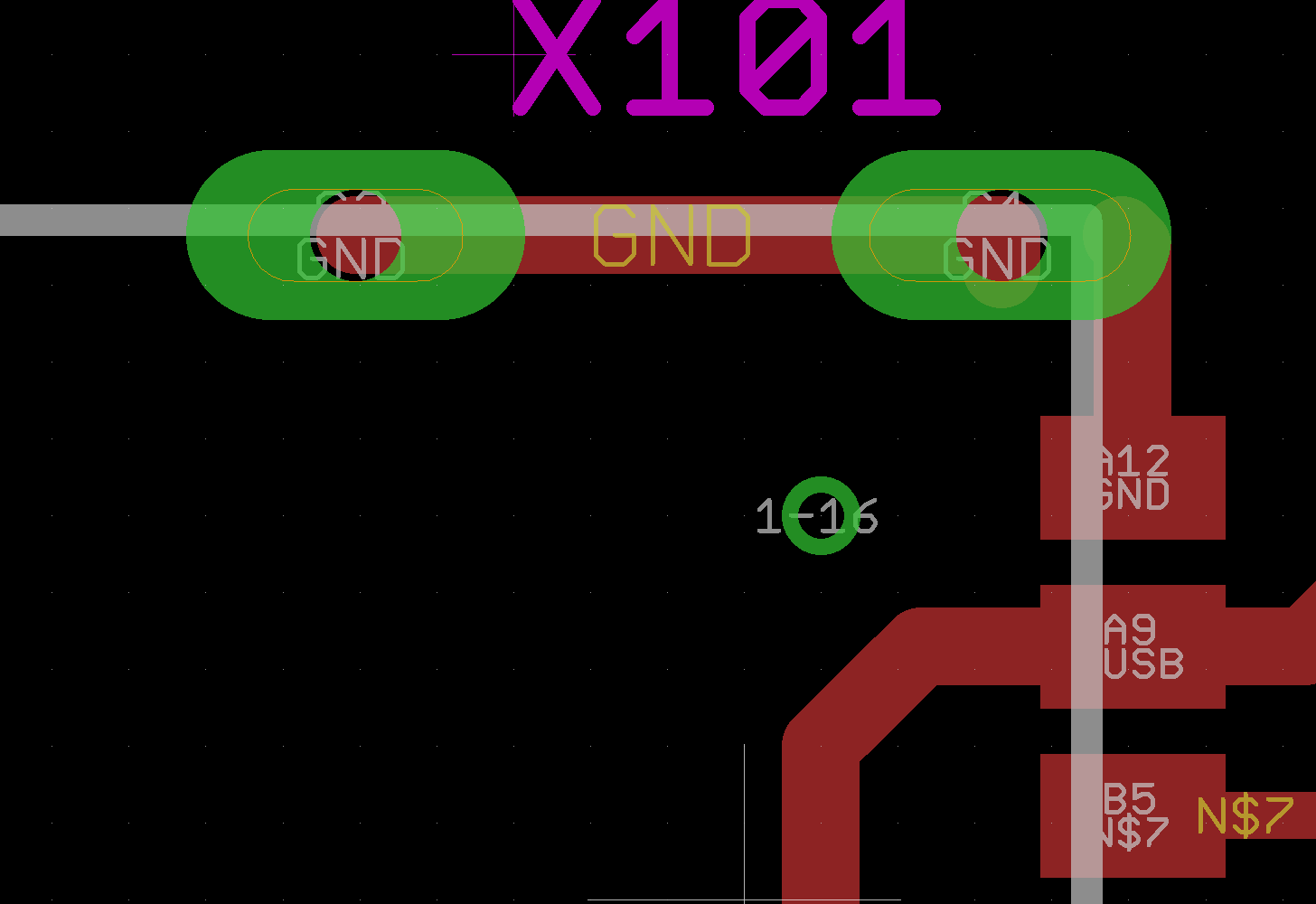
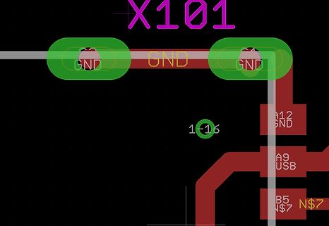
Ausschnitt eines PCB-Layouts
X101 GND GND GND 1-16 A12 GND A9 USB B5 N$7 N$7
-
Thread
# Hameg HM 8030-3 klirrfaktor zu hoch
beiden Potis im Schaltungsteil "signal shaper" zu sehen? Was sollen die wohl tun? Eben. Die sind u.a. für den klirrfaktorabgleich. Ohne geeigentes Messequipment solltest Du eh nicht dran rumdrehen. Wenn doch: Das sind Deine Abgleichpunkte. Wenn Du nun nach Anleitung fragst: Solange justieren, bis der
Einspruch Euer Ehren: Das Gerät hat 14 Trimmer (VR101-VR114). Viele davon beeinflussen sich gegenseitig. Seite 4 von 15: Maintenance The most important characteristics of the instruments should be periodically checked according the instructions provided
-
 Bild
Bild
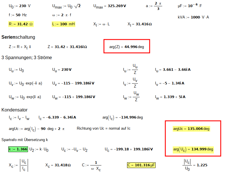
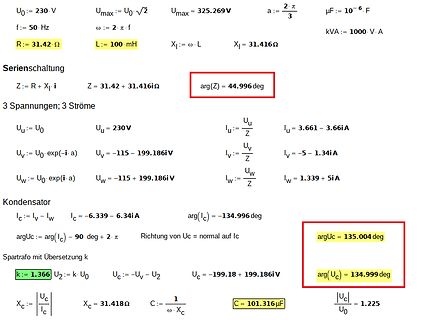
Mathematische Berechnungen zu einer Serienschaltung
Umax := U₀ √2 Umax = 325.269 V R := 31.42 Ω L := 100 mH Xl := ω · L Xl = 31.416 Ω kVA := 1000 V · A Serienschaltung Z := R + Xl i Z = 31.42 + 31.416i Ω arg(Z) = 44.996 deg 3 Spannungen; 3 Ströme Uu := U₀ Uu = 230V Iu := U/Z Iu = 3.661 - 3.66i A Uv := U₀ exp(-i a) Uv = -115 - 199.186i V Iv := Uv/Z Iv = -5 - 1.34i A Uw := U₀ exp(i a) Uw = -115 + 199.186i V Iw := Uw/Z Iw = 1.339 + 5i A Kondensator Ic := Iv - Iw Ic = -6.339 - 6.34i A arg(Ic) = -134.996 deg argUc := arg(Ic) - 90 deg + 2 π argUc = 135.004 deg Richtung
-
Thread
E Motor mit fertiger Achse
-1418-n-elektro-antrieb-dc-motorsteuerungachse-buerstenlos-350-750w-48v-diffirentialgetriebe.html#/101-mc-mc_350w_48v sg Sepp
Haftpflichtversicherungspflicht, Fahrerlaubnispflicht --> Mindestalter. Das Thema kommt immer wieder, siehe u.a. hier: https://www.mikrocontroller.net/topic/384822#4937650 (Link ist jetzt hinter Bezahlschranke)
-
 Bild
Bild
Screenshot eines CAN-Bus-Traces in PCAN-View
Zykluszeit Anzahl Trace PCAN-USB Empfangen 082h 01 00 00 00 360,1 5 193 00 00 80 81 00 00 01 01 492,0 1440 101h 00 1B 00 12 24 A0 07 492,0 1440 141h 0E 8E FC 8F C0 00 A0 25 492,0 1440 181h 15 00 16 00 09 00 A0 2A 492,0 1440 1C1h 02 00 B4 FF 56 56 A0 98 492,0 1440 201h A1 8F 9F 0F 9F 0F 9F 9F 2961,1 240 241h 99 0F 9A 0F FC 8F 0E 0E 2960,7 240 281h F8 0F 99 8F 9F 0F 98 0F 2960,9 240 2C1h 99 8F A1 0F 00 C0 00 C0 2960,6 240 301h 15 15 15 16 16 00 00 2960,9 240 381h 00 50 ED 00 00 00 D0 63 987,7 720 3C1h A5 D9 27 32

-
 Bild
Bild
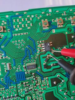
Nahaufnahme einer bestückten Leiterplatte mit Messspitze
ULN2003A, K410, TNV56AC, 261300, 1130, 123, 122, 121, 120, 119, 118, 117, 116, 115, 114, 113, 112, 111, 110, 109, 108, 107, 106, 105, 104, 103, 102, 101, 100, 99, 98, 97, 96, 95, 94, 93, 92, 91, 90, 89, 88, 87
-
 Bild
Bild
Nahaufnahme einer Leiterplatte mit elektronischen Bauteilen
TH101 EPOMC-05 2427C2 CHINA OMRON G5RL-1A-LN 12V DC 12A 50VAC IND TQC 4 19 SK100 VA101 T12A H 250V F100 LB105 LB101 CY101 CY102 Y101
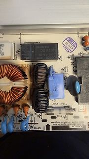
-
 Bild
Bild
Nahaufnahme einer Leiterplatte mit elektronischen Bauteilen
TH101 EPOMC-05 2427C2 OMRON G5RL-1A-LN 12V DC 12A 50VAC CHINA IND TQC 4 19 SK100 VA101 T12A H 250V F100 LB105 LB101 CY101 CY102
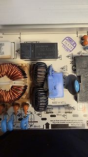
-
Thread
Lunar Landing Game für Arduino
Wenn jemand noch Interesse an Programme aus der Steinzeit der Computerei hat: 101 BASIC Computer Games by David H. Ahl, 1978. Die Seite mit dem Lunar Lander findet man unter https://archive.org/details/ahl-1978-basic-computer-games/page/106/mode/2up
seiner Datenschutzerklärung zusichert. https://www.mikrocontroller.net/articles/Datenschutzerkl%C3%A4rung#Logfiles_/_Serverdaten
-
Thread
Schuko Alternative für 3,5kW Gesperrt
Und tatsächlich ist diese "Ladesteckdose" auch keine besondere Steckdose, der Einsatz hat die Nummer 101.6407A.G von Scame, das Besondere ist halt nur, dass diese mit dem grünen E-Auto Aufkleber ausgestattet ist. Nun denn.... hätte man ohne Aufkleber auch für die Hälfte kaufen können ;-)" Also irgendein
2kW nur mit Festanschluß auszuführen ist. ach und wozu gibt es CEE Stecker und Kupplungen für 16A, 32A, 64A und 125A? Ich habe die durchaus öfter ohne Festanschluß gesehen.
-
Thread
LTDZ Mac Analyzer
: - Port: /dev/cu.usbserial-xxxx - Baudrate: 57600 - Wake: 8F 76 → Antwort 77 - Sweep: 26-Byte-a-Paket - 101 Punkte → 404 Bytes Antwort - Decoding: u16pair Hinweis: Das Projekt ist aktuell ein schneller experimenteller Prototyp. Vibe-coded. Es funktioniert bei meinem Gerät, aber ich habe noch
-
Thread
CAN-Bus Analyse
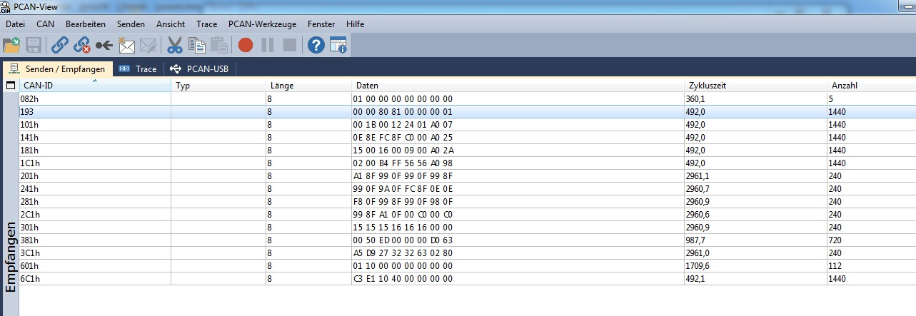
0F 41 00 14 31` - `183h`: `12 00 13 00 05 00 14 69` - `1C3h`: `00 00 18 00 58 58 14 5A` - `383h`: `B7 50 ED 00 00 00 0A B0` - `6C3h`: `C3 E1 10 40 00 00 00 00` ### Gruppe für „Kanal 1“ - `0C1h`: `01 00 00 00 00 00 00 00` - `101h`: `00 01 00 00 00 01 1F 76` - `141h`: `98 0F 9C 0F
**langen Bitfeldern / Zell-Balancing / Fehlerbitmap** aus - `202h`: `A1 0F A1 0F A1 0F A1 0F` - `242h`: `A0 0F A1 0F A1 0F 9F 0F` - `282h`: `A1 0F A1 0F A0 0F A1 0F` Das sind je vier 16-bit Werte um **3999–4001 mV**. Das könnte sehr gut sein: - **vier Einzelzellspannungen
-
 Bild
Bild
Elektronische Bauteile auf einer Leiterplatte
C102 EL31 EL33 ECQUA684 275V~ X2 M 276702 CHINA OMRON G5RL-1A-LN 12V DC 12A 250VAC T12A H 250 F101 RL101 VA101 EL11
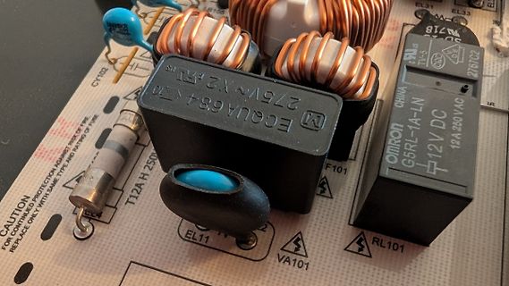
-
 Bild
Bild
Innenansicht einer roten Leiterplatte mit Bauteilen
KC6 KS-01 94V0 E210448 P2G04503 Q13A R30 R31 R32 R33 R34 R35 R36 R37 R38 R39 R40 R41 R42 R43 R44 R45 R46 R47 R48 R49 R50 R51 R52 R53 R54 R55 R56 R57 R58 R59 R60 R61 R62 R63 R64 R65 R66 R67 R68 R69 R70 R71 R72 R73 R74 R75 R76 R77 R78 R79 R80 R81 R82 R83 R84 R85 R86 R87 R88 R89 R90 R91 R92 R93 R94 R95 R96 R97 R98 R99 R100 R101 R102 R103 R104 R105 R106 R107 R108 R109 R110 R111 R112 R113 R114 R115 R116 R117 R118 R119 R120 R121 R122 R123 R124 R125 R126 R127 R128 R129 R130 R131 R132 R133 R134 R135 R136 R137 R138 R139 R140 R141
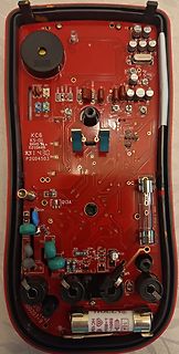
-
 Bild
Bild
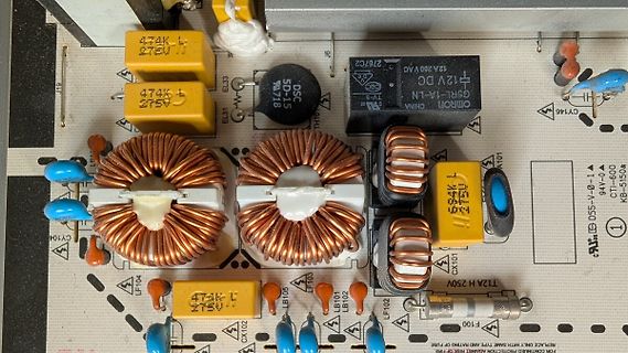
Nahaufnahme einer bestückten Leiterplatte mit Spulen und Kondensatoren
474K, 275U, EL33, SD-15, 718, 12V DC, 12A 260 VAC, Omron, G5RL-1A-LN, CY146, 474K, 275U, CY104, LF103, LB105, LB101, LB102, LF102, T12A H 250V, F100, CX102, CX101
-
 Bild
Bild
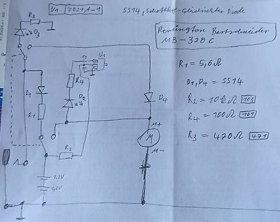
Handgezeichneter Schaltplan eines Remington Bartschneiders
U1 7021A-1 SS74, Schottky-Gleichrichter Diode Remington Bartschneider MB-328 C R1 = 5,6 Ω D1, D4 = SS74 R2 = 10 kΩ 103 R4 = 700 Ω 101 R3 = 470 Ω 471 U1, R3, D3, D1, R1, R4, C1, D4, R2, M+, M-, 1,2V, 1,2V
-
 Bild
Bild
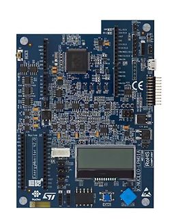
ST Nucleo-LPM01A EnergyMonitor V2.0 Entwicklungsboard
CN4 IOREF NRST 3V3 5V GND AG A1 A2 A3 A4 A5 A6 A7 A8 A9 A10 A11 A12 A13 A14 A15 A16 A17 A18 A19 A20 A21 A22 A23 A24 A25 A26 A27 A28 A29 A30 A31 A32 A33 A34 A35 A36 A37 A38 A39 A40 A41 A42 A43 A44 A45 A46 A47 A48 A49 A50 A51 A52 A53 A54 A55 A56 A57 A58 A59 A60 A61 A62 A63 A64 A65 A66 A67 A68 A69 A70 A71 A72 A73 A74 A75 A76 A77 A78 A79 A80 A81 A82 A83 A84 A85 A86 A87 A88 A89 A90 A91 A92 A93 A94 A95 A96 A97 A98 A99 A100 A101 A102 A103