th a n o r e q u a l 40 to 1 x 10 (HZ)* • 50 S en d s th e co rn x n an d to tu rn th ed a ta k n o bc o u n te rc lo c k w is e fo r 1 s te p o f FINE. 60 R e tu rn s to lin e N o . 3 0 . 70 B ra n c h e s to lin e N o . 1 0 0 w h e th e re a d d a ta is e q u a .L to 1 x 10⁹ (Hz). 80 S e n d s th e
B5 TD-SCDMA B34/B39 Not supported Not supported EVDO Not supported Not supported Not supported CDMA BC0 Not supported BC0/BC1 GSM 900/1800 900/1800 850/1800 GPS L1 Supported Supported Supported Using advanced highly integrated design, SLM750 integrates RF and baseband on a piece of PCB which has functions
tatsächlich hat es die bei mir auch erwischt. Momentan hätte ich in der Schublade eine Auswahl an BC140/141 bzw. BC160/161. Wenn ich den Text richtig verstanden habe, muß man da ein Paar mit möglichst gleicher Stromverstärkung aussuchen? Vermutlich sind die Transistoren, weil die OPs IC102B/IC402B nicht
als Trans würde ich BC141/161 mit gleicher Stromverstärkungsklasse / gleichem Suffix verwenden (-10 oder -16), die R 10Ohm sind mMn unkritisch, der OP regelt das über die Gegenkopplung aus weiterhin würde ich alle R unter
au 100KHz off the carrier, we obtain the following values: Q load 50 100 200 300 400 500 550 580 (dBc/Hz) -127 -133 -139 -140 -141 -142 -141 -134 The noise remains fairly flat between a Q of 200 and 550. This is due to the losses of the resonator and the variation of the output level, which is driven
The recommended sequence of values is: 1. Write an arbitrary value to OCR2A or TCCR2A; - 133 - Page 141 LGT8FX8P Series - Programming Manual 1.0.1 LogicGreen Technologies Co., LTD 2. Wait for the corresponding update busy flag to be cleared; 3. Read TCNT2. ◆ In asynchronous mode, the synchronization of
Hübsch! Nicht lachen: Ich fand einen BC 107 B im TO-18 Gehäuse stets schöner als BC 237 B oder BC 547 B in Plastik. Zu meiner Schande gestehe ich, dass ich bei Reparaturen in fremden Geräten trotzdem die billigeren Plastikdinger eingesetzt
Waren das noch Zeiten. Der BC107 war mein erster, mit dem ich in die Elektronik einstieg.
from the On insertin g the diode, check for correct pola- noise measuring system, and the waveform at 141 _ _ _ _ _ _ _ 'V"F,C"OM~U~N,ICATIONS 3184 = - - - - - - - - ~- - - Fig.9 : On the upper side of the noise sou rce (w ith out attenuator), one will see th e blocking capacitors. the th ree chip resistors
from the On insertin g the diode, check for correct pola- noise measuring system, and the waveform at 141 _ _ _ _ _ _ _ 'V"F,C"OM~U~N,ICATIONS 3184 = - - - - - - - - ~- - - Fig.9 : On the upper side of the noise sou rce (w ith out attenuator), one will see th e blocking capacitors. the th ree chip resistors
A spectrum analysis the collector docs not switch immediately showed 2 ndand 3" harmonics at -36 dBc to a high state. Rather, it ramps upward at and -47 dBc. Addition of an outboard low Practical Details an approximately steady rate until Q4 be- pass filter removed all spurious responses The modules
FONT and SCALE are optional and default to that set by the FONT command. C is the drawing colour and BC is the background colour. They are optional and default to that set by the COLOUR command. GUI BITMAP X, Y, BITS, WIDTH, HEIGHT, SCALE, C, BC Displays the bits in a bitmap starting at X and Y. HEIGHT
(b8) b7 b0 b7 b0 Symbol Address When reset CRCD 03BD 1, 03BC 16 Indeterminate Function Values that R W can be set CRC calculation result output register 0000 16to FFF16 A CRC input register b7 b0 Symbo Address When reset CRCIN 03BE 16 Indeterminate Function Values
und dann das Ergebnis und mögliche Statussignale gesetzt werden. https://cseweb.ucsd.edu/~j2lau/cs141/week3.html Thx
[code] 12345678901 AA BBB CC DDD EEE FF GG 12345678901 A BC D EFG = Ready [/code] Das sind dann 4*1+3*2+1 = 11 Ticks. Das "+1" bedeutet effektiv, das ab Programmstart gerechnet, alle Instruktionen 1 Tick "zu spät" ihre Wirkung entfalten.
an den Flash-Speicher ran. Würde mal versuchen dafür Ersatz zu finden, ist ein Hynix H27UBG8T2BTR-BC (32 GBIT NAND). Leider schwer zu bekommen, möglicherweise gibt es aber kompatiblen Ersatz dafür? Ich hätte einen Flash-Reader, aber eleganter wäre es wohl per JTAG o.ä. drauf zuzugreifen. Auf dem
en_kh.txt, (139) [./src/rtk_main.cpp] command:tar xv -f /mnt/usbmounts/sda1/install.img rsa_key_tmp.pub, (141) [./src/rtk_main.cpp] tar: rsa_key_tmp.pub: not found in archive [INSTALL DEBUG][./src/rtk_common.cpp][190] Can't exec command:tar xv -f /mnt/usbmounts/sda1/install.img rsa_key_tmp.pub, (141) [./
BC107 schrieb im Beitrag #7276824: > In Sachen Hochmut kann ich mich mit Edi nicht messen, aber mit Dummquatschen allemal.
verstärken. Das ist sicher nicht "mal eben" aufgebaut. Von Schaltungen mit 2N5109-OP27-MC1350-TL084- BC237-BC547 bin ich zumindest im Haus abgekommen. Außer an einer Ferritantenne, das klappt recht gut mit 2x BC547 . Mit Ferritantennen werd ich mich noch weiterbeschäftigen (wenn der Ersatz angekommen ist
output to the LCD panel you should use the following command: OPTION LCDPANEL CONSOLE [font [, fc [, bc [, blight]]] 'font' is the default font, 'fc' is the default foreground colour, 'bc' is the default background colour and 'blight' is the default backlight brightness (2 to 100). These settings are saved
2N3054 noch letztes Jahr einen kleinen Verstärker in Quasikomlementärschaltung aufgebaut, als Treiber BC141/161 .. ist eben Nostalgie. Und funktioniert einwandfrei. In neuen Produkten wird es den sicher nicht mehr geben, aber ich finds gut, dass er noch verfügbar ist, genau wie sein kleinerer Bruder,
Johannes F. schrieb im Beitrag #7215881: > Würden sich für T1 und T2 statt BC546 nicht eher die rauschärmeren BC550 > anbieten? Rauscharm ist wimre nur der BC549. Johannes F. schrieb im Beitrag #7215881: > Und auf welchen Ruhestrom ist die Endstufe abzugleichen? Je
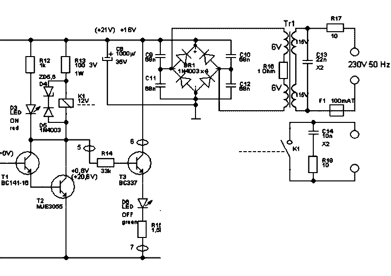
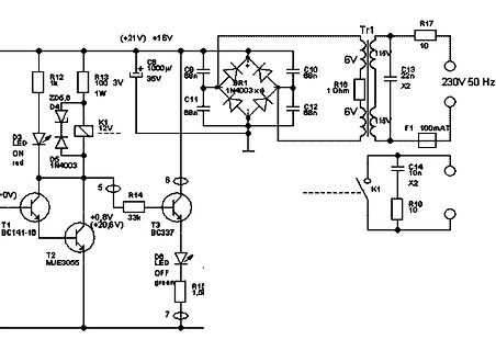
in dieser Schaltung. BC141-16 NPN/60V/1A/0,8W/Verstärkung 100 bis 250 BD249C NPN/100V/25A/Verstärkung 5 BD250C PNP/100V/25A/125W/Verstärkung 5 HFL60-S02 Fastrecovery Dioden 600V/70A
, habe mich heute nicht weiter mit beschäftigt, außer die Kabel (PWM-Leitung und Masseleitung) zum BC141 auszubauen und unter Belastung gemessen. War aber ok, morgen löte ich die R-Sense Leitungen ab um die kleine Platine mit dem BC141 rauszunehmen und zu testen. Vielleicht sorgen die Aluplatten für
Michael M. schrieb im Beitrag #7158412: > Ich habe jetzt mal je einen Darlington Transistor eingesetzt BC517 und > BC516. Die Verzerrungen sind sogar noch schlimmer geworden. Na ja, wenn man bei 2 Dioden bleibt. Insgesamt ist die Schaltung schon durch R3 versaut.
der alten Funkschau. Welche aktuellen (höherwertigen) Transistoren würde man heute anstatt der BC161 und BC141 hernehmen, die auch für 32Ohm KH geeignet wären?
Too many digits" -128,"Numeric data not allowed" -131,"Invalid suffix" -140,"Character data error" -141,"Invalid character data" -144,"Character data too long" -148,"Character data not allowed" -150,"String data error" -151,"Invalid string data" -154,"String data too long" -158,"String data not allowed
Surface-Mount Devices Figures S6-S15 — Typical Time-to-Trip Curves at 20°C femtoSMDCxxxF Figure S6 A BC DE G A = femtoSMDC005F 100 F B = femtoSMDC008F C = femtoSMDC010F 10 D = femtoSMDC012F E = femtoSMDC016F F = femtoSMDC020F 1 ( G = femtoSMDC035F i - t e 0.1 i T 0.01 E A C D G F 0.00.01 0.1 1 B 10 Fault
Keysight Gerät): https://www.keysight.com/de/de/assets/9018-03383/service-manuals/9018-03383.pdf (Seite 141). Filter nach fast allen Gain Blöcken. Das Phasenrauschen ist allerdings eine ganz andere Hausnummer.
Gerät): > https://www.keysight.com/de/de/assets/9018-03383/service-manuals/9018-03383.pdf > (Seite 141). Filter nach fast allen Gain Blöcken. > Das Phasenrauschen ist allerdings eine ganz andere Hausnummer. Schon heftig was da an filtern drinsteckt. Ich dachte immer das wäre nur bei einem spektrumanalysator

 Bild
Bild
 Bild
Bild
 Bild
Bild