FOR ALL-11 ***** BMI ***** Mfr. Device Type Device P/N ADP/CNV BIN. EXE. Ver. BMI EEPROM/FLASH/NVRAM BM29F020 NONE No Need WMEM1 V5.90 BMI EEPROM/FLASH/NVRAM BM29F040 NONE No Need WMEM1 V5.90 BMI EEPROM/FLASH/NVRAM BM29F400B ADP-29F800-PS No Need WA28F V6.15 BMI EEPROM/FLASH/NVRAM BM29F400B* ADP-49F800-PS/TSV2 No Need WA28F V6.15 BMI EEPROM/FLASH/NVRAM BM29F400T ADP-29F800-PS No Need WA28F V6.15 BMI EEPROM/FLASH/NVRAM BM29F400T* ADP-49F800-PS/TSV2 No Need WA28F V6.15 BMI EEPROM/FLASH/NVRAM BM29FS020 NONE No Need WMEM1 V5.90 BMI EEPROM/FLASH/NVRAM BM29FS040
P 2 . 0 - P 2 7 sv) potdPORTO p ePO2T| Vs DRIVERS DRIVERS t =o > 128B {if t (= av PORT 9 Lisciay = ft LACH ak8 = POINTER ADDRESS _ i! TMP1 EITR P c L a E a | ceon|scw |to| cN | onwnrn p> 1 eurmofsI N T E R A U P T PSEN z | r w IERCLKSORT OUTRRAM a s | , me, [oS : t i RST n e ee ee F= a e eka] l e e P
982 ist ein Nachbau des JBC-Systems (Spanien), und kann --je nach angeschlossenem Handstück-- mit C245 oder C210 verwendet werden. C245 sind größer, C210 sind schon sehr filigran. Es gibt auch eine 982-III, die ist primär für die Verwendung mit C210 und den nochmal deutlich kleineren C115 vorgesehen
wenig sein könnte. 200W, 180W, 40W? Die C210-Lötspitzen leisten bei Betriebsspannung 40W, die C245-Lötspitzen leisten 110W. Die Yihua 982 hat bei Betrieb mit C245-Lötspitzen dementsprechend auch eine Leistungsaufnahme von gut 100W: https://www.mikrocontroller.net/topic/560647#7527914. Was da mit
the calculation (see Figure 2–21). Thus, generator signal level can be specified in dBm, and the correct power will be delivered to the load. NOTE. This is calculated dBm, so if the external load is not as stated in the Output dBm box, the output value stated in dBm will not be correct.
(i.e. the constant component) base resistaBme. The base resistance is linear (bias independent), iBmR equals (or is greater thaB) R . R B R Bm R Bm + forRB = ∞ RBB ′= QB (11.64) R Bm + 3· (RB− R Bm ) ·tanz − z forRB = ∞ z · tan z 144 IB 1 + 2 · − 1 with z = π IRB (11.65) 24 IB 2 · π IRB The
used in an FT245 Style Synchronous FIFO Interface...........20 3.2.4.3 FT2232H-56Q pins used in an FT245 Style Asynchronous FIFO Interface .........21 3.2.4.4 FT2232H-56Q pins used in a Synchronous or Asynchronous
used in an FT245 Style Synchronous FIFO Interface...........20 3.2.4.3 FT2232H-56Q pins used in an FT245 Style Asynchronous FIFO Interface .........21 3.2.4.4 FT2232H-56Q pins used in a Synchronous or Asynchronous
Teil ist mit einem FPGA realisiert. Ansonsten gibt es noch 2 74HC573, einen 6-fach Inverter und einen FT245BM für USB Gedöns. Um dem Teil erst mal überhaupt etwas beizubringen damit es mit einem redet gibt es noch einen Pseudo-Z80 mit einem STM der an Stelle des Z80 eingesteckt wird, womit der Flashspeicher
appropriate for most applications. C H OST NTERFACE p following relationship: bus mode is determined by BM[1:0] and {DB15, DB13} by the BM[1:0] {DB15, DB13} Mode 11 cData 6800/16-bit 10 Data 8080/16-bit BM0 I 1 r BM1 1 01t 0x 6800/8-bit l0 0x 8080/8-bit 00 10 4-wire SPI w/ 8-bit token (S8: conventional) U
nicht brauchte. Ich habs dann gefunden: Was ist libftdi1-2 Diese Bibliothek könnte mit FTDIs FT232BM, FT245BM, FT2232C, FT2232D, FT245R kommunizieren. USB-Chips vom Typ FT232H und FT230X aus dem Userspace. Es verwendet libusb 1.0 mit den Chips kommunizieren. Zu den Funktionalitäten gehört die
Circuits for Automatic Band Scanning, Part 1: A Simple Band Scanner E G Hoffschildt, DL9FX 1970/4 245 - 248 Miscellaneous Two Circuits for Automatic Band Scanning, Part 1 : A Simple Band Scanner E G Hoffschildt, DL9FX 1970/4 245 - 248 Audio Frequency Speech Processing - Practical Circuit of an Efficient
be- denADC)liefertderFT232RLgleichmit, stimmenkann. Aus allen drei Beschleuni- so dass ein zusätzlicher Spannungsregler gungswerten lassen sich die Neigungs- für 3,3 V entfällt. winkel in X- und Y-Richtung sauber be- NunkommtetwasMathematik
eineEndstufemiteinerVerstärkungvon10dB D Ampere (A) angeschlossen.WiegroßistderAusgangspegel derEndstufe? A 40dBm AA103 Welche Einheit wird üblicherweise für die B 30dBm Energieverwendet? C 20dBm A Joule (J) bzw.Wattstunden (Wh) D 10dBm B Volt (V) bzw.Watt proAmpere (W/A) C Watt (W) bzw.Joule pro Stunde (J/h) AA110
ANALYZER INSTRUCTION MANUAL 10.5 YTO-CONT Adjustment (YTO-CONT/IF Board) - - - - - - - (BLR-O 15116 oft v9Ft 1 J 7 k 1 0 9 S e t th e S G o f O M tu n e A a s fo lio w s: FREQUENCY: 800 MHz AMPLITUDE: +0 dBm @ R 4 1 3 1 a s fo lio w s : CENTER FREQ. : 0 MHz F R E Q . S P A N : 20 M H z CF CAL @ : A d ju st
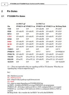
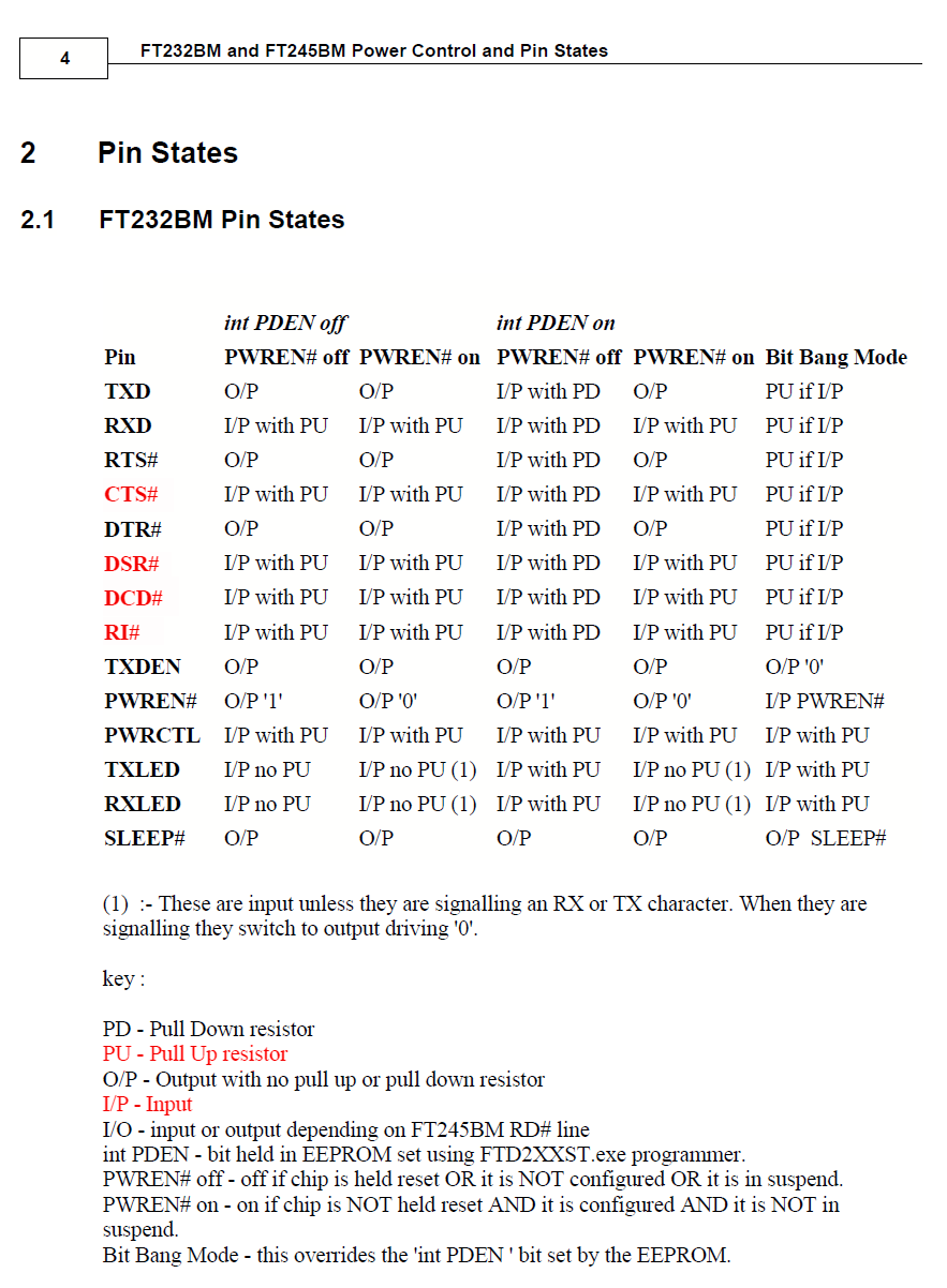
4 FT232BM and FT245BM Power Control and Pin States
2 Pin States
2.1 FT232BM Pin States
Pin int PDEN off int PDEN on
PWREN# off PWREN# on PWREN# off PWREN# on Bit Bang Mode
TXD O/P O/P I/P with PD O/P PU if
read all voltages or attenuation values directly in Fig. 31; Principle of the logarithmi c CIrcuit dBm or dB on the linear scale of the meter. It is only necessary for the meter to be marked in the opposite direction from - 10 to0 lor the with the most important components, and the dBm-indication. associated
read all voltages or attenuation values directly in Fig. 31; Principle of the logarithmi c CIrcuit dBm or dB on the linear scale of the meter. It is only necessary for the meter to be marked in the opposite direction from - 10 to0 lor the with the most important components, and the dBm-indication. associated
-61 I > 51 1 T2: 35t #304fc l i FT-50B-43 -=r Fig 5.27—Test circuit used to evaluate the performance of the NE602. Most measurements used a 14-MHz RF, 19-MHz 0-dBm LO, and an IF of 5 MHz. The output 1 dB bandwidth extended from 0.5 to
aktiver Tiefpassfilter Aristoteles Tsiamitros DD 5 FT 2008/2 81 – 94 Filter Kaskadensynthese von aktiven Bandpassfiltern Aristoteles Tsiamitros DD 5 FT 2008/3 147 – 163 Filter Kaskadensynthese von aktiven Bandpassfiltern Aristoteles Tsiamitros DD 5 FT 2008
Aristoteles Entwurf aktiver Tiefpassfilter Tsiamitros DD 5 FT 2008/2 81 – 94 Filter Aristoteles Kaskadensynthese von aktiven Bandpassfiltern Tsiamitros DD 5 FT 2008/3 147 – 163 Filter Kaskadensynthese von aktiven Bandpassfiltern Aristoteles DD 5 FT 2008/3 147…163
Eberhard L. Smolka 2007/4 243 - 246 DB 7 UP Dämpfungsglieder AristotelesTsiamitros, 2008/1 35 – 48 DD 5 FT Bakencontroller mit ATmega32 Wolfgang Schneider, 2008/1 49 - 60 und Bascom DJ 8 ES Entwurf aktiverTiefpassfilter AristotelesTsiamitros, 2008/2 81 – 94 DD 5 FT Aktuelle digitale Funkstandards Michael
genauer angesehen und 2 Parameter auf die Werte für LF357 geändert habe. Ändert sich nicht viel, da fT bereits mit 20 MHz angegeben war statt 25 MHz. Was fehlt, sind die Pins für den Offsetabgleich.
empfangsmäßig mit Störungen zu rechnen ist.Der Grundpegel ist auf 17.2 kHz auf linker Seite um ca 12 dBm höher als für 10 kHz rechts. Das es bei 9.5 kHz noch ein nicht AFU-Nutzsignal gibt, hat mich auch gewundert.
0.1UF 0.1UF 0.1UF . A G G G G G G G G 2100 Logic Drive A 2 6.3V 2 25V 2 25V 2 25V 2 2 1 1 3 X N N FT4232HL_LQFP64 0 1 5 1 5 5 5 7 1 San Jose, CA 95124 USB_PWRD_VCCIO G G 1 1 1 2 3 4 5 FTDI_PWREN_B Q19 C103 1 2 4 1 C104 DMN26D0UFB4-7 27PF 27PF 1 Title: ML Starter Kit Carrier Card 50V 2 2 50V 1 C99 1
Du könntest auch ein UM245R von FTDI nehmen und als Signal das WR or RD anzapfen. https://www.mouser.de/ProductDetail/FTDI/UM245R?qs=Xb8IjHhkxj4TWAlYgWlsig%3D%3D&mgh=1&vip=1&gclid=EAIaIQobChMIyoyTkcS0-gIVxvV3Ch2T1gh0EAQYAiABEgK18fD_BwE
generieren > und das aus Windows über python. Wieviele Schritte? Von 1T bis 10T gibts per TxD eines FT232 bei passender Baudrate.
used in an FT245 Style Synchronous FIFO Interface...........20 3.2.4.3 FT2232H-56Q pins used in an FT245 Style Asynchronous FIFO Interface .........21 3.2.4.4 FT2232H-56Q pins used in a Synchronous or Asynchronous
www.mattwei.de ..ist Geschichte. Das Ding ist nichts weiter als eine kleine Platine mit Atmega8 und FT245BM für universelle Anwendung, aber eine der Hauptapplikationen war damals ein STK500 kompatibler ISP Programmer und als solchen habe ich den auch regelmäßig benutzt. Nun ist das Ding mal wieder kaputt
habe ich da das MOSI Pin beschädigt, kein H Signal mehr. Nun gut, sowohl der Amtega8 als auch der FT245BM sind nicht die ersten auf diesem Ding, die habe ich beide schon mal gewechselt wegen Defekten, kein Ding, sowohl Schaltung als auch Software liegen nach wie vor auf meinem Rechner. Nun habe ich
dem RF-Kram via Disassembler ansehen. Zum Auslesen gibt es verschiedene Möglichkeiten: FTDI FT232R: https://github.com/jdelfes/nrf24le1_flasher [c]nrf24le1_flasher --read-flash readout.bin[/c] RaspberryPi: https://github.com/derekstavis/nrf24le1-libbcm2835 [c]nrf24le1 show nrf24le1 read
[c]CMDs: 0x1: 97 0x2: 193 0x3: 145 0x81: 0 0x82: 0 0x83: 0 0x84: 65 other: 0 Send Cnt: 245 MQTT: connected[/c] Kann ich das irgendwie anders prüfen ?
= V 2.1 V; other CC I CC inputs at CC or GND; V CC = 4.5 V to 5.5 V pin E - - 294 A pin Sn - - 245 A 9 9 && && ( ( 9,+ 9 ,/ <Q = = <Q 9 6: 6: 6: RV 9LV *1' 9RV 9LV *1' ▯▯▯DDJ▯▯▯ ▯▯▯DDJ▯▯▯ Vis V CCand Vos = GND V isV CCand Vos = open Vis GND and V os = VCC V is GND and V os = open Fig 10. Test circuit
bugs detector diode TSS Glass SMD Ceramic or special (tangential sensitivity) case case case -59 dBm @ 2 GHz HSMS 2850 - 2851 SMS 7630 -55 dBm @ 10 GHz these are the much sensitive diodes at usable up to 18 GHz ZERO BIAS -53 dBm @ 2 GHz ND 4991 - 1SS276 DDC2353 -55 dBm @ 6 GHz LOW BARRIER up to 20 GHz from -54 dBm to -52 dBm all BAT 15… types are LOW BARRIER up to 24 GHz depending on type high sensitivity vatious types available -56 dBm @ 2 GHz with bias HP 5082-2824 HSMS.282…series low barrier, up to millimeter
gesundheitsschädlicher. Aber wir haben ja jetzt alle Masken ;-) Anbei noch die Messung des kleinen FT-37-61 Kerns mit 75 Windungen 2x0.2CuL parallel, 3x wäre wohl nicht mehr drauf gegangen. Sie hat ca. 245µH und 9.6pF mit einer Eigenresonanz bei 3.24 MHz. Q ist zwischen 0.27 und 1.27 MHz oberhalb von
Point_IP3 Etwas ausführlicher: http://edi.bplaced.net/images/grundlagen/Empfaeengermessungen/FT_1949_heft_16_Kunstantenne.pdf
Schalter S2 oder S3 rückinte griert wird, gilt folgender Ansatz: t,+t, 0 J urr dt =-Cl J dUaN!· (3) ft R UINI Hier liefert die Lösung der Integrale: (4) BildI3 VerlaufderAusgangsspannung df IntegratoNI Stellt man die Beziehung (2) nach UaNJ um nach BildI.Iwährend derAID-Wandlung einer und setzt den so
verwendet (s. Bild) mit der 3dB-Methode. Die Leistung vom Funktionsgenerator am Eingang beträgt +10dBm, so dass am Quarz selbst etwa -5dBm ankommen. Messwert-Aufnahme macht ein empfindliches HF-Voltmeter (HP400F). Die Serienresonanz usw. sind erstaunlich gut (und reproduzierbar) aufzunehmen und ich
Bernhard S. schrieb im Beitrag #6361010: > Aus den +10dBm vom Generator kommen am Ausgang deiner Messapparatur > höchstens -20dBm an, das sind 22mV. Nochmal 70 dB abgezogen sind das > etwa 7µV. Kannst du das mit dem Voltmeter noch detektieren? Hallo Bernhard

 Bild
Bild