🤣🤣🤣👌🏼

Klaus.
Boleslaw J. schrieb:
> Such a graphic form of the result has no substantive justification. It
> adds nothing to the result of the remote control test. This is an
> unnecessary, but attractive addition to encourage a potential customer
> to buy something that other Chinese products with a similar purpose do
> not have. The same applies to the color barcode when measuring
> resistance. Since I already know the resistance value, I do not need a
> color code.
> I took up this topic only because I wanted to occupy my free time with
> something interesting.

I find it useful when I am new to a protocol to get a quick glimpse of
how the data is encoded.

I find it useful, and I would appreciate if you share the code so that
the firmware developers can pick up.

That is "hacky thinking" also: Do not assume the usefulness of a
feature, because someone else might find a use you never could think of.

Regards!
Holger B. schrieb:
> I find it useful, and I would appreciate if you share the code so that
> the firmware developers can pick up.

That's what I was going to do.
But first I need to finish implementing these graphics for all IR
protocols.

Regards,
Boleslaw
Angehängte Dateien:
-

20230520_081641.jpg
230 KB
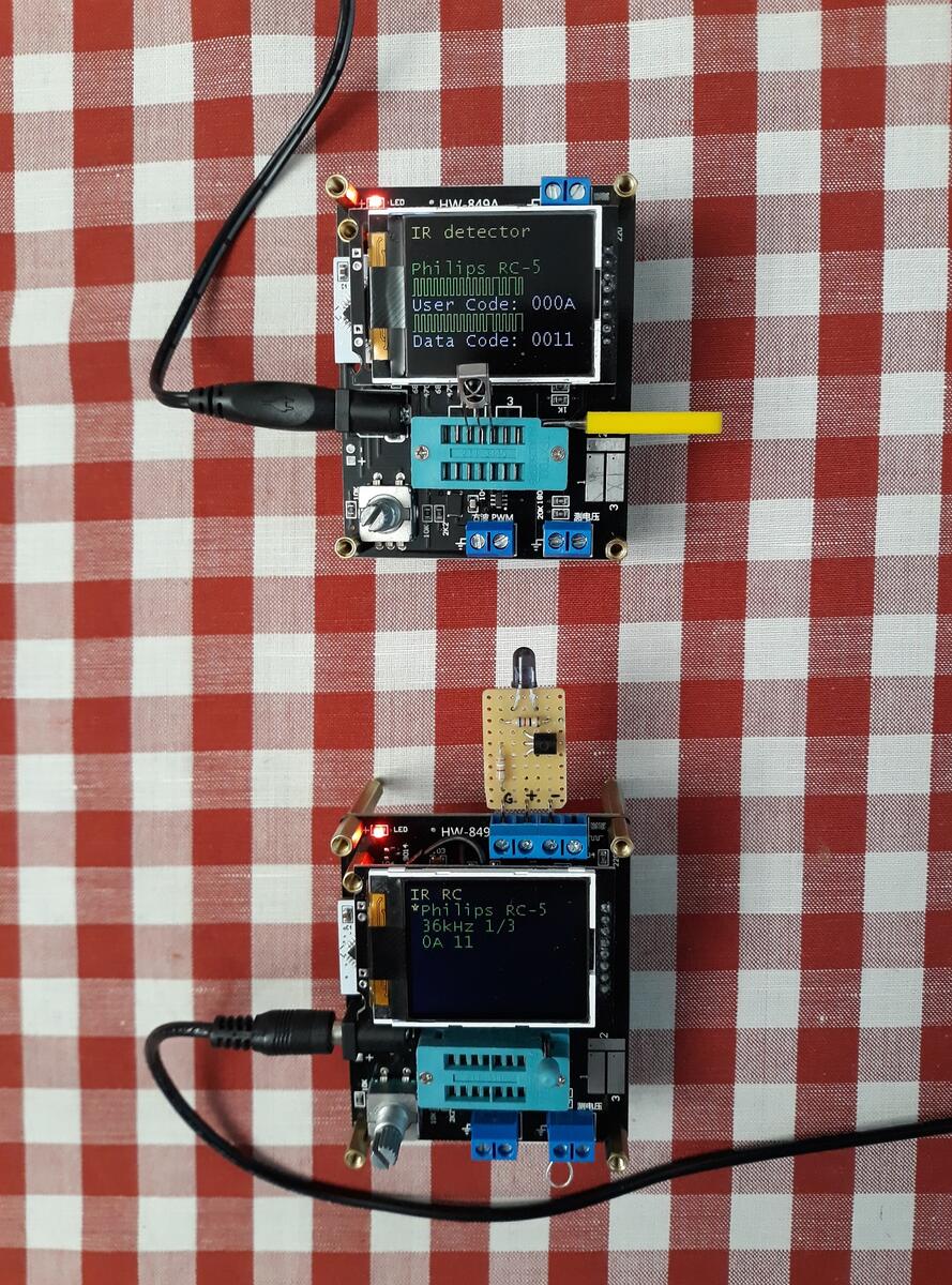
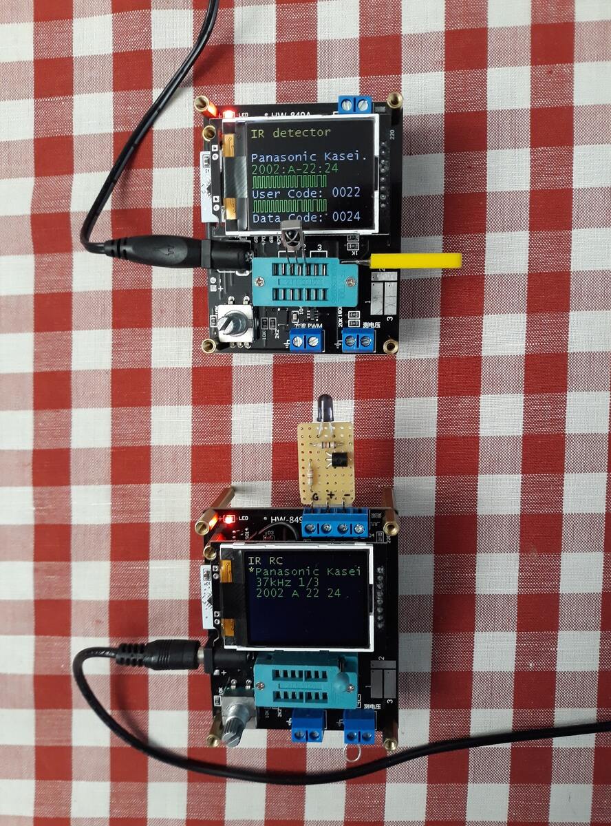
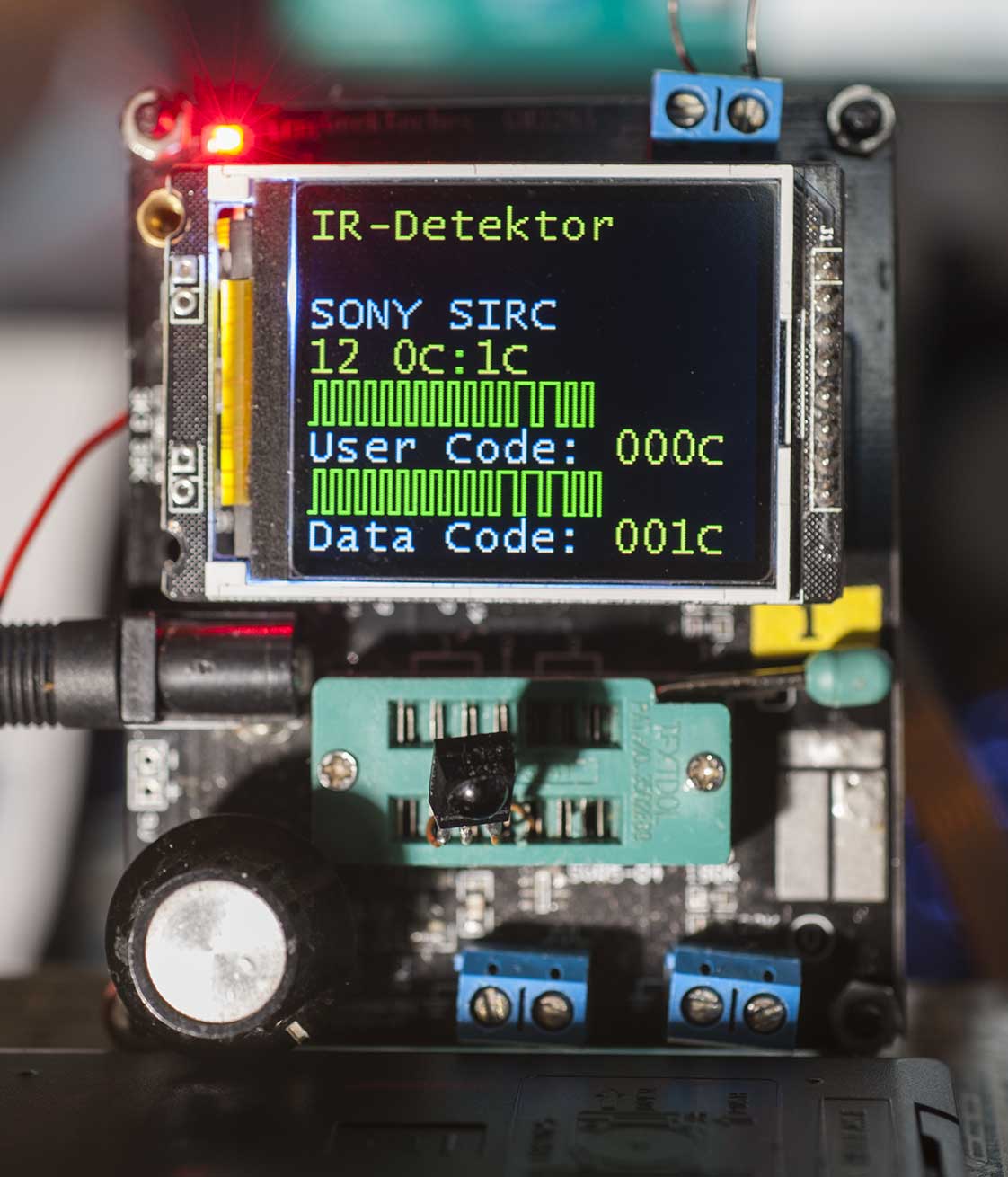
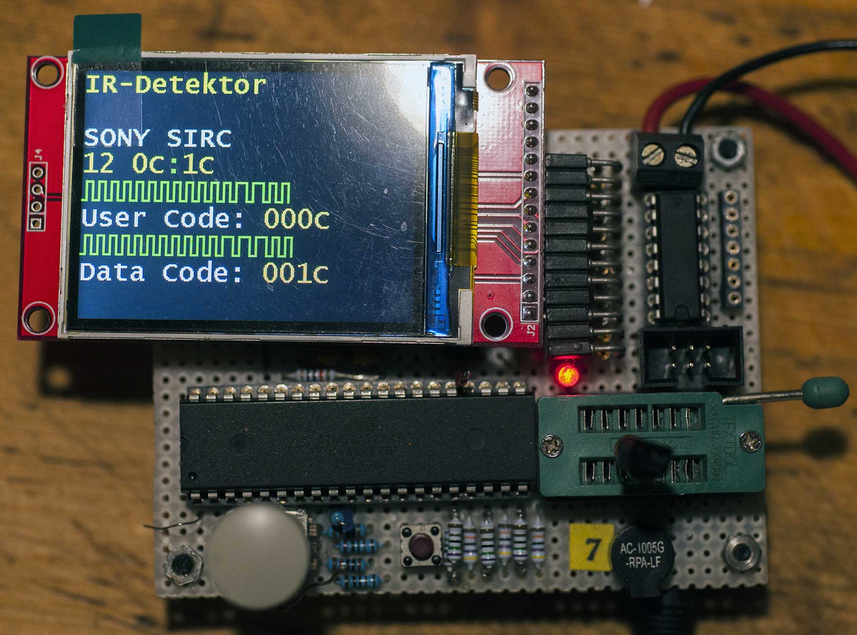
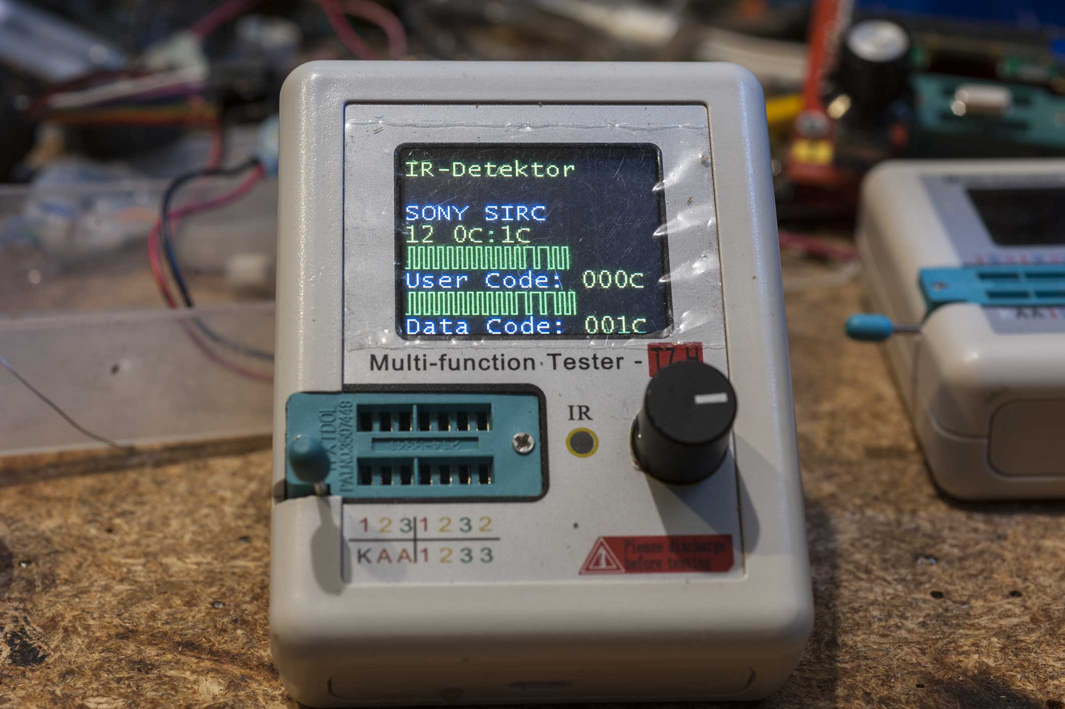
The original, complete information about the data sent from the remote
control, which Mr. Reschke fit in one line, will be supplemented with
graphics simulating the image from the oscillograph.
I finished implementing graphics for the IR detector. I ran the tests on
several remote controls to which I have access. The remaining tests will
be performed after receiving the m328-644 adapters from China. They are
already after customs clearance.
For testing, I will use a second AY-AT tester on ATmega644. I already
have an additional tester and microcontroller. For testing, I will use
the IR RC function of the second tester.

I will give the modified files to the author of the program, Mr.
Reschke. He will decide whether to include the changes in the next
version of the program. I have no right to publish modifications without
the program author's permission.
Boleslaw J. schrieb:
> I have no right to publish modifications without the program author's
permission.

Why this?

As I see, the license is EUPL 1.1 (see file "EUPL-v1.1.pdf" in the
source code directory), and it allows

> *modify the Original Work, and make Derivative Works based upon the Work,*

under some conditions (which mainly are about notices in derived work,
license of derived work, ...)
Holger B. schrieb:
> Why this?
>
> As I see, the license is EUPL 1.1 (see file "EUPL-v1.1.pdf" in the
> source code directory), and it allows
>
>> *modify the Original Work, and make Derivative Works based upon the Work,*
>
> under some conditions (which mainly are about notices in derived work,
> license of derived work, ...)

You are right, but Mr. Markus Reschke has been conducting this topic for
many years, he does it, as I noticed, very well and in addition
selflessly, so he has the moral right to decide what will be included in
the program, which he signs with his own name. That is my opinion.
Otherwise, there will be a mess in the software that will be difficult
to control.
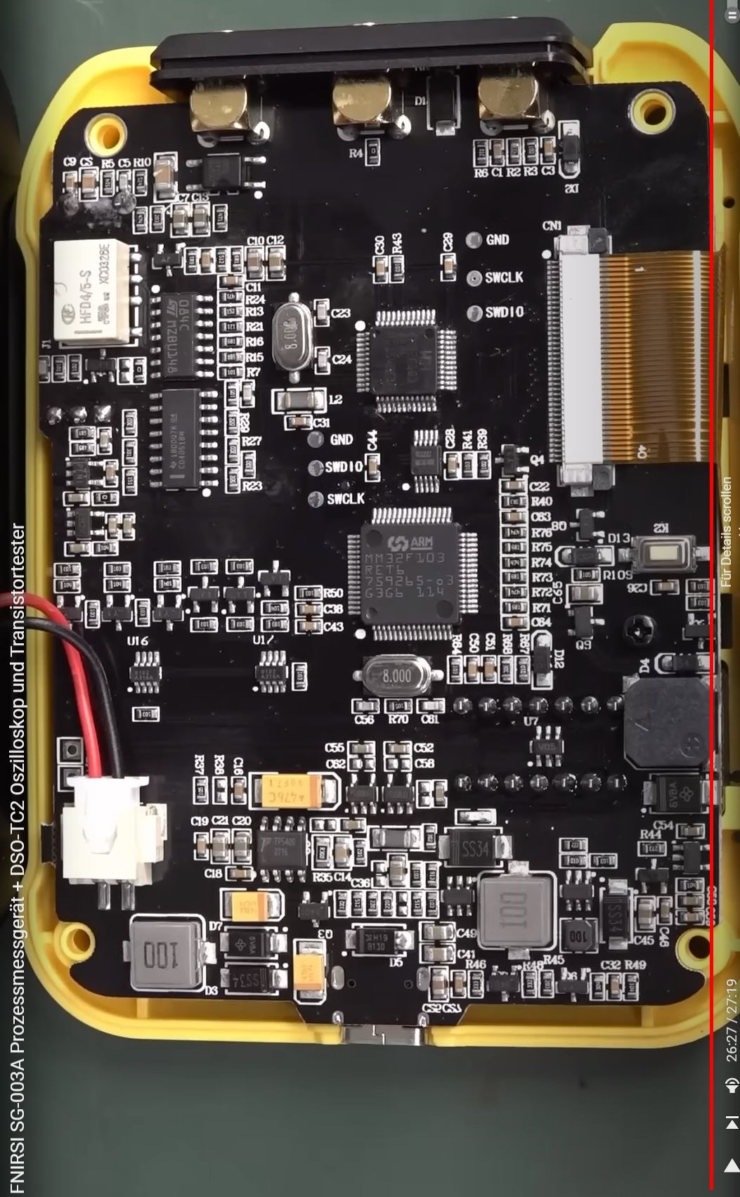
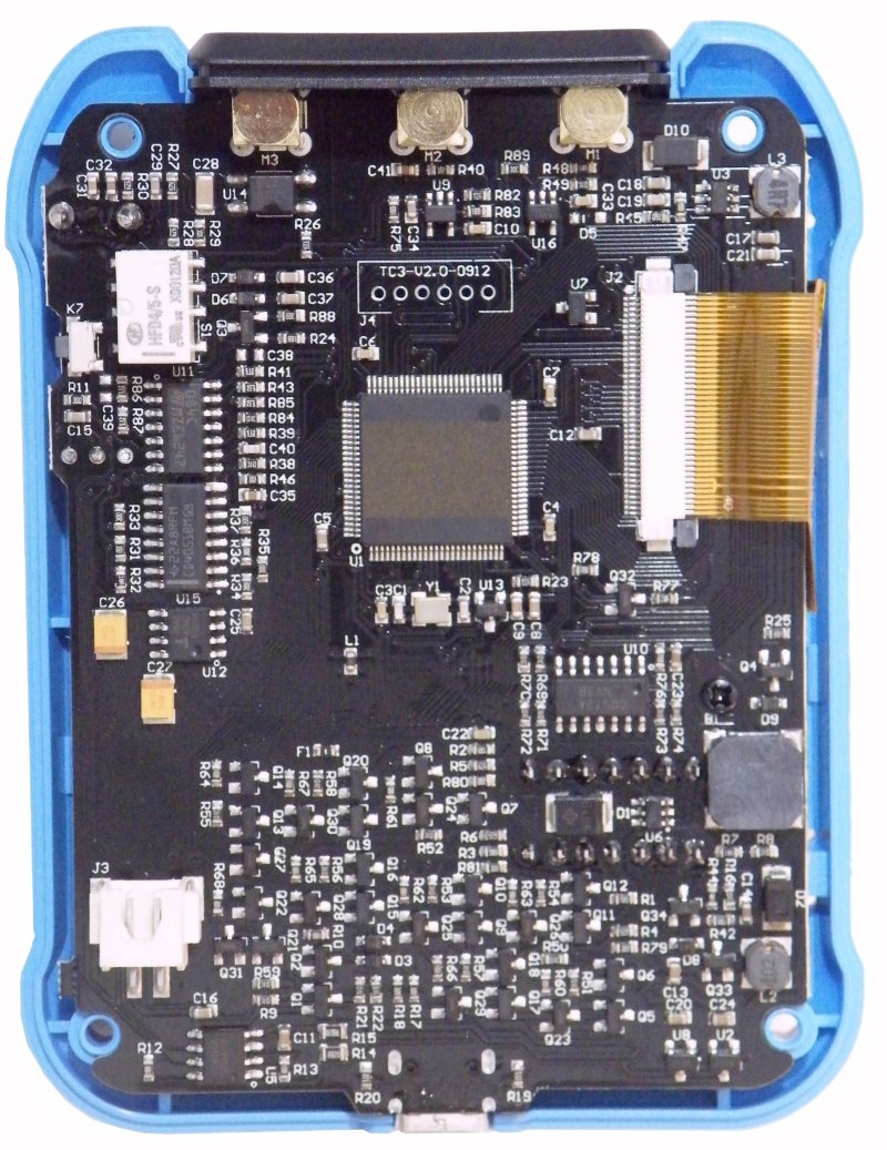
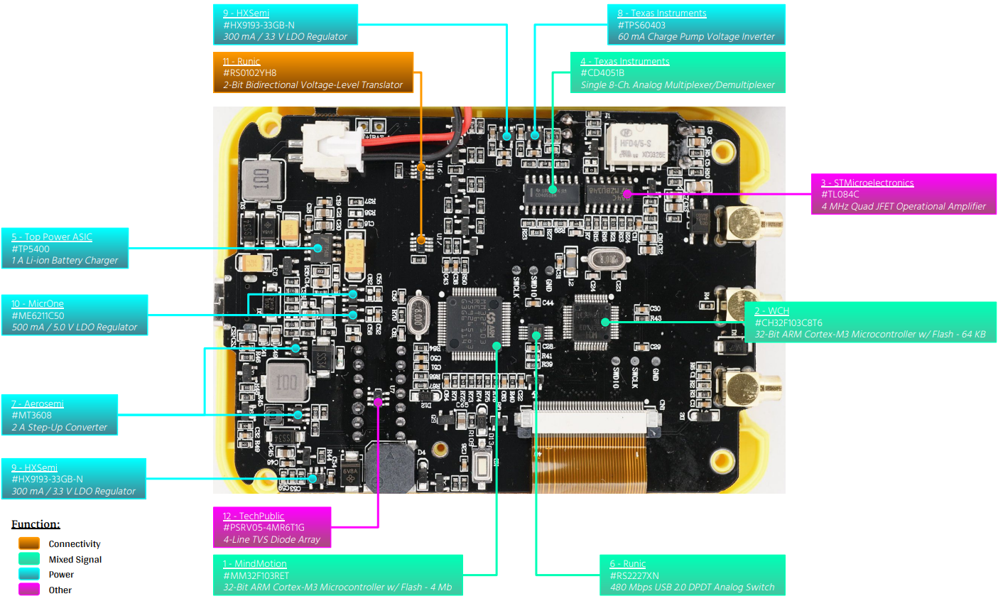
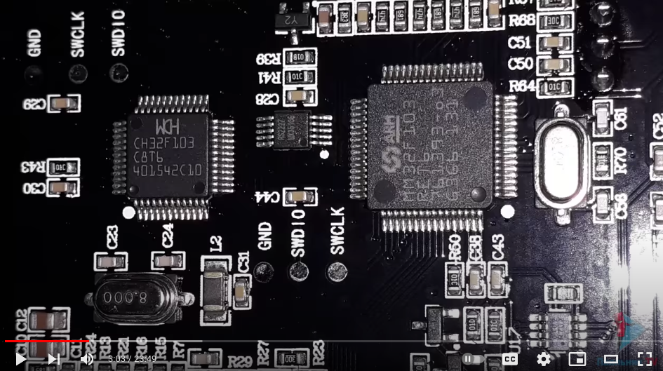
Carsten W. schrieb im Beitrag #7077914
> Aber sieht interessant aus. Würde ich gerne mal aufmachen und reinschauen.
besser spät als garnicht!
Die eine Version verwendet zwei ARM Controller, bei der anderen ist nur
ein Controller verbaut wobei die Type unbekannt ist (nicht lesbar)!
https://de.banggood.com/FNIRSI-DSO-TC2-Handheld-Digital-Oscilloscope-LCR-Meter-Graphic-Display-Transistor-Tester-2_4-inch-TFT-Color-Screen-LED-Backlight-for-Auto-Repair-Appliance-Repair-p-1955385.html
https://de.banggood.com/FNIRSI-DSO-TC3-Digital-Oscilloscope-Transistor-Tester-Function-Signal-Generator-3-in-1-Multifunction-Electronic-Component-Tester-p-1982523.html
R. H. schrieb:
> besser spät als garnicht!
:-)

Wäre mal interessant, die Mess-Schaltung des 122er zu sehen. Der µC wird
ja 3.3V als I/O-Spannung haben und eine sich sehr vom Atmel
unterscheidende interne Portstruktur.

Aber bei dem 2523 sind dem Designer wohl die Pferde durchgegangen. Wozu
braucht man 30 Transistoren in der Mess-Schaltung?
Beitrag #7420347 wurde von einem Moderator gelöscht.
Angehängte Dateien:
Da der Vorgänger TC2 zwei ARM µC STM32 verwendet hat (einen für das DSO
und den kleineren für den T-Tester) gehe ich mal davon aus das man das
jetzt alles in einen großen gepackt hat z.B.  STM32F407VET6. Vor 2
jahren hat ja schon mal jemand die T-Tester SW auf einen
STM32F103/GD32F103 oder GD32F303 portiert, vllt. hilft das ja weiter
(für Leute die sich damit auskennen) ;-)
https://github.com/mean00/stm32ComponentTester
Angehängte Dateien:
-

20230524_095041a.jpg
230 KB -

20230523_154232.jpg
240 KB
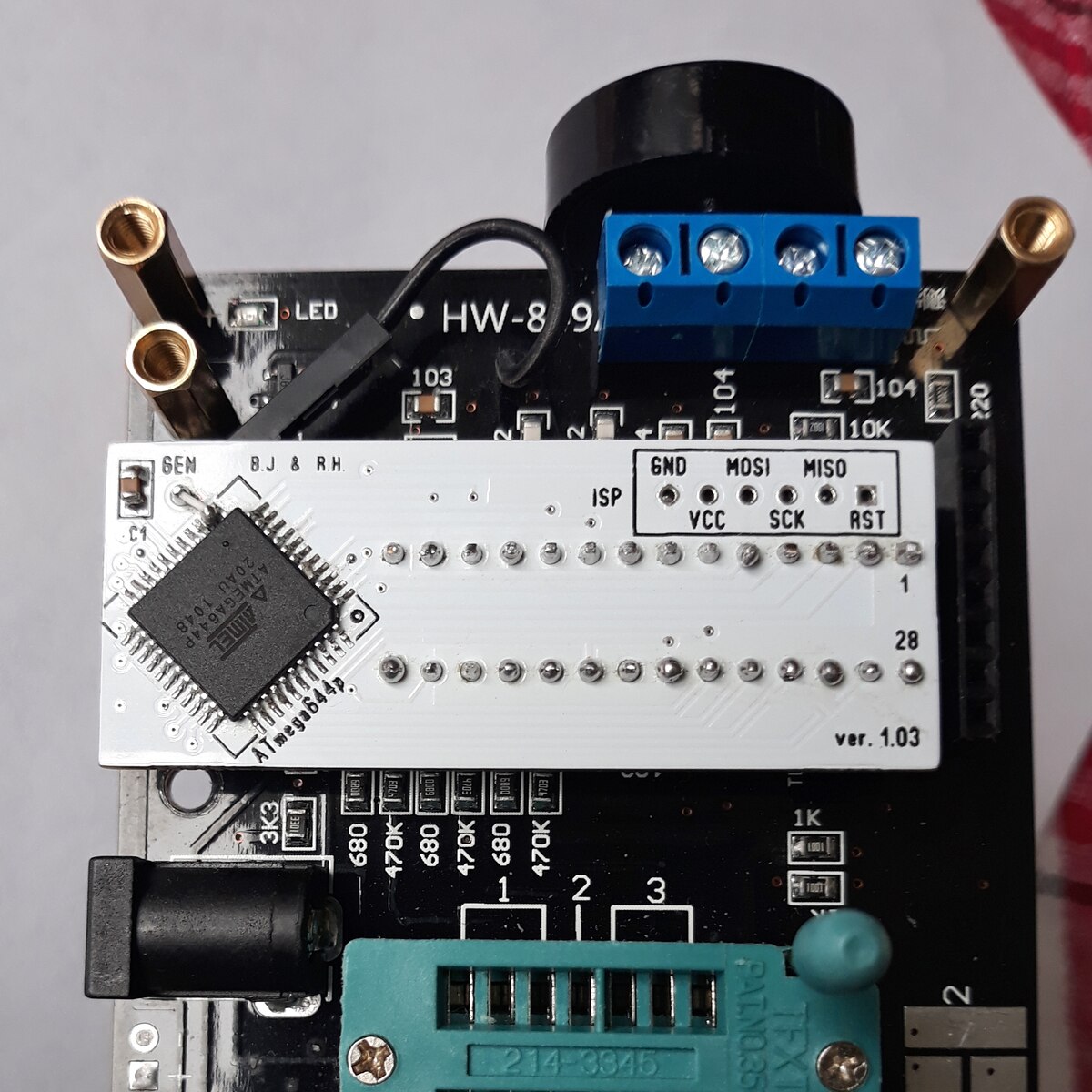
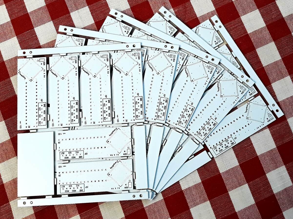
The shipment from China has arrived.
Hello Boleslaw 43,

Do you also sell any of these boards, if so, I would like to buy two?

Greeting Horst
Hello Boleslaw_43,
if you sell some of this boards, I also would like buy two pieces of
them.
Best regards
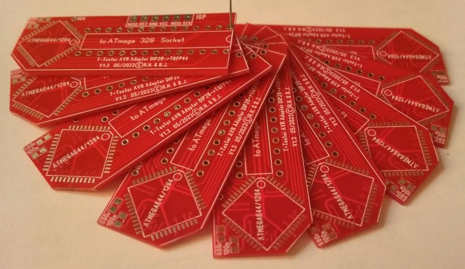
Thank you for your interest.
Since this is my first PCB project, I treat it as a training material.
Therefore, to Forum users residing in the EU, as part of the promotion,
I send the adapter for free.
Please send postal addresses for shipping to my PM.
Angehängte Dateien:
-

20230527_191544_50.jpg
240 KB -

20230527_193558_50.jpg
240 KB
Tests and fixes in progress.
Angehängte Dateien:
-

Motorola_Code.jpg
230 KB -

20230531_071125.jpg
240 KB
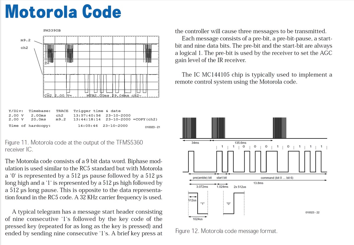
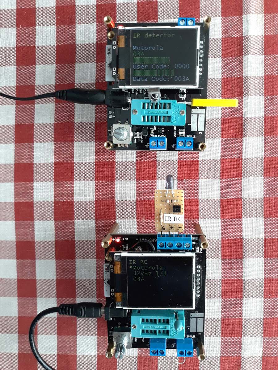
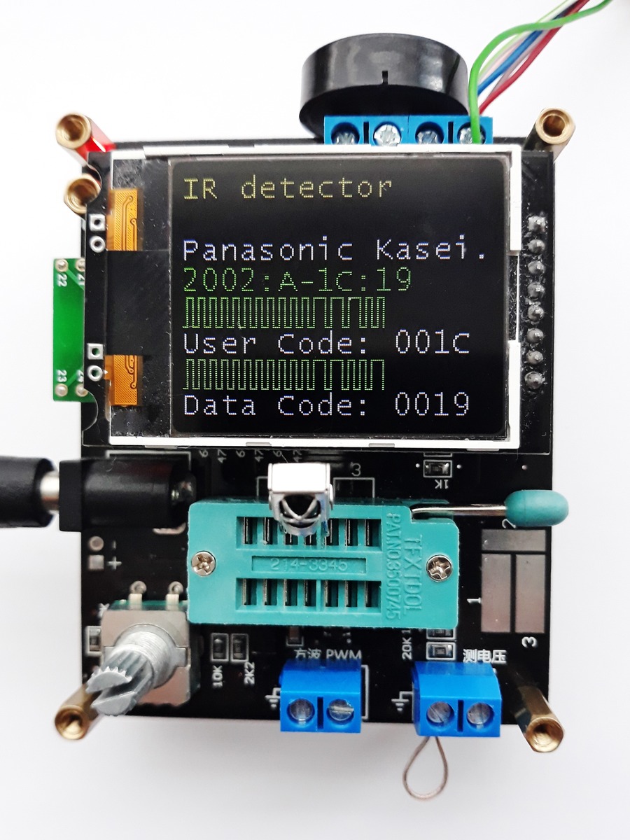
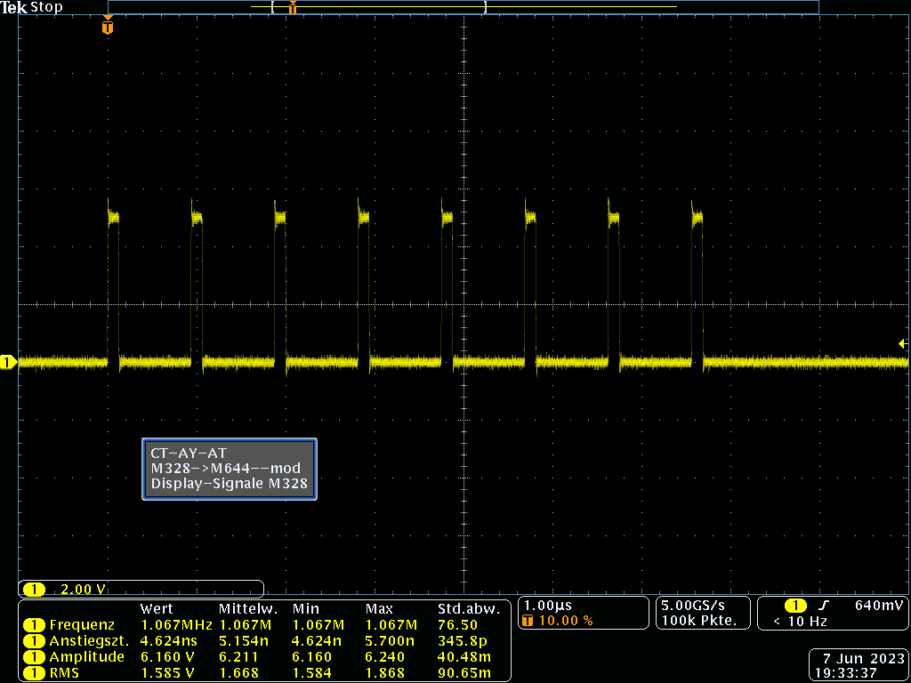
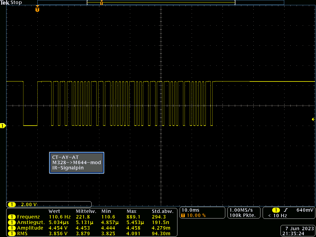
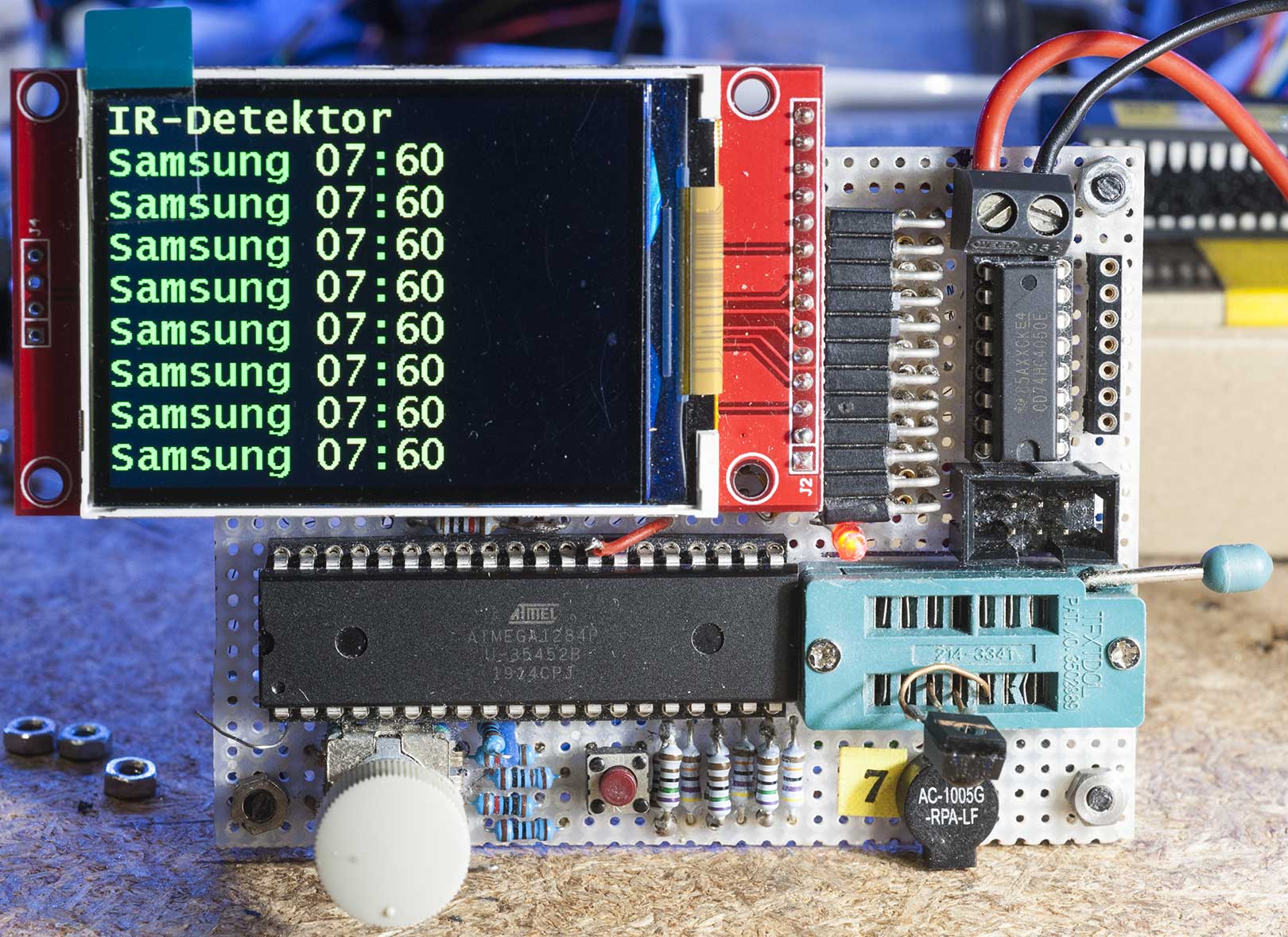
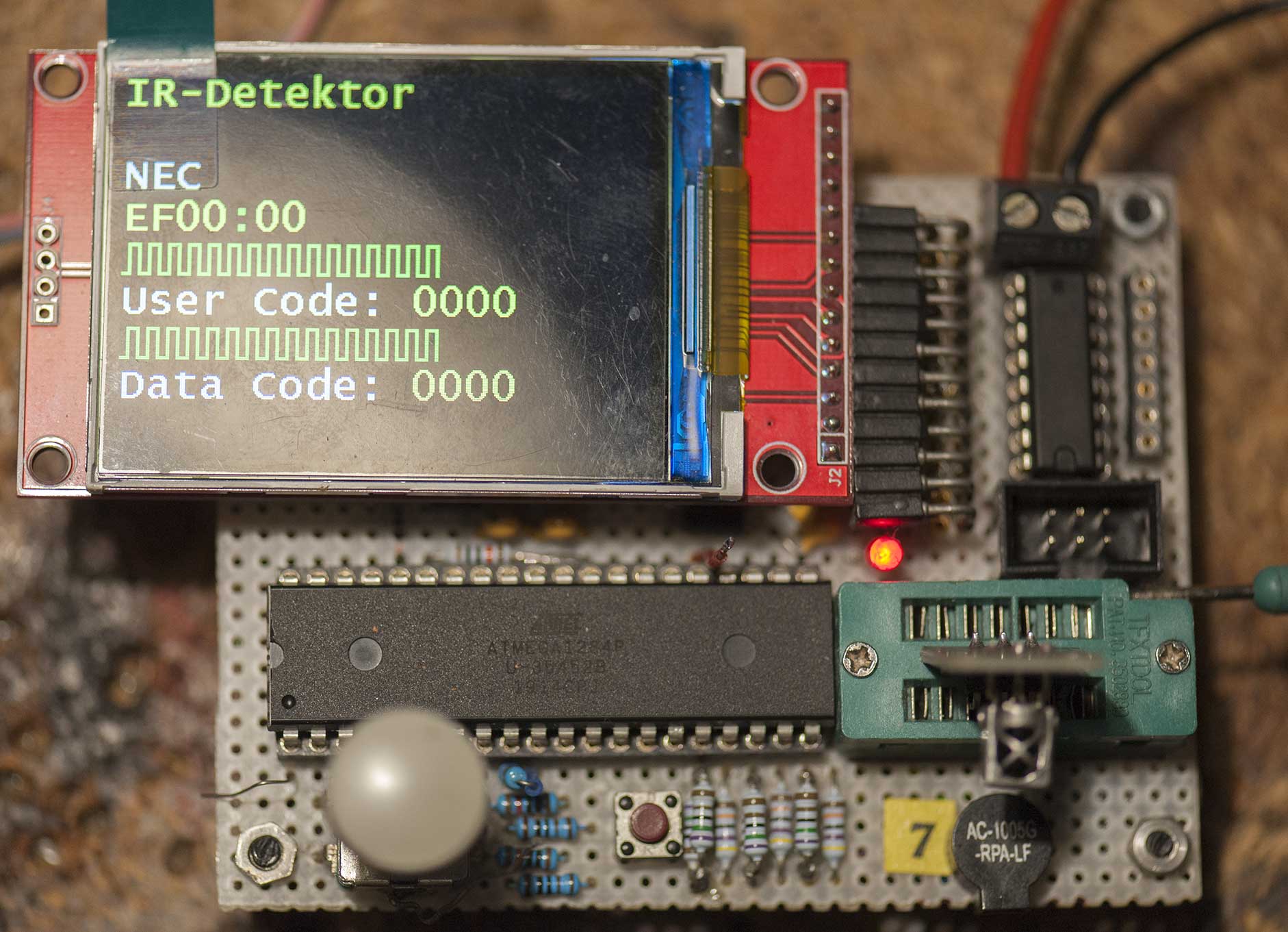
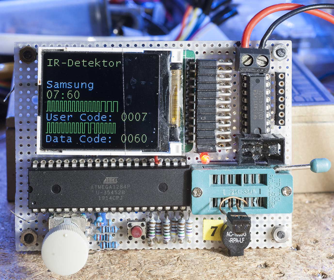
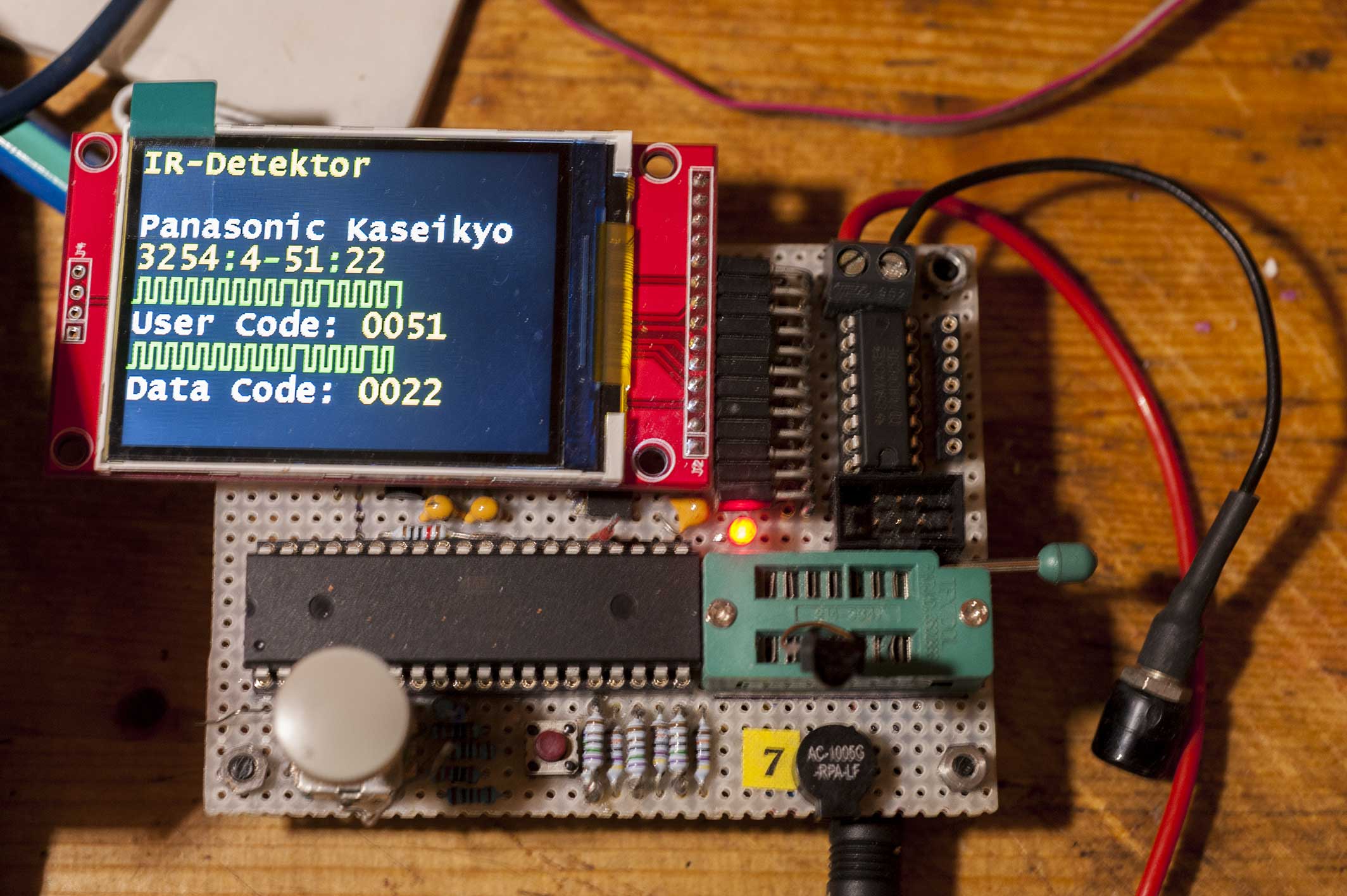
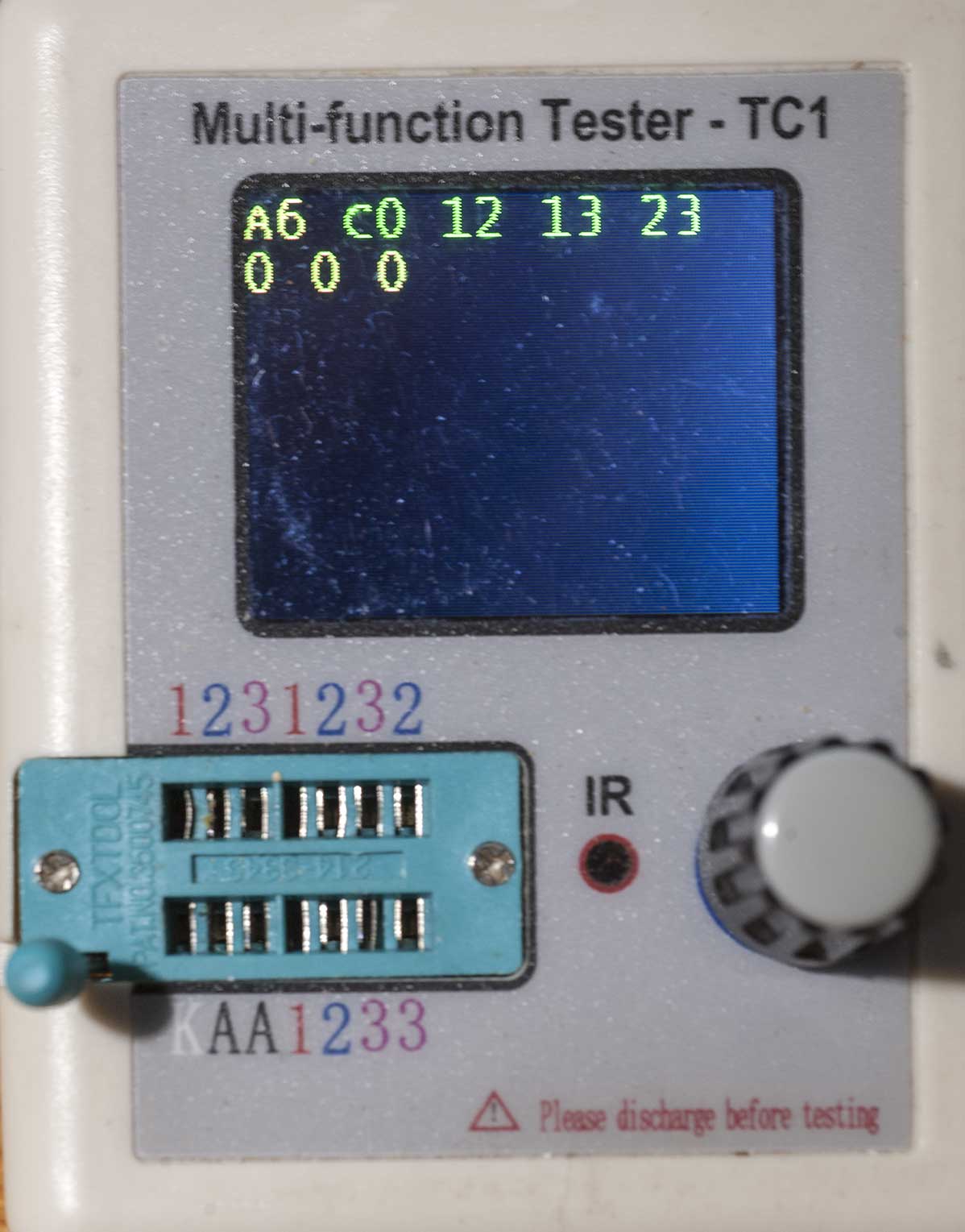
I have finished the implementation of the graphical form (a la
oscillogram) of the data read from the remote control for the "IR
detector" function, for the protocols entered into the Component Tester.
It took me a while because I ran into a problem reading data according
to the Motorola protocol that I could not understand. On my 8 megahertz
AY-AT tester, the IR receiver was unable to read the data transmitted by
the second Component Tester, set in the "IR RC" function to the
"Motorola" protocol.

I understood the reason by analyzing the IR protocol provided by
Motorola. After a short press of a key on the remote control, its
transmitter sends three packets of bits at strictly defined intervals.
The first package contains 9 ones - this is a starter package. The
second package contains the right command, and the third package, also
containing 9 ones - is a package ending the data transmission from the
remote control. By holding down the remote control key for a longer
time, the remote control repeats the command packet until the key is
released, which results in sending the end package (9 ones).  Well, the
time that elapses between sending the first packet of bits and sending
the second packet of bits is too short for the receiver to notice it,
busy at that time interpreting the received first packet. This second
packet, containing the command, was simply lost.

This critical time can of course be extended in the "IR RC" function,
which I did, but the real Motorola remote control does not have such a
possibility - it sticks to the established protocol.

The elegant, multi-packet handling of received packets did not work in
this case. The solution to the problem may be to receive three or at
least two packets in one cycle and remember them in RAM for later
analysis. This is a proposal to be included in the To-Do list for the
author of the program.
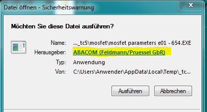
Transistortester AVR Windows-Software !?
Hallo
bin beim stöbern im Netz zufällig über diese Software gestolpert:
https://disk.yandex.ru/d/MHdHzZehqqzUi
scheint aus einer russ. Quelle zu stammen und ist wahrscheinlich mit
Profilab von ABACOM erstellt!? kennt die zufällig jemand und weis über
die Funktion, Anschluss an den T-Tester (seriell), Änderung an der
Firmware usw. bescheid?
Gruß
Das sieht ganz nach der Software vom "Messtechniker" aus.
Musst mal hier im Faden suchen.
Ist aber "einseitig", also nur RX vom Tester.
Testerausgang ist Pin26 vom 328.

Gruss Asko
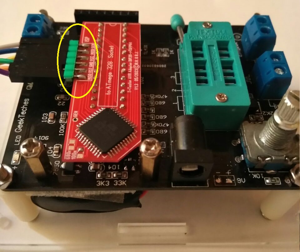
For people to whom I sent adapters m328_m644 for AY-AT, I share the
modified firmware.
The firmware has been supplemented with a graphical result of remote
control tests, SPI hardware support for the ST7735 display and generator
output from the OC1B port of the microcontroller.
The zip archive also contains the current adapter connection table for
version 1.03 (white).
Boleslaw J. schrieb:
> For people to whom I sent adapters m328_m644 for AY-AT, I share the
> modified firmware.

I think now you must also share the source, as it is required by the
license of the code you build upon.

This will also help others to adapt to their setups.

:-).
Holger B. schrieb:
> share the source,...
> This will also help others to adapt to their setups.

And please use up-to-date technologies for this, e.g. github.
This will help you keep track and allow others to contribute.
I passed the changes I've made in the software to the author of the
program.
If the author decides that these changes have any substantive value, he
will certainly publish them in the next version of the software.
Boleslaw J. schrieb:
> I passed the changes I've made in the software to the author of the
> program.

The idea of the license is that people who distribute binary code based
on code under the license also publish the source. This is not meant
as a benefit to the author, but the author chooses to make the software
free in the sense that no-one can claim ownership of the software so
everyone is free to build upon it (also the author cannot revoke the
free-nes of the software).

That is the idea of this type of licenses, and that is why you now need
to also publish the code once you have published the binaries.

Maybe someone else can explain the idea of those "non-ownership" license
better?
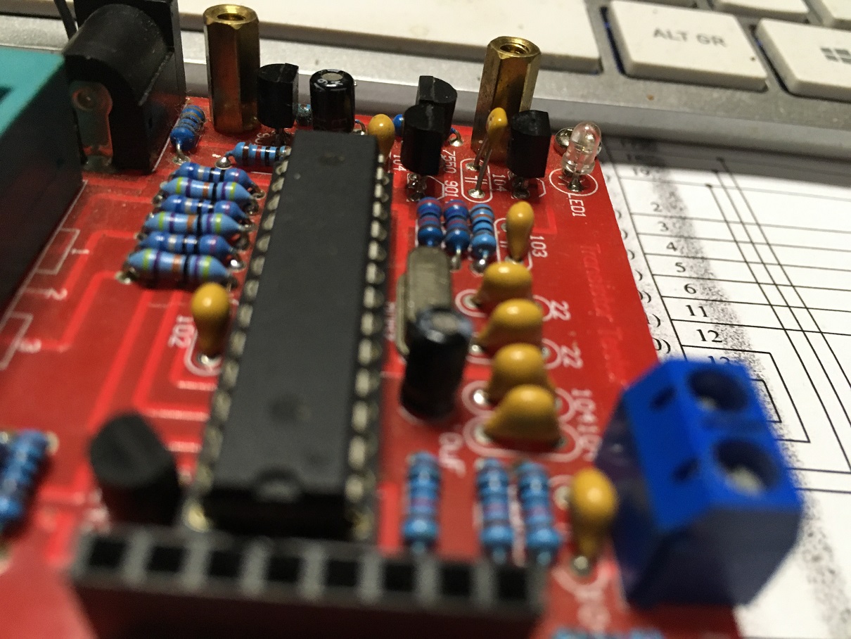
Hallo

Nachdem User Boleslaw J hier eine Adapterplatine vorgestellt hat,
beschäftige ich mich wieder mit dem Teil.

Ich wusste, dass ich noch eine "Leiche" im Bestand hatte.
Also habe ich mal gekramt, und auch gefunden!
Es ist ein AY-AT mit bedrahteten Bauteilen.

Damals gab es einen Kurzschluss mit einem Knall weil ein
vagabundierendes Drähtchen sich unter die Leiterplatte des Testers
verirrt hatte.
Ich hatte sämtliche Transistoren getauscht, nichts hat geholfen.
Immer kam die Ausschrift: "5,01V - Spannung zu gering".
Auf die Idee den Spannungsregler zu prüfen bin ich einfach nicht
gekommen!
Weil ja eben immer die Ausschrift kam "5,01V".
Jetzt (Jahre später) stellte ich eben fest, auch der Regler 7550
war durchgeschlagen. An der CPU lagen >7,5V an!!!!
Der ATMega328P-PU hat das ausgehalten! Es ist erstaunlich was die so
wegstecken können.
Nach auswechseln gegen einen MCP1702-5002 ist alles wieder im Lot.
Mein Multimeter sagt jetzt 5,019 Volt am ATMega328.
Na, das passt doch eher.

Dann wollte ich auch gleich die Referenzspannungsquelle ändern.
Also habe ich einfach 1:1 den TL431 gegen einen LM4040 ausgetauscht.
Denkste, nachdem es nicht funktioniert hatte, stellte ich fest,
dass die beiden unterschiedlichen Typen auch unterschiedliche Footprints
haben. (TO92)
Ich wusste, das LM336 und LM4040 die gleiche Pinbelegung haben.
Also bin ich in meinem jugendlichen Leichtsinn davon ausgegangen, das es
beim TL431 auch so ist.
Nachdem ich auch das richtiggestellt hatte läuft wieder alles prima.
Was mir aber mit erschrecken aufgefallen ist:
https://www.reichelt.de/at/de/shunt-spannungsreferenz-fest-2-5-v-0-1-to-92-lm-4040-aiz2-5-p109411.html?&trstct=pos_15&nbc=1
Kosteten die Dinger nicht mal ca. 60 Cent? Mir war jedenfalls so.

Jetzt bin ich ja mal gespannt, ob Boleslaws Platine mechanisch auf
meinen Tester passt.
Ich habe ja die Version mit bedrahteten Bauteilen, er dagegen mit
SMD-Bestückung.
Bei mir stehen ja ein Paar Bauteile hoch.


Gruss Asko
Angehängte Dateien:
-

tt.jpg
170 KB -

tt1.jpg
180 KB -

adapter.jpg
60 KB -

adapter-x.jpg
170 KB
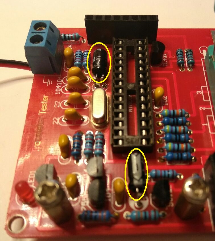
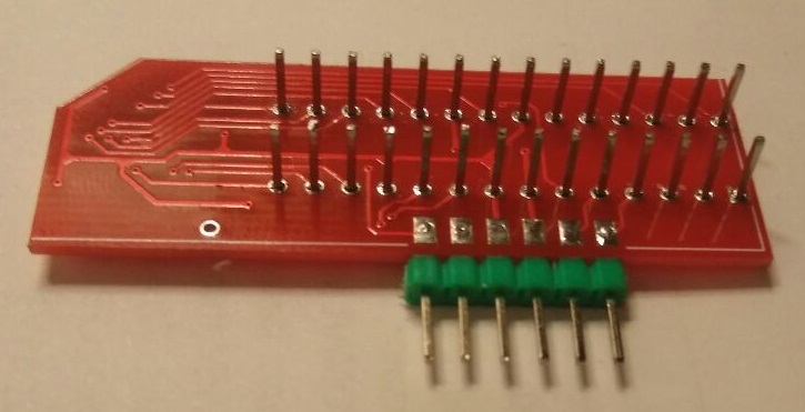
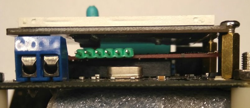
Asko B. schrieb:
> Kosteten die Dinger nicht mal ca. 60 Cent?
auch jetzt noch 60Cent wenn man die SMD Version verwendet ;-)
https://www.ebay.de/itm/124934946426
> Bei mir stehen ja ein Paar Bauteile hoch.
ich besitze beide Versionen, bei der SMD bestückten passt es. bei der
bedrahteten Version passt es auch wenn man die beiden 10µF "flachlegt"
(den einen 10k Widerstand habe ich auf die Unterseite verbannt) und die
Transistoren ggf. "tieferlegt". Wer das chinesische Steckgehäuse
verwendet hat ja genug Platz unter der Platine und könnte auch die Elkos
von unten einlöten. Ich habe außerdem nur Pinns in den Adapter gelötet,
da wäre dann theoretisch noch Platz für eine 2. Platine!
Angehängte Dateien:
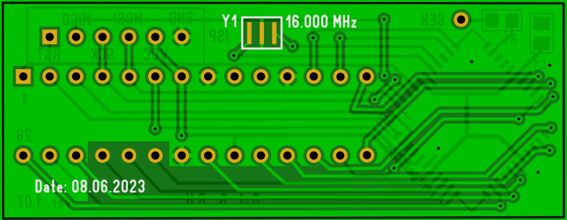
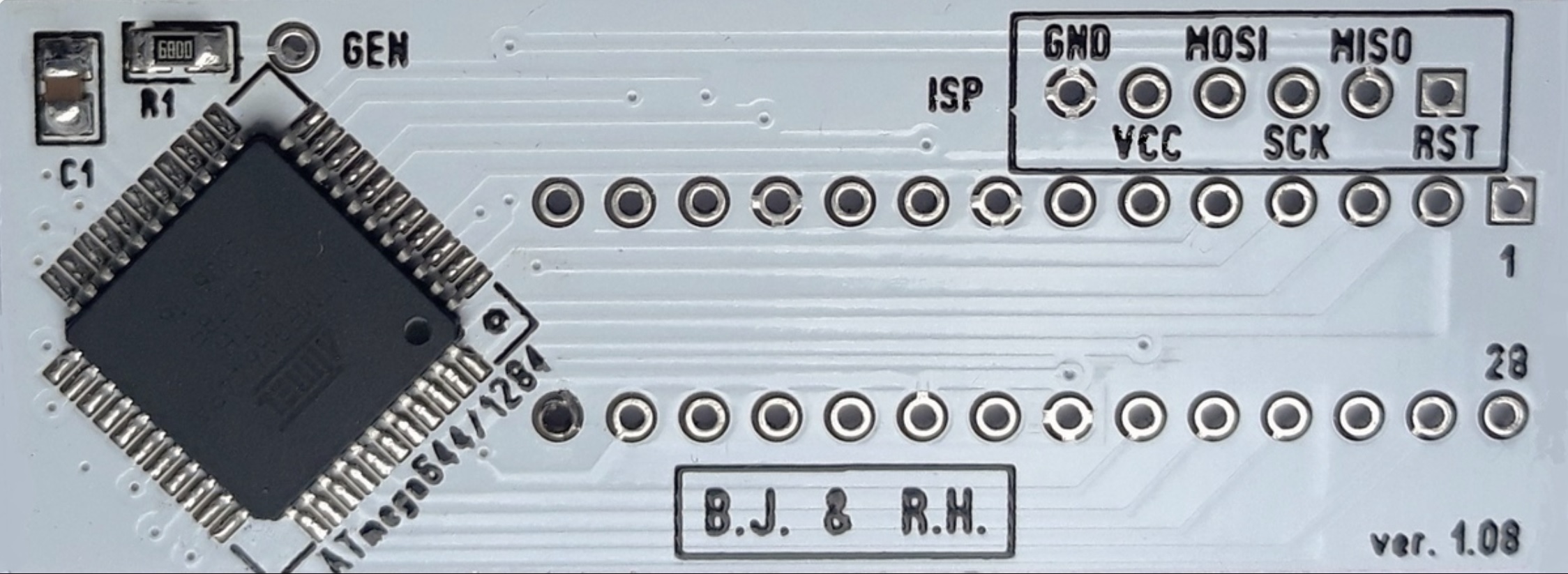
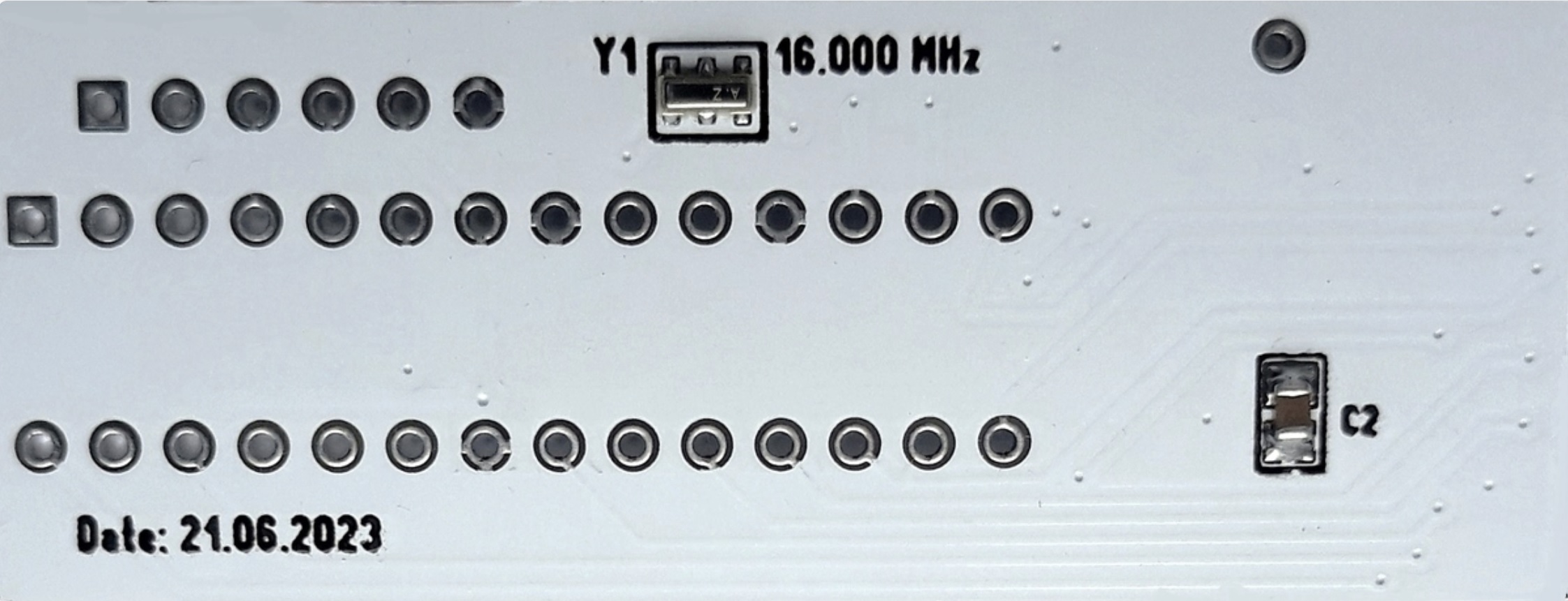
At the request of Asko B. I added a quartz resonator to the adapter.
Hallo
Ich bin verwirrt mit
WITH_SamplingADC im Makefile, wenn es aktiviert ist, was bewirkt es?
ob mit dieser Einstellung bei der Messung der Induktivität die Einheit
von Milihenry (mH) auf Microhenry (µH) geändert werden soll ?
Vielen Dank im Voraus

Yenk, Indonesia :)
Angehängte Dateien:
-

M328-M644.JPG
300 KB
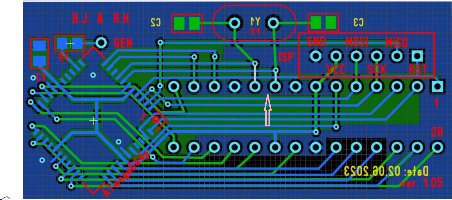
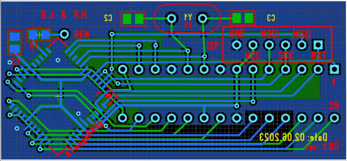
Hallo Boleslaw,

... auf Wunsch von... hört sich ja gut an.    ;-)
Aber es sollte eigentlich einfach nur ein Vorschlag sein.
So das man den schon verbauten 8MHz-Quarz für den M328 drinlassen
kann, und nach umstecken auf den M644 dann halt 16MHz nutzen kann.
Auch dachte ich eher an eine SMD-Ausführung um die Platine nicht
grösser werden zu lassen.
Übrigens müssen dann auch die zwei markierten Leiterbahnen entfernt
werden.

Gruss Asko

Hello Boleslaw,

... at the request of... sounds good ;-)
But it should really just be a suggestion.
So that you can leave the already installed 8MHz-quartz for the M328 in
and after changing to the M644 you can use 16MHz.
I was also thinking of a SMD version so that the board would not be
not to make the board bigger.
By the way, the two marked tracks must also be removed.
be removed.

Greetings Asko
Angehängte Dateien:
-

IMG_0430.JPG
330 KB
@snapper

Bei mir sind die beiden Elkos genauso hoch wie die
Transistoren/Spannungsregler.

Gruss Asko
Auslöten und entweder ganz bis auf die Platine drücken oder auch von der
Unterseite einlöten (auf die Polung achten!). Wenn Du kein chinesisches
Steckgehäuse hast brauchst Du dann aber 4 Abstandshalter. Aber Vorsicht
beim entlöten/löten das Du keine Durchkontaktierungen mit rausreißt und
das die Transistoren nicht überhitzt werden!
Asko B. schrieb:
> By the way, the two marked tracks must also be removed.


There is no need.
Just do not solder pins 9 and 10 of the DIP28 connector.

However, in this version, PCB is universal. When you want to use the 8
MHz quartz resonator installed on the main PCB, just do not solder the
quartz resonator and capacitors to the adapter.
Boleslaws Firmware-Mod und Adapterplatine sind nun im Repo:
- Platine:
https://github.com/madires/Transistortester-Warehouse/tree/master/Hardware
- Firmware-Mod:
https://github.com/madires/Transistortester-Warehouse/tree/master/Firmware/m-firmware
Yenk schrieb:
> Hallo
> Ich bin verwirrt mit
> WITH_SamplingADC im Makefile, wenn es aktiviert ist, was bewirkt es?
> ob mit dieser Einstellung bei der Messung der Induktivität die Einheit
> von Milihenry (mH) auf Microhenry (µH) geändert werden soll ?
> Vielen Dank im Voraus
>
> Yenk, Indonesia :)

Die Sampling ADC Methode erreicht eine schnelle ADC Abtastung durch
Wiederholung der gleichen Messung mit verschobenem Abtastzeitpunkt des
ADC.
Dadurch kann eine Abtastung des Signals im Abstand der Taktfrequenz des
ATmega erreicht werden. Damit ist eine schnelle Abtastung der Ladekurve
eines Kondensators möglich und die Meß-Auflösung kann dadurch bei
kleinen Kondensatoren bis zu 0.01 pF betragen (bei 16 MHz Takt).
Mit der gleichen Methode (SamplingADC) können auch kleinere
Induktivitäten gemessen werden, wenn ein Kondensator mit hoher Güte
(10nF - 30nF) parallel geschaltet wird.
Dann wird aus der Induktivität ein Schwingkreis. Aus der Schwingfrequenz
wird dann die Induktivität berechnet. Daneben wird auch die Güte des
Schwingkreises bestimmt. Bei einer hohen Güte des parallel geschalteten
Kondensators ist die Güte des Schwingkreises praktisch identisch mit der
Güte der Induktivität.
Der parallel geschaltete Kondensator wird bei der Induktivitätsmessung
automatisch erkannt.
Angehängte Dateien:
-

Adapter_plus_quartz.jpg
420 KB
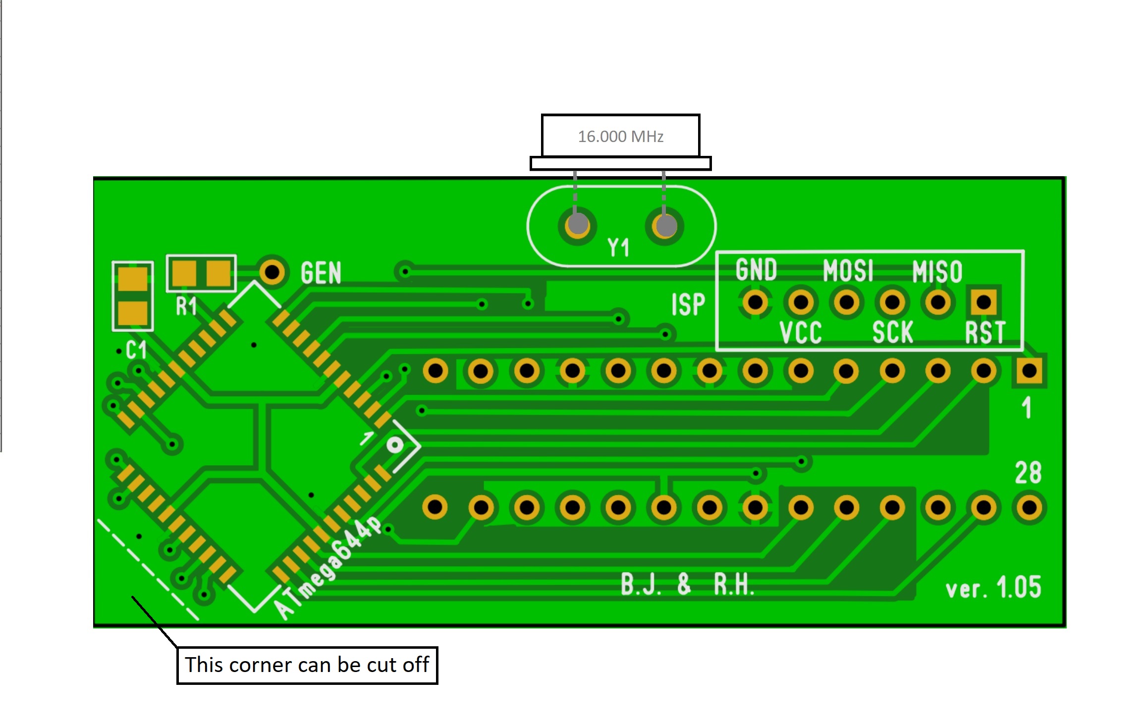
If it is not possible to mount a quartz resonator either on the bottom
layer of the PCB or on the top layer, you can try to place it on the
side of the PCB, as in the attached figure.
Angehängte Dateien:

Asko B. schrieb:
> I was also thinking of a SMD version so that ...
> not to make the board bigger.

To reduce the dimension of the adapter, I moved the quartz resonator Y1
and capacitors C2, C3.
Angehängte Dateien:
-

Adapter_-_pins_warning.jpg
200 KB
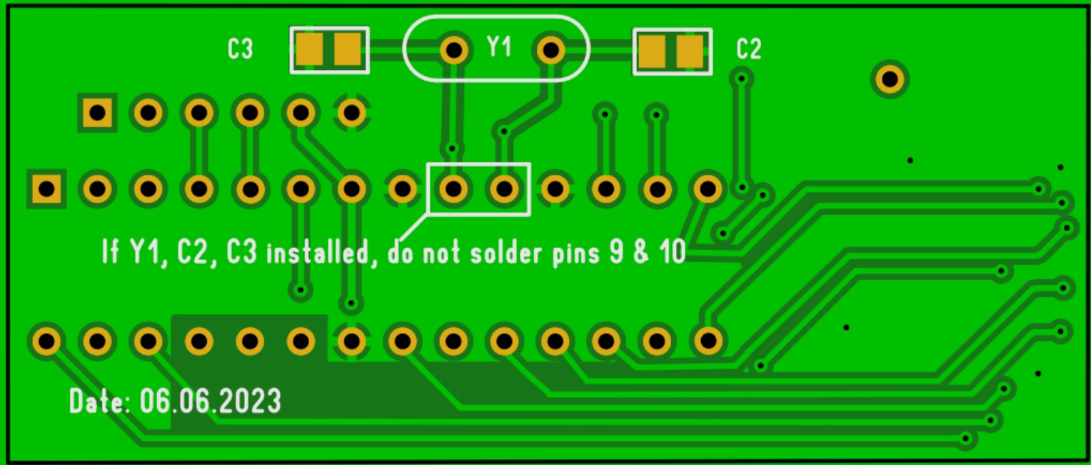
I added the inscription:
"If Y1, C2, C3 installed, do not solder pins 9 & 10"
Two suggestions:
* Make Y1 a SMD version
* Cut the tracks to the adapter pins. Not soldering them does not make
sure, that there is no contact at all. You might need to cut off the
adapter pins before soldering.
Carsten W. schrieb:
> Two suggestions:
> * Make Y1 a SMD version
> * Cut the tracks to the adapter pins. Not soldering them does not make
> sure, that there is no contact at all. You might need to cut off the
> adapter pins before soldering.

Thank you for your valuable suggestions.
The basic design of this adapter in the source version (.lay6) is placed
in the Markus R. repository.
Everyone can download and modify this project for their own needs and
self-assembly capabilities.
I'm only an observer in this thread and I do not intend to use the
adapter.

I'm just suggesting some improvements, since it's not good design
practice to make a circuit's functionality dependent on whether two pins
of a larger component are soldered or not.

People who a not familiar with the circuit will search themselfs to
exaustion if the oscillator is not working as intended or will stop to
work at some point. They will simply overlook these two pins. And like I
wrote before: Even if not soldered, there is no guarantee at all, that
those plated holes and pins will stay out of contact forever.
...sry, a little bit more soup in the brain then after primary school
may be expected by persons using such testers AND at least in
combination with this adapter. But anyway this discussion might be OT.

Klaus.
Angehängte Dateien:
-

328er-Optokoppler-in-Fassung.jpg
210 KB -

2te-Fassung-von-unten.jpg
190 KB -

Adapter-eingesteckt.jpg
150 KB -

Seitlich-auf-Sandwich-und-Quarz.jpg
120 KB -

IR-Code.jpg
150 KB -

tek_HARDWARE-SPI-644.png
18 KB -

tek_BITBANG-SPI-644.png
17 KB -

tek_BITBANG-SPI-328.png
16 KB -

tek_IR-Signal.png
10 KB
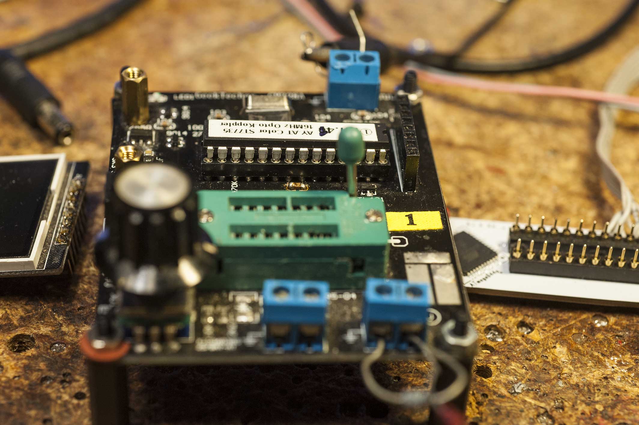
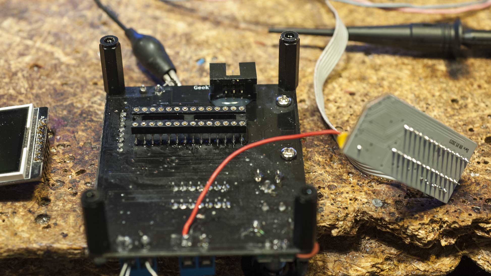
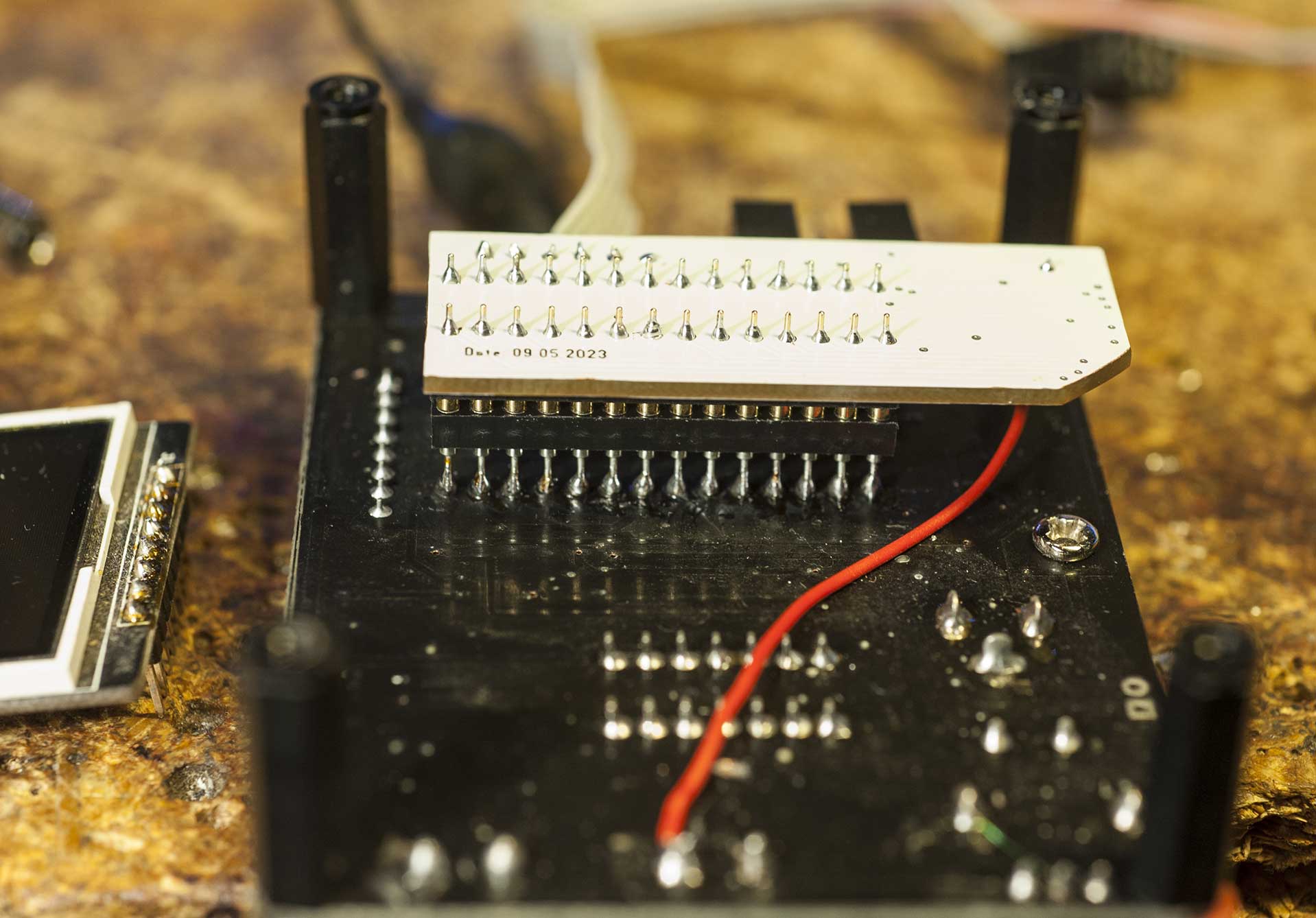
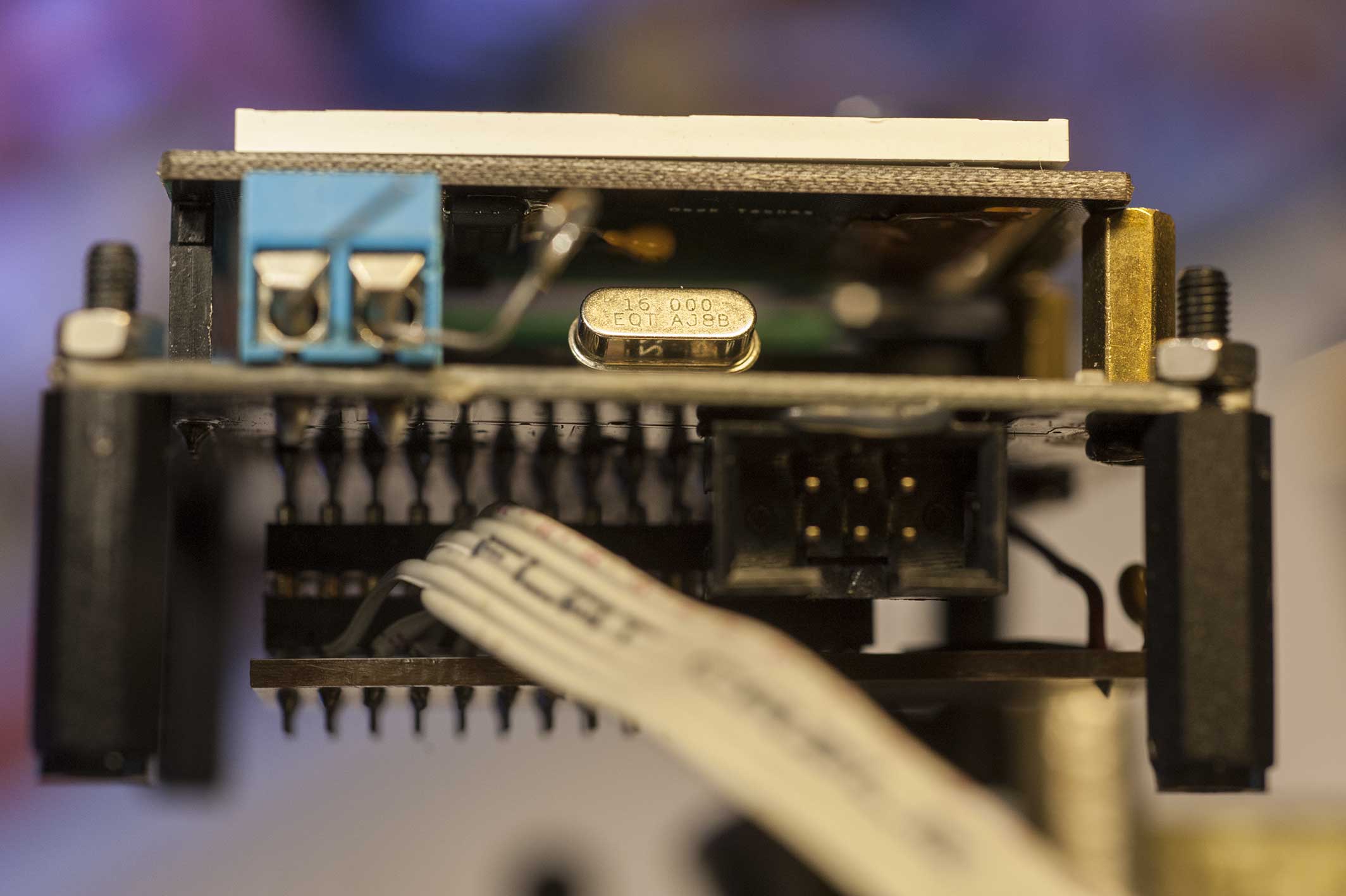
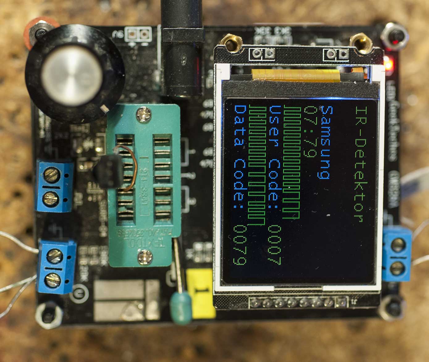
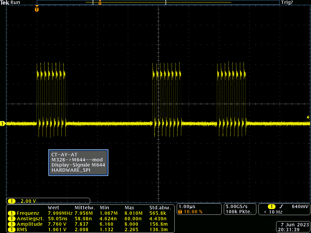

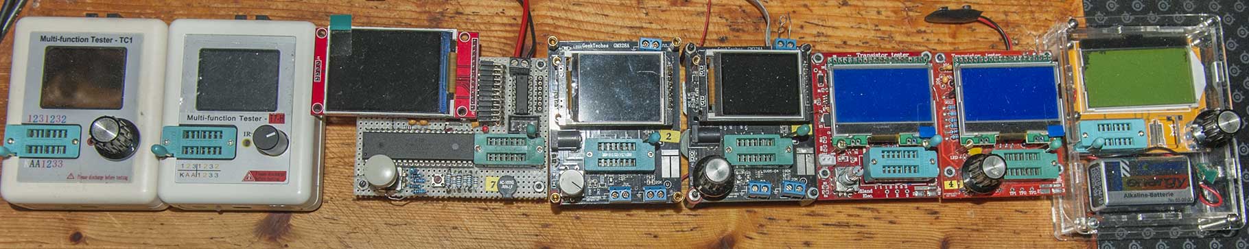
... von Anfang an gefiel mir Boleslaw 's Projekt mit dem
Erweiterungs-Adapter.

Im Laufe der letzten Jahre kamen immer mehr Messmöglichkeiten für den
Componenten-Tester hinzu, z. B. auch ein kleine Adapter zum Test von
Optokopplern.

Der begrenzte Speicherplatz beim Atmega328 zwang nun zum Auswählen der
Funktionen und zum Vorhalten mehrere 328er mit unterschiedlichen
Funktionen, die bei Bedarf dank IC-Fassung Auswechselbar waren.

Der o.a. 644er/1284er Adapter bringt da Abhilfe.

Boleslaw war so freundlich, mir 2 PCB 's zu überlassen. Am Montag waren
die in der Post und ich habe gleich 'nen Atmege644 aufgelötet.

Der Platz unter dem Display ist nicht so üppig und ich endschied mich,
den Adapter von unten mittels einer zweiten IC-Fassung einsteckbar
anzubringen.

Zunächst gab es ein Problem bei der Inbetriebnahme - keine Anzeige auf
dem Display? Eine eingesteckte LED in den ZIF-Testsockel zeigte durch
ihr Aufflackern das das Programm schonmal lief. Am Oscilloscope sah man
auch die Impulse der Display-Ansteuerung.

Zum Glück habe ich ja zwei dieser Tester und das andere Display
funktionierte auf Anhieb. Da beide Displays an den 328er Controllern
arbeiten, stellte sich durch Vergleich der Ansteuer-Impulse heraus, das
nur eins dem schnelleren HARDWARE-SPI folgen konnte. Habe dann zum Test
den Adapter auf BITBANG-SPI umgestellt und das "langsamere" Display
funktioniert nun auch am 644er Adapter.

Der momentane Füllstand des Atmega644 liegt bei Program: 74,4%, Data:
7,0% und EEPROM: 73,5%

Der zweite Adapter bekommt dann einen Atmega1284!

Gruß Horst


... from the beginning I liked Boleslaw's project with the expansion
adapter.

Over the last few years, more and more measurement options for the
component tester have been added, e.g. B. also a small adapter for
testing optocouplers.

The limited storage space of the Atmega328 now forced the selection of
the functions and the provision of several 328s with different
functions, which were interchangeable if necessary thanks to the IC
socket.

The 644/1284 adapter mentioned above will help.

Boleslaw was kind enough to let me have 2 PCB's. They were in the mail
on Monday and I immediately soldered an Atmege644 on.

The space under the display is not that plentiful and I decided to
attach the adapter from below using a second IC socket.

At first there was a problem when starting up - nothing on the display?
An LED plugged into the ZIF test socket showed that the program was
already running by its flickering. On the oscilloscope you could also
see the impulses of the display control.

Luckily I have two of these testers and the other display worked right
away. Since both displays work on the 328 controllers, a comparison of
the control pulses showed that only one could follow the faster HARDWARE
SPI. I then switched the adapter to BITBANG-SPI for the test and the
"slower" display now also works on the 644 adapter.

The current fill level of the Atmega644 is at Program: 74.4%, Data: 7.0%
and EEPROM: 73.5%

The second adapter then gets an Atmega1284!

Greeting Horst
Angehängte Dateien:
I gratefully accept constructive criticism.
Horst O. schrieb:
> Der Platz unter dem Display ist nicht so üppig und ich endschied mich,
> den Adapter von unten mittels einer zweiten IC-Fassung einsteckbar
> anzubringen.

Prima Idee!
Da wäre ich jetzt nicht drauf gekommen.    ;-)

Gruss Asko
Horst O. schrieb:
> Der zweite Adapter bekommt dann einen Atmega1284!

Gerade frisch eingetroffen.
Nach dem Motto wenn schon, denn schon.

Ich habe ja auch von Boleslaw zwei Platinchen bekommen.

Aber einlöten werde ich die nicht gleich, da muss ich
eine "ruhige Minute" abwarten. Sonst zitter ich den
irgendwohin, aber nicht dahin wo er hin soll.

Jetzt muss ich erst mal die Compilierumgebung wieder flott machen.
Ist ja schon ein paar Jahre her, wo ich damit rumgemacht hatte.
Mal sehen ob ich das mit Win11 hinbekomme.
Oder würde das auf einem Raspi auch funktionieren?
Ich bin aber nicht so der Linux-Freak.
Wegen SSD-Absturz und später Rechnerwechsel ist so gut wie nix
mehr da. Selbst meine eigenen Layouts habe ich hier aus dem
Forum wieder zurückgelesen.   ;-)

Ich hab den gesamten Faden jetzt mal neu von vorne bis hinten gelesen.
Da hab ich über 2 Wochen für gebraucht.
Angestachelt wurde ich von Boleslaw und R. H. mit Ihrem Addon-Board.
Deswegen hatte ich auch meine "Leiche" wieder herausgekramt.
Ich hatte mir damals ein fertiges Board mit M644 zugelegt, und der
AY-AT verschwand in irgendeiner Kiste. Aber beschriftet mit "T-Tester".
Deswegen musste ich auch nicht besonders lange suchen.

Beruflich bedingt, ich habe beruflich nichts mit Elektronik zu tun,
hatte ich auch jahrelang gar keine Zeit/Ambitionen/Lust die Sache
weiter zu verfolgen.
Jetzt habe ich wieder Zeit (und Lust) für sowas.

Genau zu dem Zeitpunkt der Wiederinbetriebnahme des AY-AT
kam eine Bekannte mit einer defekten Pumpensteuerung.
Und siehe da, ich konnte einen defekten Elko ausfindig machen.
Ersatzteil war bei der heutigen Lieferung dabei.
Mal sehen ob das Ding morgen funktioniert.

Bevor ich hier weiter schreibe muss ich mich wohl erst einmal
bei Boreslaw persönlich bedanken.

Gruss Asko
Angehängte Dateien:
-

photo_22.jpg
75 KB -

photo_23.jpg
32 KB
Horst O. schrieb:
> Der Platz unter dem Display ist nicht so üppig und ich endschied mich,
> den Adapter von unten mittels einer zweiten IC-Fassung einsteckbar
> anzubringen.

hi,
total überflüssiger Aufwand und zudem sieht die Lösung nicht gerade gut
aus.
Auch mit dem etwas dickeren PCB Material von Boleslaws Adapter ist da
noch genügend Platz unter dem Display wenn man den Adapter nur mit
kurzen Stiften bestückt so wie in meinen Bildern vom 02.06. zu sehen.
Es tut mir leid, dass ich diesen ungeheuer langen Thread mit meinem
Anliegen einfach kapere.
Hintergrund ist, dass ich die Transistortester-Entwicklung einfach ein
paar Jahre nicht verfolgen konnte.

Ich hatte ursprünglich eine Platine mit ATmega328 und DOGM-Display und
PWM-Helligkeitsknopf. Moritz Augsburger hatte das entwickelt und hier
überflüssige Platinen verkauft.
Der Transistortester funktionierte hervorragend, nur war der Einbau in
ein Gehäuse sehr schwierig (Zugänglichkeit der Bedienknöpfe).

Daher habe ich das ganze Projekt demontiert und mir folgenden von
Reichelt gekauft: JOY-IT LCR-T7 Komponententester

kurzes Fazit:
- Grafik-Display großes Plus
- LiPo-Akku mit USB-Lademöglichkeit schön und gut
- Messstrippen etwas billig
- Gehäusetechnik hakt (Bedienknopf)
ABER: Es können keine J-FETS gemessen werden! Es wird immer "Z-Diode"
angezeigt. Messgenauigkeiten überhaupt etwas fraglich, es wird hier und
da auf "falsche Bauteiltypen eingerastet", so kommt es mir vor.

Ich habe lieber einen Transistortester, bei dem ich Hardware UND
Software genau kenne.

Frage (nach so vielen Jahren der Abstinenz vom Thema): Was muss ich tun,
um einen genauen, zuverlässigen Tester zu bekommen, der robust in ein
Gehäuse einbaubar ist? Notfalls entwerfe ich mir selbst eine Platine mit
KiCAD, die ich bei JLCPCB oder PCBway fertigen lasse.
Ich habe nur den Anschluss zu der neuesten Hardwareversion verloren.
"Boleslaw" sagt mir nichts. Kennt noch jemand die Vorteile von
DOGM-Displays? Die sind taghell und glasklar, aber sehr zerbrechlich.
Oder den Ansatz von Moritz Augsburger?

Jegliche Hilfe ist willkommen!

Christian
Angehängte Dateien:
-

ATM.JPG
26 KB
Christian S. schrieb:
> "Boleslaw" sagt mir nichts.

Bei dem Adapter Projekt von Boleslaw und mir geht es um den Austausch
des ATM328 gegen den ATM644 wegen des größeren Speichers und Boleslaws
Firmware zum messen von IR Komponenten. Die Platine passt aber nur zum
AY-AT Tester und ggf. anderer Tester mit gesockeltem ATM328 siehe die
Beiträge ab 28.03.2023!
Als DIY Projekt mit ATM644 kenne ich nur den MEGA4GSL -->
Beitrag "Re: Transistortester AVR"
Dein LCR-T7 sollte auch einen ATM644 haben, schon mal mit einer anderen
Firmware versucht? Sitzt da ein ATM324 drin lässt er sich gegen den
ATM644 problemlos austauschen (vorausgesetzt man kann SMD löten)!
Vielen Dank R. H., die Fingerzeige helfen mir schon mal.

Ich bin im Allgemeinen firm mit avr-gcc, WinAVR, avrdude und so weiter.
Löten von SMD-ICs bekomme ich auch hin.
Nur mit dem Weg, den das Hardwareprojekt im Groben und Ganzen genommen
hat, kenne ich mich weniger aus.

Ich nehme an, dass "AY-AT" mal eine kommerzielle erhältliche Hardware
mit ATmega328 war, oder?

Beim compilieren der Firmware wird ja allgemein folgendes gemacht:
1 | cflags+=-Dhardwarefeature1 |
2 | cflags+=-Dhardwarefeature2 |
3 | ...usw. |
Wo kann ich nachlesen, welche -Dhardwareflags mein LCR-T7 benötigt?

Danke schon mal im Voraus!

Christian
Christian S. schrieb:
> Jegliche Hilfe ist willkommen!

Hallo,

ich verfolge die Diskussion hier auch eher sporadisch, aber ich denke
die beste Dokumentation, um auf den "neuesten" Stand zu kommen, ist
immer noch die "offizielle" Doku
https://raw.githubusercontent.com/Mikrocontroller-net/transistortester/master/Doku/trunk/pdftex/german/ttester.pdf
und der Artikel
https://www.mikrocontroller.net/articles/AVR_Transistortester
Wenn es um konkrete HW geht, musst Du Dir überlegen, welche
Zusatzfunktionen (z.B. LC-Messung etc.) Dir wichtig sind und dann z.B.
diese Diskussion vom neuesten Beitrag hin zu älteren Beiträgen auf ein
Platinenlayout durchforsten - oder hier nochmal fragen.
Christian S. schrieb:
> Jegliche Hilfe ist willkommen!

Hallo Christian,
Dein Tester hat einen kleinen Haken.
Dort wird ein extra Controller für die Tastensteuerung benutzt.
Bei Softwareänderungen ist dieser Chip entweder neu zu programmieren
oder zu entfernen und durch eine Transistorschaltung zu ersetzen.
Egal ob jetzt da ein M324 oder M644 drin werkelt.
Genauere Hinweise können Dir Markus(madires) oder Horst O.(obelix2007)
geben.
Im eevblog zum gleichen Thema hat User Indman mal eine Liste
der meistgehandelten Transistortester veröffentlicht.
Allesamt Made in China.
Die hänge ich mal an.

Gruss Asko
Christian S. schrieb:
> Jegliche Hilfe ist willkommen

Hallo Christian,

Asko hatte erste Hinweise gegeben - um die Software zu ändern, muß
zunächst die Hardware geändert bzw. ergänzt werden:

Die Einschaltdauer wird von einem kleinen Chip gesteuert und ist nicht
mit der Standartsoftware kompatibel. Man kann den neu programmieren oder
gegen eine kleine 2-Transistorschaltung tauschen. Desweiteren muss ein
Programmier-Steckverbinder angebracht werden.

Beitrag "Re: Transistortester AVR"

Abhängig von deiner bevorzugten Software (Karl-Heinz Kübbeler KH-1.13
oder Markus Reschke CT-m1.49) ist die Konfiguration etwas
unterschiedlich - bei KH nur über das Makefile, bei Markus über
Makefile, config.h und config_644.h.

https://github.com/madires/Transistortester-Warehouse/tree/master/Firmware/m-firmware

Gruß Horst
Horst O. schrieb:
> Die Einschaltdauer wird von einem kleinen Chip gesteuert und ist nicht
> mit der Standartsoftware kompatibel. Man kann den neu programmieren oder
> gegen eine kleine 2-Transistorschaltung tauschen. Desweiteren muss ein
> Programmier-Steckverbinder angebracht werden.

Ich habe im EEVblog ein wenig weiter gelesen.
Es gibt wohl mittlerweile ein paar Ausführungen die diesen
Chip nicht mehr benutzen.
Dafür aber ein paar Ausführungen, die einen anderen Controller
verwenden, der (noch) nicht "upgradable" ist.
Und die dazu noch "Fake" beschriftet sind.
Es betrifft wohl die Boards, die mit 32-poligen Controller
ausgeliefert werden.
das "kann" ein originaler Atmel ATMega328 sein, muss aber nicht.

Es wird Christian nichts weiter übrig bleiben nach dem
Erhalt des Gerätes, das Ding erst mal aufzuschrauben und nachzusehen.
Und am besten Fotos machen und hier teilen.
Und dann zu entscheiden, behalte ich es, oder schick ich es als
unbrauchbar zurück.

Es gibt ja von den ganzen Testern eine schier unendliche
Variantenvielfalt, gerade bei den als TC-xy bezeichneten.
Ich hatte ja letztens eine Liste hier angehängt.
Die war von 2021, die hat sich ja mittlerweile mehrfach überholt.
Ich hänge mal die Liste von Ende letzten Jahres an.
(falls die noch jemand nicht kennt)
Und es kommen immer noch neue Clone hinzu.
Letztens fand ich dieses hier, was ich noch nicht kenne:
https://www.amazon.de/Transistor-Tester-Frequenz-Englische-Vollversion/dp/B0BTT5H1CC/ref=rvi_sccl_2/259-6963354-0944345
Dort sind im Gegensatz vom AY-AT alle Schraubanschlüsse
auf der User-zugewandten Seite.
ich bin ja mal gespannt, was da für ein Controller drauf ist.

Gruss Asko
Hello everyone, could you help me to modify the language of the
TransitorTest. Since when you want to compile it with WinAVR it throws
an error
I leave a block of notes for you to review the error..
Anything you want to modify or compile don't do
I have uploaded modification video
DiagSoftware schrieb:
> Since when you want to compile it with WinAVR it throws
> an error
> I leave a block of notes for you to review the error..

Some time ago my Windows PC came up with the same error (for short:
===================================================================
      0 [main] sh 5812 sync_with_child: child 1264(0x1D4) died before
initialization with status code 0xC0000142

  35305 [main] sh 5812 sync_with_child: *** child state waiting for
longjmp)
===================================================================

Start a Windows Console and type "make --version".
make should answer with the following message:
===================================================================
C:\Users\md\console2>make --version
GNU Make 4.2.1
Built for Windows32
Copyright (C) 1988-2016 Free Software Foundation, Inc.
License GPLv3+: GNU GPL version 3 or later
<http://gnu.org/licenses/gpl.html>;
This is free software: you are free to change and redistribute it.
There is NO WARRANTY, to the extent permitted by law.
===================================================================

If you get a different prompt, you're having the same problem that I
had, i.e. the wrong make utility.

I traced down this error to a make utility that was incompatible with
avr-gcc since it doesn't understand the gcc make syntax, it issues the
cited error messages. The Delphi IDE that I had installed, changed -
without warning of course - the default path environment variable to
point to its own make.exe. So when I called "make xyz", the Delphi
make.exe was run.

So, imho, what you can try is to edit your path variable to put the
avr-gcc related parameters before any other compiler's perameters. You
might also try to call make and all other GNU utililities with a fully
specified path. I don't know if thats possible with winavr. In any case,
the test call of make must give the result above.

What I finally did is to cut the gordian knot all together, and I now
use the Windows Subsystem for Linux to compile avr-gcc source files.
When you grant access to your linux user folders, where avr-gcc stores
its results, you can read the compiled files from windows.

I hope this helps,
derri
Marcel D. schrieb:
> DiagSoftware schrieb:
>> Since when you want to compile it with WinAVR it throws
>> an error
>> I leave a block of notes for you to review the error..
>
> Some time ago my Windows PC came up with the same error (for short:
> ===================================================================
>       0 [main] sh 5812 sync_with_child: child 1264(0x1D4) died before
> initialization with status code 0xC0000142
>
>   35305 [main] sh 5812 sync_with_child: *** child state waiting for
> longjmp)
> ===================================================================
>
> Start a Windows Console and type "make --version".
> make should answer with the following message:
> ===================================================================
> C:\Users\md\console2>make --version
> GNU Make 4.2.1
> Built for Windows32
> Copyright (C) 1988-2016 Free Software Foundation, Inc.
> License GPLv3+: GNU GPL version 3 or later
> <http://gnu.org/licenses/gpl.html>;;
> This is free software: you are free to change and redistribute it.
> There is NO WARRANTY, to the extent permitted by law.
> ===================================================================
>
> If you get a different prompt, you're having the same problem that I
> had, i.e. the wrong make utility.
>
> I traced down this error to a make utility that was incompatible with
> avr-gcc since it doesn't understand the gcc make syntax, it issues the
> cited error messages. The Delphi IDE that I had installed, changed -
> without warning of course - the default path environment variable to
> point to its own make.exe. So when I called "make xyz", the Delphi
> make.exe was run.
>
> So, imho, what you can try is to edit your path variable to put the
> avr-gcc related parameters before any other compiler's perameters. You
> might also try to call make and all other GNU utililities with a fully
> specified path. I don't know if thats possible with winavr. In any case,
> the test call of make must give the result above.
>
> What I finally did is to cut the gordian knot all together, and I now
> use the Windows Subsystem for Linux to compile avr-gcc source files.
> When you grant access to your linux user folders, where avr-gcc stores
> its results, you can read the compiled files from windows.
>
> I hope this helps,
> derri

C:\WINDOWS\system32>make --version
GNU Make 3.81
Copyright (C) 2006  Free Software Foundation, Inc.
This is free software; see the source for copying conditions.
There is NO warranty; not even for MERCHANTABILITY or FITNESS FOR A
PARTICULAR PURPOSE.

This program built for i386-pc-mingw32
I have solved the compilation using Win7.. The problem I have now is
that when I changed the language some characters disappeared...

Link video the error

https://mega.nz/file/qtIGnRwD#0xP_Qwhrt2_Yz4XMayIOXxPZRly7LgNIcMBDz51E0OA
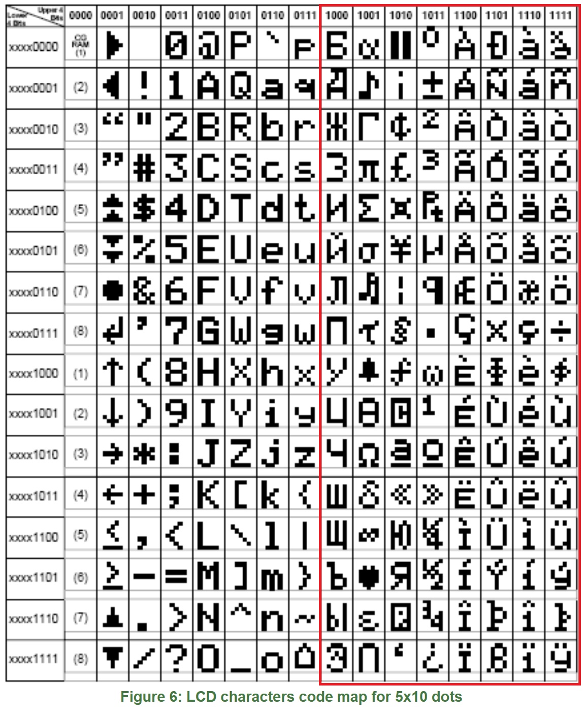
DiagSoftware schrieb:
> when I changed the language some characters disappeared...

This may be a feature of this 2x16 LCD display, which in the second half
of the character table (codes 128 to 255) does not contain the
characters used here, instead has spaces, filled with bytes of 0xFF.
Boleslaw J. schrieb:
> DiagSoftware schrieb:
>> when I changed the language some characters disappeared...
>
> This may be a feature of this 2x16 LCD display, which in the second half
> of the character table (codes 128 to 255) does not contain the
> characters used here, instead has spaces, filled with bytes of 0xFF.

With the default language it works perfectly. It only fails when I
select another language already modified
DiagSoftware schrieb:
> With the default language it works perfectly. It only fails when I
> select another language already modified

Quote from the file "language-dependent_characters.h":

  #elif defined LANG_SPANISH
      PIX_a_acute            /* 0x80 a_acute  e1 */
      PIX_c_cedil            /* 0x81 c_cedil  e7 */
      PIX_e_acute            /* 0x82 e_acute  e9 */
      PIX_i_acute            /* 0x83 i_acute  ed */
      PIX_o_acute            /* 0x84 o_acute  f3 */
      PIX_u_acute            /* 0x85 u_acute  fa */
      PIX_u_uml              /* 0x86 u_uml    fc */
      PIX_A_acute            /* 0x87 A_acute  c1 */
      PIX_E_acute            /* 0x88 E_acute  c9 */
      PIX_I_acute            /* 0x89 I_acute  cd */
      PIX_O_acute            /* 0x8a O_acute  d3 */
      PIX_U_acute            /* 0x8b U_acute  da */
      /* PIX_a_super */           /* 0x8c a_super     */
      /* PIX_o_super */           /* 0x8d o_super     */
      /* PIX_n_tilde */           /* 0x8e n_tilde     */
      /* PIX_N_tilde */           /* 0x8f N_tilde     */
      /* PIX_updown_exclam */     /* 0x90 updown_exclam  */
      /* PIX_updown_question */   /* 0x91 updown_question */


All the above listed characters of the Spanish alphabet are included in
the second half of the ASCII character table.
The default language (English) does not use them. Change the LCD to the
correct one or use the default language.
DiagSoftware schrieb:
> that when I changed the language some characters disappeared...

With the "k" software only the cyrillic characters are supported for a
special version of character displays (2x16 lines).

For all other languages besides Russian and Ukrainian, special
characters are replaced by ASCII characters for the character displays.
Please see the lines 405 to 533 in lcd_defines.h! Language-dependent
special characters are only supported for graphic displays.

For the spanish language (langSPANISH.h) special characters are not
implemented now. Please see the czech language (langCZECH.h) how special
characters must be handled correctly. You can find the supported special
characters for all languages in the file fonts/std_defines.h ! But you
should keep in mind, that all special characters are only operative for
graphical displays. For character displays these special characters are
replaced by ASCII characters automatically.

So I don't understand, why your character display make problems with
other languages. Probably you can send your Makefile to my email
address, which you can find at the title page of the documentation. I
will send you the compiled files back and can also test them with other
hardware.
Angehängte Dateien:
-

LCD_characters_code_map.jpg
450 KB
For such a popular language in the world as Spanish, it is worth
implementing this language into the T-Tester program.
Most character LCD displays include Spanish characters in their maps (in
addition to Cyrillic and other national characters).
Since it is possible to implement the Cyrillic alphabet, it is also
possible to implement the Spanish.
In this forum, there are certainly many developers who use Spanish on a
daily basis ( in addition to C :) ) who could (and should) do so.
Don't wait for someone to do it for you!
Boleslaw J. schrieb:
> For such a popular language in the world as Spanish, it is worth
> implementing this language into the T-Tester program.
> Most character LCD displays include Spanish characters in their maps (in
> addition to Cyrillic and other national characters).
> Since it is possible to implement the Cyrillic alphabet, it is also
> possible to implement the Spanish.
> In this forum, there are certainly many developers who use Spanish on a
> daily basis ( in addition to C :) ) who could (and should) do so.
> Don't wait for someone to do it for you!

Excellent, just got to work
Kleine Erfrischung für die Sommerpause:

v1.50m
- Temporäre Option UI_PROBE_REVERSED_X entfernt, da nicht länger
benötigt.
- Option zur Ausgabe vom Batteriestatus in der letzten Zeile nach der
Ergebnisanzeige (UI_BATTERY_LASTLINE).
- Option zur Anzeige eines kleinen Batteriesymbols für den
Batteriestatus (UI_BATTERY).
- Batterie-Symbole in den meisten Zeichensätzen ergänzt. Und manche
Zeichensätze mit Testpin-Nummern mit verdrehtem Vordergrund/Hintergrund
erweitert.
- Option für langen Reset-Puls für LCD-Controller NT7538 im
ST7565R-Treiber eingebaut (LCD_LONG_RESET).
- Test-Funktion für Fotodioden (SW_PHOTODIODE).
- Option für seitenweises Blättern von Menüs (UI_MENU_PAGEMODE,
Vorschlag von indman@EEVblog). Beschleunigt die Menübedienung bei
Grafikanzeigen.
- Zwei neue Farben für colors.h (COLOR_PALE_GREEN, COLOR_PALE_RED,
Vorschlag von .RC.@EEVblog).
- Brasilianisch-portugiesische Texte aktualisiert (Dank an
wandows@EEVblog).
- Russische Texte aktualisiert (Dank an indman@EEVblog).
- Polnische Texte #2 aktualisiert (Dank an Jacon@EEVblog).
- Spanische Texte aktualisiert (Dank an pepe10000@EEVblog).

Download auf:
-
https://github.com/madires/Transistortester-Warehouse/tree/master/Firmware/m-firmware
- https://github.com/kubi48/TransistorTester-source/tree/master/Markus
(demnächst)
Hi Boleslaw,

hast Du für Markus' neue 1.50 FW-Version schon eine Anpassung für Deinen
AY-AT auf Admega644/1284 Adapter?

Gruß Horst

Hi Boleslaw,

Do you already have an adjustment for your AY-AT to Admega644/1284
adapter for Markus' new 1.50 FW version?

Greeting Horst
Horst O. schrieb:
> hast Du für Markus' neue 1.50 FW-Version schon eine Anpassung für Deinen
> AY-AT auf Admega644/1284 Adapter?

Hi, Obelix
ich dachte bisher immer das wäre eh eine spezielle
Anpassung der Software.

Gruss Asko
Asko B. schrieb:
> spezielle

... schon „speziell“, aber läuft auch auf anderen 644/1284er Testern,
man muss halt die Portbelegungen anpassen.

Gruß Horst
Angehängte Dateien:
-

AY-AT-644-Adapter-SONY-SIRC-IR-Code.jpg
110 KB -

CT-1.49_M644_mod_Lochraster-ILI9342.JPG
270 KB -

CT-1.49_M644_mod_Lochraster-ILI9342-Grafik-Impulse.jpg
220 KB -

CT-1.49_M644_mod_Lochraster-ST7735.jpg
230 KB -

Lochraster-IR-Panasonic-Kaseikyo.jpg
240 KB -

Lochraster-SONY-SIRC-IR-Code.jpg
220 KB -

T7-H-SONY-SIRC-IR-CODE.jpg
190 KB -

Logitech-Universal-RC_web.jpg
62 KB
... läuft also auf versch. Testern:

Gruß Horst
Horst O. schrieb:
> Hi Boleslaw,
>
> Do you already have an adjustment for your AY-AT to Admega644/1284
> adapter for Markus' new 1.50 FW version?

I'm working on it.

Greetings,
Boleslaw
Total novice here.

Could anyone help me understand what might be needed to adapt or
integrate this for use with the flipper zero? Is this a totally foolish
thought?

I figure with the GPIO and LCD alone, an addon board could be created
using a standalone ATmega, etc... additionally, you can optionally set
5v on GPIO, which iirc would be of benefit.

I saw other project that use the STM32 to lesser effect and seeing that
the Flipper Zero uses the STM32WB55, I was curious if that could be
leveraged too.

welcoming any input, even if it's confirming this as a foolish idea.
...why do you want to use this if you have no clue, where is the benefit
for you? Just because you have the proto board?

Klaus.
The C. schrieb:

> Could anyone help me understand what might be needed to adapt or
> integrate this for use with the flipper zero? Is this a totally foolish
> thought?

The OSHW Transistortester firmwares are optimized for the ATmega
architecture and it would take a major effort to port them to another
MCU family.

> I figure with the GPIO and LCD alone, an addon board could be created
> using a standalone ATmega, etc... additionally, you can optionally set
> 5v on GPIO, which iirc would be of benefit.

Both OSHW firmwares already support serial output, and the m-firmware
additionally remote commands. However, controlling the Transistortester
from another gadget with a small screen doesn't provide any benefit over
using the tester with a screen directly, IMHO.

> I saw other project that use the STM32 to lesser effect and seeing that
> the Flipper Zero uses the STM32WB55, I was curious if that could be
> leveraged too.

The Flipper Zero costs 170 bucks. A Transistortester clone is much less.
It doesn't make much sense to follow that route.

BTW, if you buy a Transistortester clone make sure to get one with a
genuine ATmega. The models with alternative MCUs are junk.
Markus R. schrieb:
> Kleine Erfrischung für die Sommerpause:
>
> v1.50m
> ...
> Download auf:
> -
>
https://github.com/madires/Transistortester-Warehouse/tree/master/Firmware/m-firmware
> - https://github.com/kubi48/TransistorTester-source/tree/master/Markus
> (demnächst)

Und in „gitifizierter“ Form auch bei mir, das Original:
https://github.com/Ho-Ro/ComponentTester
und meine Anpassung für den AY-AT (Pinbelegung leicht anders) mit 20 MHz
Takt:
https://github.com/Ho-Ro/ComponentTester/tree/AY-AT_20MHz
Horst O. schrieb:
> ... guter Tip, mit 'CFLAGS += -flto' werden die Dateien nochmal kürzer!
> Mein 'avr-gcc-7.3.0' stammt aus der Arduino-Installation.

Ja, man sollte diesen Monster-Thread wirklich mal in Ruhe durchlesen, da
kommen so einige gute Tips um Vorschein.

Wilhelm K. schrieb:
> Die alten Toolchains sind wahrscheinlich hochoptimiert von AVR. Kommen
> die neuen nicht mit.

Ich hatte vor einigen Tagen alle für Linux verfügbaren avr-gcc Versionen
mit der Software 1.50m getestet - identische Konfiguration (aber noch
ohne link time optimization „-flto“).
Aufgrund der Ergebnisse habe mich dann auf die letzte 8er (8.3.0) als
Default festgelegt (jetzt natürlich mit „-flto“).
Danach wurde es deutlich schlimmer, die 11er und 12er genehmigen sich
sogar mehr Daten als alle Vorgänger (?), bin aber dazu nicht weiter
eingestiegen.

Martin
1 | avr-gcc v. 12.1.0 |
2 | Program: 35988 bytes (109.8% Full) |
3 | Data: 269 bytes (13.1% Full) |
4 | EEPROM: 22 bytes (2.1% Full) |
5 | |
6 | avr-gcc v. 11.1.0: |
7 | Program: 35252 bytes (107.6% Full) |
8 | Data: 269 bytes (13.1% Full) |
9 | EEPROM: 22 bytes (2.1% Full) |
10 | |
11 | avr-gcc v. 10.1.0 |
12 | Program: 35196 bytes (107.4% Full) |
13 | Data: 251 bytes (12.3% Full) |
14 | EEPROM: 22 bytes (2.1% Full) |
15 | |
16 | avr-gcc v. 9.2.0 |
17 | Program: 35190 bytes (107.4% Full) |
18 | Data: 251 bytes (12.3% Full) |
19 | EEPROM: 22 bytes (2.1% Full) |
20 | |
21 | avr-gcc v. 9.1.0 |
22 | Program: 35190 bytes (107.4% Full) |
23 | Data: 251 bytes (12.3% Full) |
24 | EEPROM: 22 bytes (2.1% Full) |
25 | |
26 | avr-gcc v. 8.3.0 |
27 | Program: 32546 bytes (99.3% Full) |
28 | Data: 251 bytes (12.3% Full) |
29 | EEPROM: 22 bytes (2.1% Full) |
30 | |
31 | avr-gcc v. 8.2.0 |
32 | Program: 32536 bytes (99.3% Full) |
33 | Data: 251 bytes (12.3% Full) |
34 | EEPROM: 22 bytes (2.1% Full) |
35 | |
36 | avr-gcc v. 8.1.0 |
37 | Program: 32536 bytes (99.3% Full) |
38 | Data: 251 bytes (12.3% Full) |
39 | EEPROM: 22 bytes (2.1% Full) |
40 | |
41 | avr-gcc v. 7.3.0 (Arduino-Version) |
42 | Program: 32612 bytes (99.5% Full) |
43 | Data: 251 bytes (12.3% Full) |
44 | EEPROM: 22 bytes (2.1% Full) |
45 | |
46 | avr-gcc v. 5.4.0 (Debian-Stable-Version) |
47 | Program: 32742 bytes (99.9% Full) |
48 | Data: 251 bytes (12.3% Full) |
49 | EEPROM: 22 bytes (2.1% Full) |
Horst O. schrieb:
> ... guter Tip, mit 'CFLAGS += -flto' werden die Dateien nochmal kürzer!

und 'LDFLAGS += -Wl,--relax' reduziert nochmal um ca. 500 Bytes.
Angehängte Dateien:
-

1_20230910_075217.jpg
240 KB -

2_20230910_075133.jpg
240 KB -

3_20230910_090031.jpg
240 KB

Attached are modified files for ComponentTester version 1.50m for
m328-m644 (AY-AT) adapter.
Martin H. schrieb:
> Danach wurde es deutlich schlimmer, die 11er und 12er genehmigen sich
> sogar mehr Daten als alle Vorgänger (?), bin aber dazu nicht weiter
> eingestiegen.

Interessanterweise wird es mit Version 13 wieder deutlich kleiner,
Grundlage ist dieses Setup

https://github.com/Ho-Ro/ComponentTester/tree/77066735c597e81ee78742bb1c902b6356520e12
1 | avr-gcc v. 13.2.0 |
2 | Program: 33246 bytes (101.5% Full) |
3 | Program: 32524 bytes (99.3% Full) -flto |
4 | Program: 32090 bytes (97.9% Full) -flto; -Wl,--relax |
5 | |
6 | avr-gcc v. 12.1.0 |
7 | Program: 36834 bytes (112.4% Full) |
8 | Program: 35592 bytes (108.6% Full) -flto |
9 | Program: 35162 bytes (107.3% Full) -flto; -Wl,--relax |
10 | |
11 | avr-gcc v. 8.3.0 |
12 | Program: 33262 bytes (101.5% Full) |
13 | Program: 32562 bytes (99.4% Full) -flto |
14 | Program: 32044 bytes (97.8% Full) -flto; -Wl,--relax |
15 | |
16 | avr-gcc v. 7.3.0 |
17 | Program: 33332 bytes (101.7% Full) |
18 | Program: 32588 bytes (99.5% Full) -flto |
19 | Program: 32094 bytes (97.9% Full) -flto; -Wl,--relax |
20 | |
21 | avr-gcc v. 5.4.0 |
22 | Program: (> 100% Full) |
23 | Program: (> 100% Full) -flto |
24 | Program: 32034 bytes (97.8% Full) -flto; -Wl,--relax |
Hallo, mal eine kleine Frage in die Runde. Hat jemand den 644 mit der
Frequenz- Quarzmessung im Einsatz?
Habe mir den damals 2015 mit allen Erweiterungen aufgebaut und nun
endlich etwas Zeit mich damit wieder zu beschäftigen.
Ich frage deshalb, weil bei mir die Umschaltung nicht funktioniert.
Soweit ich dass verstanden habe, wird über die Pins 22, 23 und 24 des
Atmega644 der analoge Schalter betätigt (siehe Doku von K. H. Kübeler,
Version 1.12k; Seite 32).
Jedoch egal was ich im Menü auswähle, die Pins 22 - 24 bleiben auf 0V.

Über eine Rückmeldung würde ich mich freuen.

Jörg
Ja, zwei Pins steuern die Eingangswahl und der dritte den Vorteiler.
Welche Firmware hast du laufen?
Markus R. schrieb:
> Welche Firmware hast du laufen?

Version 1.13k. Sollte die aktuellste Version von Hr. Kübbeler sein.

MfG
Jörg
Suche in config.h nach FDIV_PIN und du findest den Block mit den
Pin-Zuordnungen für den erweiterten Frequenzzähler. Bei Bedarf die
Ports/Pins anpassen.
Markus R. schrieb:
> Suche in config.h nach FDIV_PIN und du findest den Block mit den
> Pin-Zuordnungen für den erweiterten Frequenzzähler. Bei Bedarf die
> Ports/Pins anpassen.

Ah, danke. Werde mal gleich auf die Suche gehen.
> Markus R. schrieb:
>> Suche in config.h nach FDIV_PIN und du findest den Block mit den
>> Pin-Zuordnungen für den erweiterten Frequenzzähler. Bei Bedarf die
>> Ports/Pins anpassen.

Also gerade mal überprüft, eigentlich stimmen alle Zuordnungen. Werde
mir mal einen neuen Prozessor besorgen, nicht dass der den Schlag hat.
Wobei alle anderen erweiterten Funktionen gehen ja.

MfG
Jörg
Nochmals zu der Frequenzmessung. Mir war so, als hätte ich irgendwo mal
was gelesen, dass diese Funktionalität 16 MHz benötigt.

Kann das jemand bestätigen, denn dann muss ich erst den Quarz wechseln.

MfG
Jörg
Jörg S. schrieb:
> eigentlich stimmen alle Zuordnungen

... hallo Jörg, die Zuordnungen beziehen sich einmal auf das TQFP
Gehäuse und zu andern auf die PDIP
Hallo, wollte nur mal 'Entwarnung' geben. Das Problem saß wie immer vor
dem Bildschirm!
Wenn man die Eingänge für die Frequenz- bzw. Quarzmessung vertauscht,
kann das nichts werden.
Wie sagt man so schön: Kaum macht man es richtig funktioniert es auch
:-)

MfG
Jörg
... hallo Jörg,

ist Dein Transistor Tester Clon denn ein Clon vom Hiland M644 und
benutzt Du die "Hiland-Software von Karl-Heinz K. (kubi48)" oder hast Du
die Software auch selbst "gestrickt"?

Ev. zeigst Du uns mal ein Foto?

Gruß Horst
Angehängte Dateien:
-

IMG_1745.JPG
210 KB -

IMG_1746.JPG
210 KB -

IMG_1747.JPG
240 KB -

IMG_1748.JPG
240 KB -

IMG_1750.JPG
240 KB -

IMG_1751.JPG
230 KB -

IMG_1752.JPG
200 KB
... hallo Horst,
ich weiß nicht, ob es 2015 schon den Hiland gab. Mein 'Clone' ist eine
komplette 'Eigenentwicklung' basierend auf dem Schaltungsdesign aus der
Doku von K.H.Kübbeler, Seite 33, eingebaut in ein Hammond Gehäuse.
Betrieben mit 3 LiFePO4 AAA Zellen, erweitert mit Lade- und
Schutzschaltung derselben.
Die Software ist die originale Version von Karl-Heinz mit einer
klitzekleinen Änderung in Bezug auf die Initialisierung des DOGM-LCD.

MfG
Jörg
Angehängte Dateien:
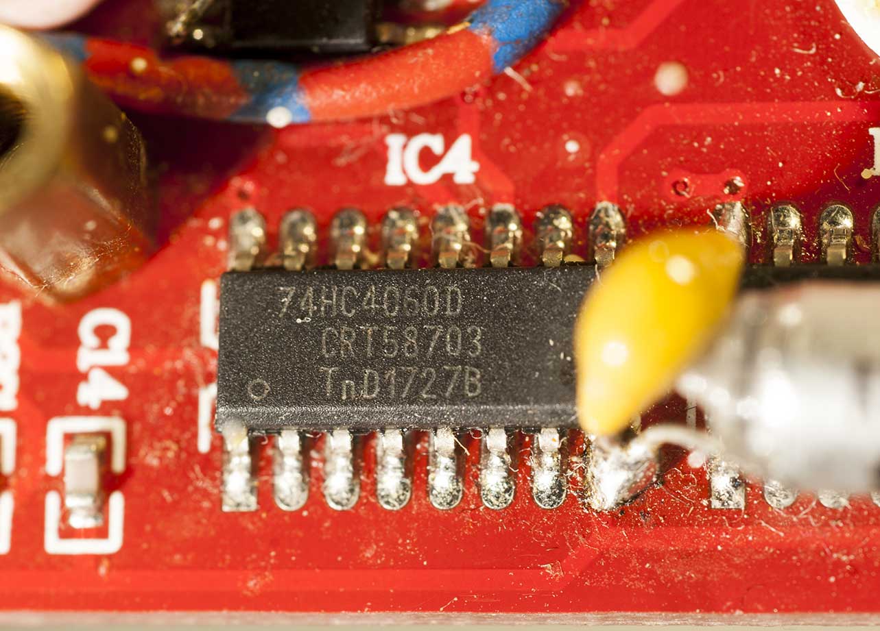
Jörg S. schrieb:
> ob es 2015 schon den Hiland gab

Hallo Jörg,

mein 'Hiland' habe ich Ende 2018 gekauft, das Datum vom Vorteiler IC4
entspricht wohl 27ste Woche 2017. Im Anhang einige Fotos vom Einsatz des
'Hiland'.

Das Hammond Gehäuse macht einen sehr professionellen Eindruck, kann man
das so noch kaufen und hast Du das selbst Beschriftet und die
Durchbrüche/Bohrungen eingebracht. Auf der Hammond-Seite im Netz sehe
ich es leider nicht.

Gruß Horst
Hallo Horst,
hier findest Du es. Es sollte also noch verfügbar sein.
http://www.hammondmfg.com/1553T.htm
Ich hatte es damals bei Digikey gekauft, ist jedoch schon 8 Jahre her.
Die Beschriftung habe ich auf selbstklebende, transparente Etiketten im
A4 Format gedruckt. Die Schablone für die Ausbrüche hatte ich mir damals
als PCB fräsen lassen.

MfG
Jörg

PS.: Im Moment bin ich an einer neuen Version dran, welche über USB-C PD
geladen werden kann und die Daten ebenfalls über diesen USB-Stecker
ausgibt.
Jörg S. schrieb:
> Im Moment bin ich an einer neuen Version dran

...wenn Du schon dabei bist, könntest Du doch auch noch auf ein
grafisches Display umsteigen und einen Drehgeber vorsehen. So
ausgerüstet kannst Du Dir auch mal die Firmware von Markus installieren?

Gruß Horst
Horst O. schrieb:
> ... grafisches Display umsteigen und einen Drehgeber

das mit dem grafischen Display bin ich noch am überlegen, den Drehgeber
finde ich an diesem Gehäuse fehl am Platz.

MfG
Jörg
...der ist aber "leider" super praktisch. Außer man nutzt eh fast
ausschließlich den normalen Test-Mode.

Klaus.
Jörg S. schrieb:
> Drehgeber
> finde ich an diesem Gehäuse fehl am Platz.

... man kann statt dessen "Up Down Key's" benutzen, macht die
Menübedienung einfacher.
Makefile:
# You can also use two separate push-buttons for Up and Down instead ot
the rotary encoder.
# You must set the WITH_ROTARY_SWITCH to 4 for the UP/DOWN push-buttons.

Gruß Horst
Horst O. schrieb:
> ... man kann statt dessen "Up Down Key's" benutzen, macht die
> Menübedienung einfacher.

So mache ich es im Moment auch, funktioniert bestens und passt irgendwie
zum Gerät.

MfG
Jörg
Angehängte Dateien:
-

1_Foto_Adapter_328-644_quartz_top.jpg
210 KB -

2_Foto_Adapter_328-644_quartz_bottom.jpg
230 KB -

3_20230810_223554.jpg
220 KB -

4_20230811_080112.jpg
230 KB -

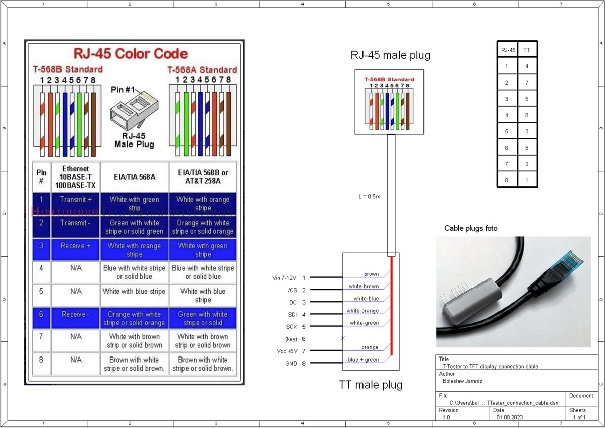
5_Foto_TT-cable_plugs.jpg
210 KB -

6_20230704_124835.jpg
220 KB
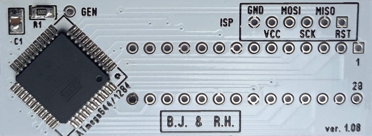
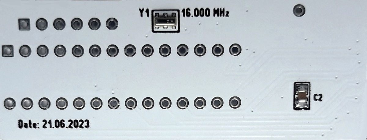
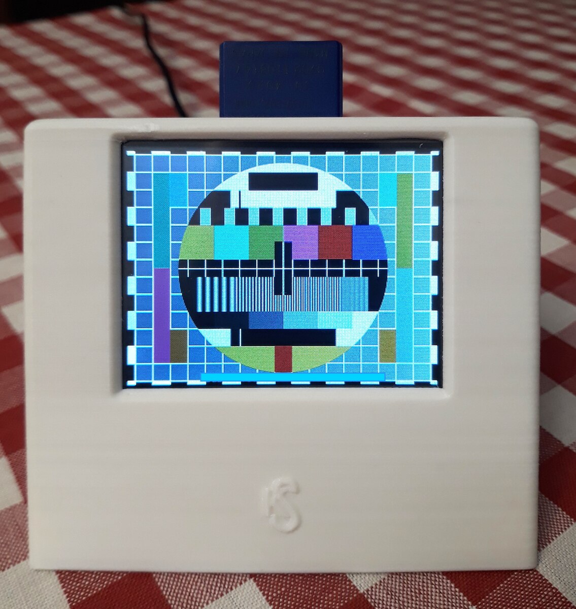
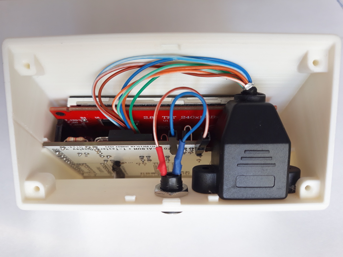
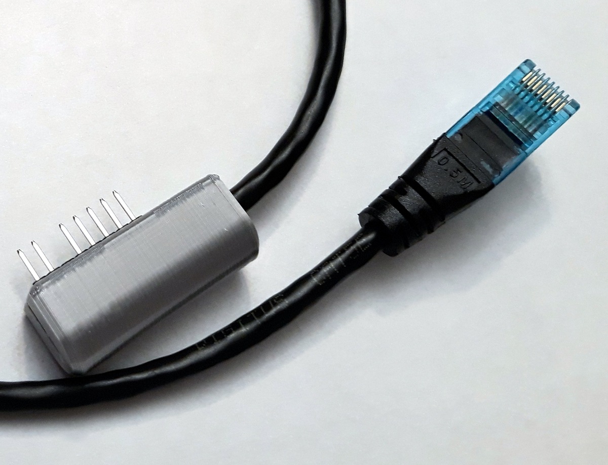
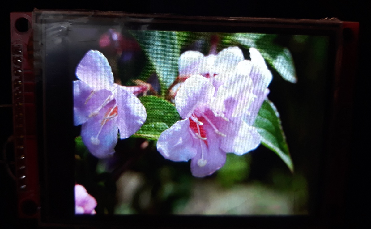
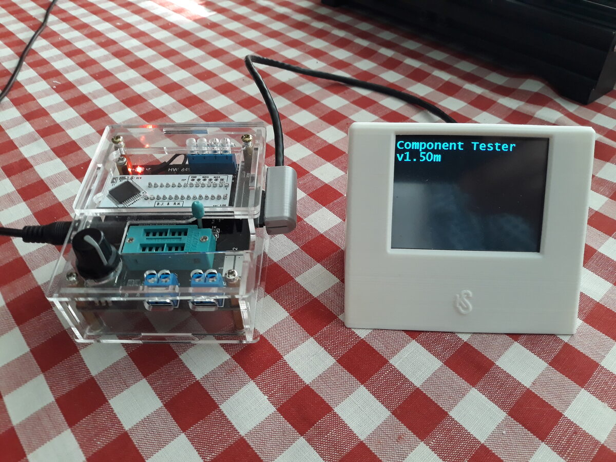
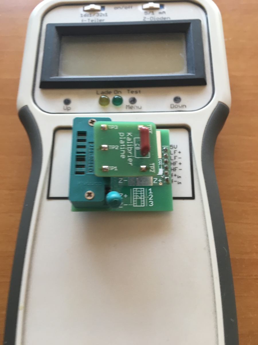
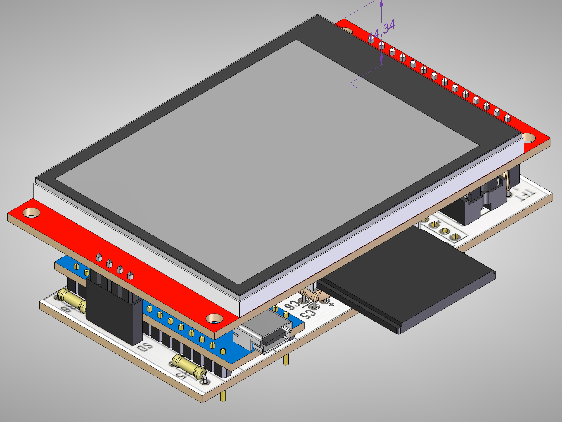
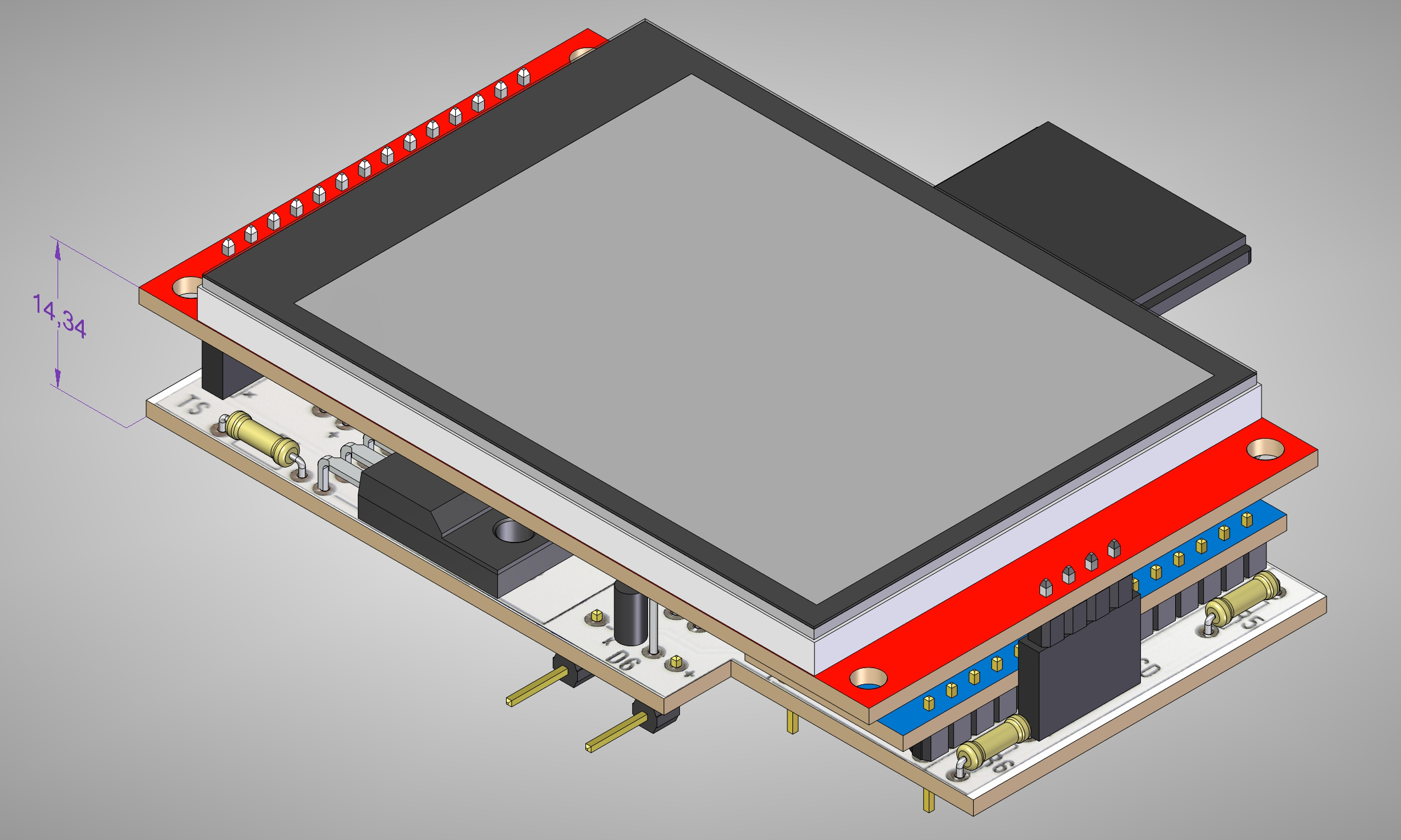
In version 1.08 of the m328/m644 adapter for AY-AT tester I used a 16
MHz SMD quartz crystal, which doubled the data transfer speed to the
display on the SPI bus. Increasing the clock frequency also allows you
to use additional capabilities of the tester, such as increasing the
accuracy of measuring capacitors with a capacity below 100 pF and
checking quartz resonators.

The original 160x128 display, 1.77 inch of the AY-AT tester is too small
and too dark for me. In daylight, you can't see much on it.
I replaced it with a larger and brighter display - TFT 320x240, RGB, 2.8
inch with ST7789 controller.
When designing the interface for the new display, I tried to take full
advantage of its capabilities - also the touch screen and SD card
reader.

The 2.8 inch TFT display with my interface can work:
- in a common, enlarged housing with the AY-AT tester, using the same
8-pin socket as the original display
- in a separate housing, using an additional connection socket (on the
side of the tester) and a cable connecting the tester to the display.
- as a standalone device for displaying a sequence of photos from an SD
card, i.e. Photo-Album. This is where the touch screen comes in handy to
control the display.
...respect! Picture frame might not be a killer feature for a component
tester but SD card might be interesting for reading configs / batch jobs
or saving measurement data or even maybe curve traces? We just wait for
some more weeks and then even tubes are testable ;)

Klaus.
Klaus R. schrieb:
> Wir warten einfach ab
> Noch ein paar Wochen und dann sind sogar Röhren testbar ;)

Hihi   ;-)
Asko B. schrieb:
> Klaus R. schrieb:
>> Wir warten einfach ab
>> Noch ein paar Wochen und dann sind sogar Röhren testbar ;)
>
> Hihi   ;-)

The idea is not as stupid as it looks.
In view of the fashion for retro tube devices, a special adapter for the
T-Tester could measure the amount of electron emission by the cathode of
the lamp. It is possible. However, it is easier to do it in the way
proposed by the authors of the following publication, using a multimeter
and a lamp data sheet:
https://www.bastelnmitelektronik.de/basteleien-ger%C3%A4te-und-schaltungen/basteln-mit-r%C3%B6hren/r%C3%B6hren-%C3%BCberpr%C3%BCfen/
Hallo Markus,
ich möchte mit deiner Software Version einen China Clone reparieren.

Sehe ich das richtig, dass man für das Erzeugen des Binaries sich die
Clones Datei ansieht und alle defines an den richtigen Stellen der
config.h eintragen muss?

Gibt es einen Grund, warum die aktiven #define nicht mit #if !defined()
geklammert sind?
1 | #if !defined(ZENER_R1) |
2 | #define ZENER_R1 180000 |
3 | #endif |
4 | ... |
5 | #if !defined(SW_IR_RECEIVER) && !defined(HW_IR_RECEIVER) |
6 | #define SW_IR_RECEIVER |
7 | #endif |
Mit Klammerung bräuchte man ja bloß den Block aus Clones oben in die
config.h kopieren und wäre fertig.

Ich kann das auch gerne machen und einen PR dazu.
Hi Armin!

Armin J. schrieb:
> Sehe ich das richtig, dass man für das Erzeugen des Binaries sich die
> Clones Datei ansieht und alle defines an den richtigen Stellen der
> config.h eintragen muss?

Aktivieren bzw. anpassen. Und Makefile nicht vergessen!

> Gibt es einen Grund, warum die aktiven #define nicht mit #if !defined()
> geklammert sind?
> ...
> Mit Klammerung bräuchte man ja bloß den Block aus Clones oben in die
> config.h kopieren und wäre fertig.

Die Idee ist, dass sich jeder seine gewünschten Optionen selber
aussucht. Der eine möchte unbedingt den IR-Dekoder, ein anderer
vielleicht etwas anderes.
Markus R. schrieb:
> Die Idee ist, dass sich jeder seine gewünschten Optionen selber
> aussucht. Der eine möchte unbedingt den IR-Dekoder, ein anderer
> vielleicht etwas anderes.

Das verstehe ich, da schadet die Klammerung ja aber nicht, macht es
vielleicht nicht mehr so gut lesbar.

Mit Klammerung kann man vorgefertigte Parametersätze für Clones, was ja
doch häufiger vorkommt, leichter verwalten.
Wärst du bereit, die Klammerung in dein Git Repo aufzunehmen, wenn ich
sie machen würde?

Horst O. schrieb:
> läuft also auf versch. Testern:

Hallo Horst,
wie verwaltest du die Parametersätze für deine Clones?

Gruß
Armin
Armin J. schrieb:
> wie verwaltest du die Parametersätze für deine Clones?

... in Ordnern für TransistorTester und Componententester getrennt und
dann nach Versionsnummer und Gerätekürzel in Unterordnern, z.B.
CT-1.47m_M1284_T7_16MHz oder TT-KH-1_13_M-f_T-TC1-Mod_M644

Gruß Horst
Nochmals eine Frage in die Runde;

lässt sich bei dem Referenzdesign aus der Doku von K.H.Kübbeler auch die
IR-Funktionalität nachrüsten?
Habe ich bis jetzt noch nichts darüber gefunden oder ist dies ein
Alleinstellungsmerkmal von dem M-Tester?

MfG
Jörg
...naja, grdstzl geht doch immer alles - kommt halt auf den Aufwand an.
HW nachrüsten, config file passend einstellen, compilieren, flashen,
fertig.

Klaus.
Jörg S. schrieb:
> auch die
> IR-Funktionalität

... die K-Software für mega644_T7_Mod gibt es, aber keine
IR-Unterstützung. (der T7 und der TC-1 sind m.W. die einzigen Clone mit
integr. IR-Empfänger)

Gruß Horst
Klaus R. schrieb:
> HW nachrüsten, config file

Genau deshalb ja meine Frage, ich habe keinen Schaltplan mit
IR-Unterstützung gefunden oder aber übersehen.
Wenn Du einen Link hättest, der Rest ergibt sich.

MfG
Jörg
Jörg S. schrieb:
> lässt sich bei dem Referenzdesign aus der Doku von K.H.Kübbeler auch die
> IR-Funktionalität nachrüsten?

Bei der m-Firmware gibt es zwei Varianten. Bei der einen wird das
IR-Empfängermodul fest verdrahtet. Und bei der anderen wird das
IR-Empfängermodul einfach an die drei Testpins geklemmt.

> Habe ich bis jetzt noch nichts darüber gefunden oder ist dies ein
> Alleinstellungsmerkmal von dem M-Tester?

Der "M-Tester" ist eine modifizierte Firmware, welche nur ein
IR-Protokoll (NEC) unterstützt.
Armin J. schrieb:
> Das verstehe ich, da schadet die Klammerung ja aber nicht, macht es
> vielleicht nicht mehr so gut lesbar.

Und das dürfte zum Problem werden. Der bisherige Weg hat sich bewährt,
auch wenn er nicht sonderlich anfängerfreundlich ist. Wenn ich das nun
einfach ändern würde, gäbe es garantiert jede Menge Kritik von anderen
Benutzern. Es ist halt einfach so, dass man es nicht allen recht machen
kann. Und deshalb werde ich es auch erst gar nicht versuchen.
Markus R. schrieb:
> Und deshalb werde ich es auch erst gar nicht versuchen.

Never change a running system

Jörg
Kann ich ein bischen verstehen.

Aber die Pro's sollte das ja nicht stören, und die Anfänger werden dabei
ja mitgenommen.
Ausserdem ist es ja dein Code :-).

Schade eigentlich, so muss jeder, so wie Horst, mit verschiedenen Kopien
in verschiedenen Ordnern leben.

Trotzdem Danke
Armin

Jörg S. schrieb:
> Never change a running system

So geht innovation ;-)
Markus R. schrieb:
> Der "M-Tester" ist eine modifizierte Firmware, welche nur ein
> IR-Protokoll (NEC) unterstützt.

Ich meinte mit dem M-Tester einen Tester basierend auf dem
Referenzdesign und der originalen FW von Markus, nicht so einen
China-Klon.

MfG
Jörg

PS. Habe mir jetzt nochmals die Dokumentation von M. Reschke V 1.50
durchgelesen. Dort wird immer nur auf optionale Hardware hingewiesen,
jedoch kein Schaltplan. Vielleicht bin ich auch nur zu blöd.
Armin J. schrieb:
> Mit Klammerung bräuchte man ja bloß den Block aus Clones oben in die
> config.h kopieren und wäre fertig.
> Ich kann das auch gerne machen und einen PR dazu.

Gute Idee! Und wenn der PR nicht akzeptiert wird, mit ein zwei
Mausklicks wird ein fork daraus...
Armin J. schrieb:
> Schade eigentlich, so muss jeder, so wie Horst, mit verschiedenen Kopien
> in verschiedenen Ordnern leben

... ich finde das nicht "Schade", habe 'nen großen Bildschirm und habe
die Ordner übersichtlich vor mir, funktioniert seit Jahren bestens.

Im übrigen ist die Anordnung in den config.h - config_xxxx und Makefile
in der M-Software und in der Makefile in der K-Software ganz
übersichtlich und beides ist hinreichend dokumentiert!

Es gibt Beispiel-Dateien für die verschiedenen Tester-Modelle auf denen
der Neuling hier leicht aufbauen kann.

Gruß Horst
Horst O. schrieb:
> Es gibt Beispiel-Dateien für die verschiedenen Tester-Modelle auf denen
> der Neuling hier leicht aufbauen kann.

Super, wo finde ich die?
Armin J. schrieb:
> Super, wo finde ich die?

... https://github.com/kubi48/TransistorTester-source

Viel Freude beim Ausprobieren.

Gruß Horst
Jörg S. schrieb:
> PS. Habe mir jetzt nochmals die Dokumentation von M. Reschke V 1.50
> durchgelesen. Dort wird immer nur auf optionale Hardware hingewiesen,
> jedoch kein Schaltplan. Vielleicht bin ich auch nur zu blöd.

Für das IR-Empfängermodul braucht es nicht wirklich einen Schaltplan.
Masse, Plus und Daten. Im README ist unter "IR-Empfängermodul an
Testpins" beschrieben, wie das IR-Modul an die Testpins angeschlossen
wird. Zu diversen Hardwareoptionen findest du unter
https://github.com/madires/Transistortester-Warehouse/tree/master/Hardware
Beispiele; und auch in der Doku von Karl-Heinz.
Markus R. schrieb:
> Beispiele; und auch in der Doku von Karl-Heinz.

Diese Dokus habe ich soweit alle durch und die Erweiterungen, welche in
K.H. Doku eingezeichnet sind, sind auch soweit umgesetzt.

Auch der von dir angegeben Link habe ich schon durch. Mir ging es nur
darum, ob es eine Zusammenfassung der 'optionalen Hardwarerweiterungen'
gibt oder ob ich diese jeweils aus den unterschiedlichen Readme's,
Bildern usw. heraussuchen muss.

Wie ich schon weiter oben geschrieben hatte, bin ich gerade dabei, mein
Layout auf den aktuellen Stand zu bringen und da wollte ich halt alle
bis jetzt erhältlichen 'Updates' einfliessen lassen.

Aber so wie es jetzt aussieht, werde ich wohl 2 Tester bauen, einen mit
dem normalen DOGM-Display(k-FW) und eines mit der Grafikversion, incl.
dem IR-Modul und was ich sonst noch so finde mit der m-FW.

MfG
Jörg
Horst O. schrieb:
> Viel Freude beim Ausprobieren.

Das macht keine Freude :-(.
"make all" im Verzeichnis mega328_T3_T4_st7565
1 | F:\Downloads\TransistorTester-source-master\trunk\mega328_T3_T4_st7565>make all |
2 | Das System kann den angegebenen Pfad nicht finden. |
3 | rm -rf ../Obj/mega328_T3_T4_st7565 |
4 | mkdir -p ../Obj/mega328_T3_T4_st7565 |
5 | Syntaxfehler. |
6 | make: *** [objdirect] Error 1 |
make Version ist:
GNU Make 3.82
Built for x86_64-w64-mingw32
Armin J. schrieb:
> Das macht keine Freude

... bei mir läuft das in einer "WinAVR-20100110" Umgebung mit
entsprechender path-Variablen. Die mußt Du bei Dir sicher noch anpassen?

Gruß Horst
Angehängte Dateien:
-

1_display_for_TT_CT.jpg
240 KB -

2_display_for_TT_CT.jpg
220 KB -

3_display_for_TT_CT.jpg
420 KB -

4_display_for_TT_CT.jpg
480 KB -

5_display_for_TT_CT.jpg
360 KB -

6_display_for_TT_CT.jpg
200 KB
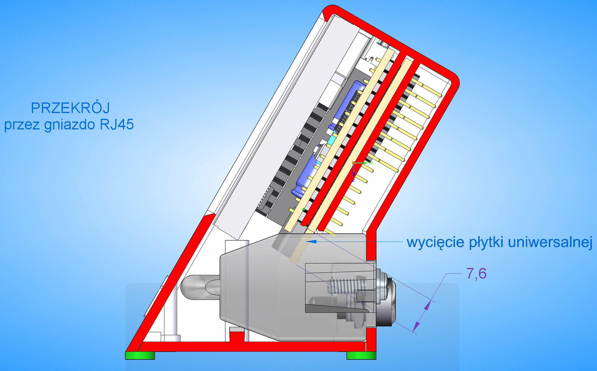
Making a virtual model of graphical display with its interface is very
helpful when designing a display housing for the Transistor/Component
Tester.
Author of the housing design - KS.
Horst O. schrieb:
> ... bei mir läuft das in einer "WinAVR-20100110" Umgebung mit
> entsprechender path-Variablen. Die mußt Du bei Dir sicher noch anpassen?

Das ist angepasst, denn es gibt ja keinen not found sondern einen syntax
Fehler.
Armin J. schrieb:
> Das System kann den angegebenen Pfad nicht finden.

... Du schreibst es doch selber?
Horst O. schrieb:
> Armin J. schrieb:
>> Das System kann den angegebenen Pfad nicht finden.
>
> ... Du schreibst es doch selber?

Und welcher Pfad fehlt denn nun, mal so für Anfänger?
Und der Syntaxerror kommt auch wenn der Pfad nicht stimmt?
"rm" und "make" (und "gcc") findet er ja anstandslos!
Armin J. schrieb:
> rm" und "make" (und "gcc")

... das sind ausführbare Dateien, die beim kompilieren aufgerufen
werden.

bei den älteren Releases der kh-software wurden während des Kompilierens
in die Obj-Ordner eine Art von Kontrolldateien geschrieben z.B.
CheckRotaryEncoder.o und in einen weiteren Unterordner Dep die
zugehörige CheckRotaryEncoder.o.d Datei. Bei den neueren Rev. passiert
das nicht mehr.

Damit wir die gleiche Sprache sprechen, sollten wir zunächst
Betriebssystem, Arbeitsumgebung, und Kompilierwerkzeug abklären?
Horst O. schrieb:
> bei den älteren Releases der kh-software

Komisch, ich wollte eigentlich die m-Software für den TC1 Clone
kompilieren (Windows, Gcc von Arduino) und das erstmal mit T3_T4_st7565
testen.

Nun treffe ich auf komische Fehler und den Hinweis, dass ich wohl die
k-Software am Wickel habe.

Wenn das nicht mal anfängergeeignet ist!

Schade eigentlich.
Armin J. schrieb:
> TC1 Clone

... in den Component-Tester-Verzeichnissen von Markus befindet sich eine
Datei "Clones" mit den Portbelegungen und Einstellungen für übliche
Clones, u. A. auch für TC-1.

Meine Mod am TC-1 u. T7:

Beitrag "Re: Transistortester AVR"

T3_T4_st7565 hat andere Anschlußbelegungen.

Gruß Horst

P.S. ev. im angef. Verz. Drehgeber rausnehmen und M644 gegen M324
tauschen. Hoffentlich hast Du keinen der neuen Fake-TC-1 mit unbekannter
CPU!

Übrigens läuft die K-Software auch auf dem TC-1, auch in Farbe.
Markus R. schrieb:
> Für das IR-Empfängermodul braucht es nicht wirklich einen Schaltplan.
> Masse, Plus und Daten

aber es ist immer empfohlen VCC vom IR Dekoder über 100 Ohm und 4,7µF
Elko anzuschliessen.

https://cdn3.botland.store/img/art/inne/04931_3c.jpg

hat sich bei mir bewährt, ich nehme gerne den TSOP 31236 weil der mit
3,3V und 5V arbeitet und 36kHz mehr mittig liegt als übliche 38kHz TSOP
und man so auch von 30-40 kHz dekodieren kann.
Sehr geholfen hat die LIB von Frank ukw Forumsmoderator.

https://www.mikrocontroller.net/articles/IRMP

Meein Wunsch wäre eine modifizierte Transistortester Version mit dem
ATmega1284p, aber ich bin zu faul oder sagen wir zu alt um das zu bauen.

Sämtliche SW anzupassen und noch TFT LIB für die Grafik.....

Puh ich bin kein Softi
Angehängte Dateien:

Joachim B. schrieb:
> eine modifizierte Transistortester Version mit dem
> ATmega1284p
Hallo Joachim,

gibt es schon als DIY-Version. Ist zwar ein heftiger Drahtverhau, aber
funktioniert sehr gut.
In der Doku von Karl-Heinz ist eine Schaltung mit ATmega644; und im Repo
ist ein 644-DevKit (kicad). Beides kann gerne als Vorlage für einen
Tester mit ATmega644/1284 genommen werden.
Angehängte Dateien:
-

1_FotoAlbum_TT_diagram.jpg
230 KB -

2_Cable_TT.jpg
240 KB -

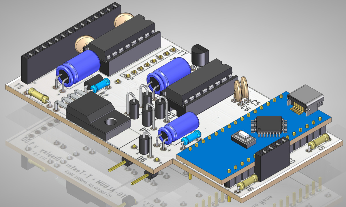
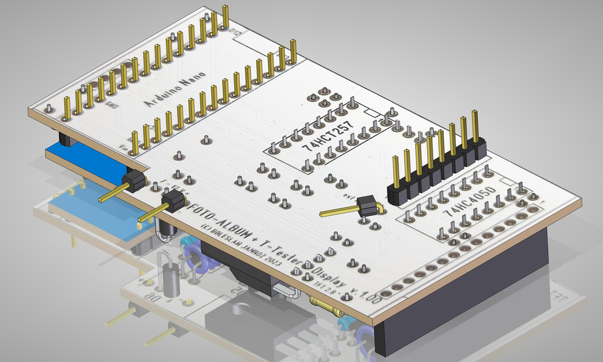
3_Foto_Album_PCB_-_top.jpg
230 KB -

4_Foto_Album_PCB_-_bottom.jpg
240 KB
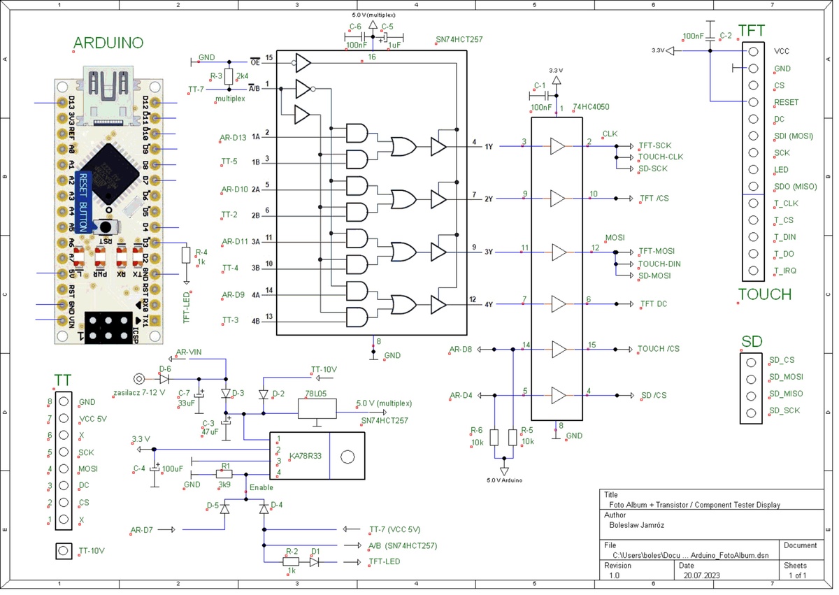

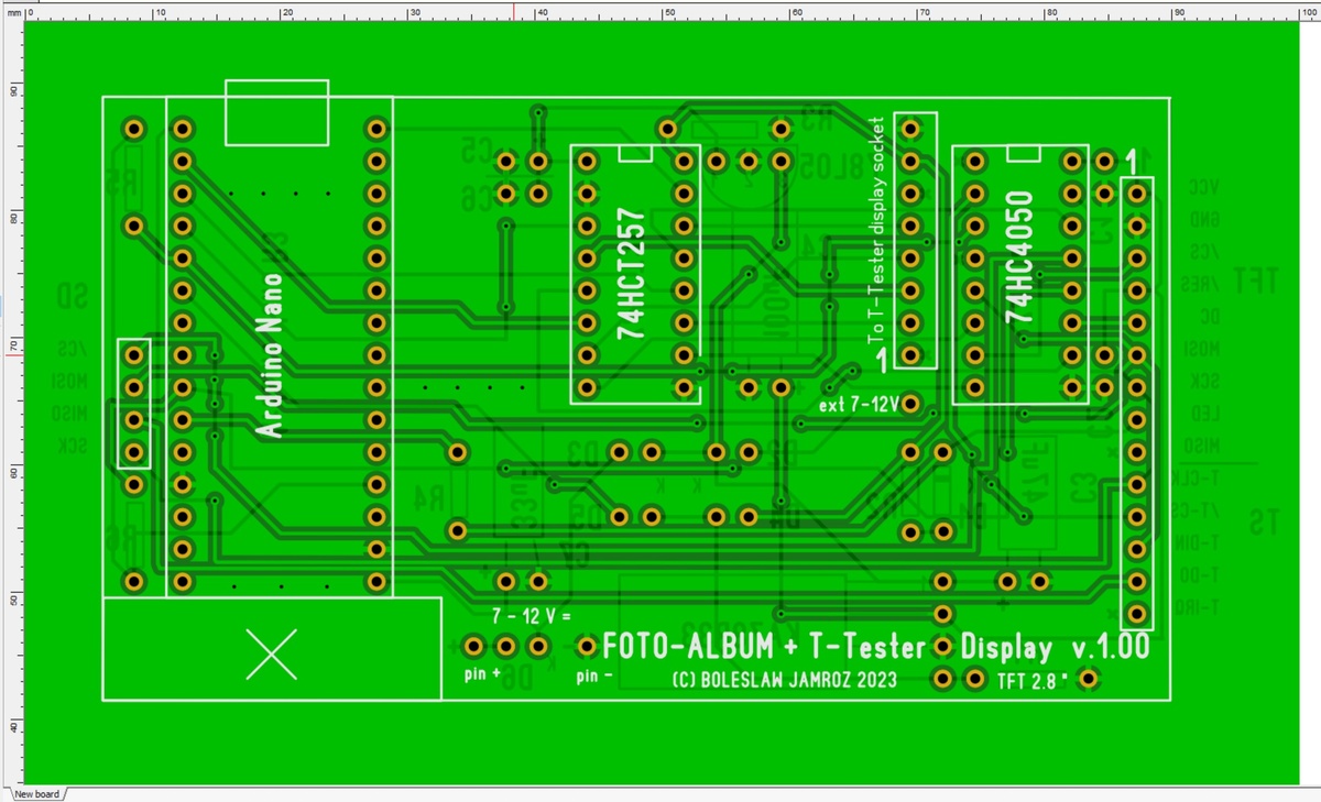
Schematic and PCB of 2.8 inch color TFT display interface for Transistor
/ Component Tester.
The option with Arduino is used to display a sequence of photos from an
SD memory card.
Angehängte Dateien:
-

123.jpg
480 KB
Hi B.
schön das du noch so aktiv bist (an dem Sprint-Layout hast du ja auch
sehr großen Gefallen gefunfen wie ich sehe) aber das wäre mir dann doch
zuviel Aufwand nur um damit Bilder anzusehen, dafür habe ich ein
Smartphone ;-))
ich hatte die Idee mit einem größeren Display auch schon mal und hab da
den Beitrag von Yuriy_K aus dem EEVBLOG Forum gefunden wo er das an den
HILAND-644 angeschlossen hat, leider sehr umständlich mit einer
Adapterplatine. ich hatte dann die original HILAND Platine kopiert,
vergrößert und die Anschlüsse für ein 2.4/2.8" Display sowie einen
fertigen LIPO Lader von Aliexpress vorgesehen (den kann man für das Geld
nicht selber bauen !)
https://www.eevblog.com/forum/testgear/$20-lcr-esr-transistor-checker-project/msg4882043/#msg4882043
https://de.aliexpress.com/item/1005005278905855.html
aber ich hab ja jetzt mein DSO-TC3 mit 2.4" und bin damit eigentlich
ganz zufrieden.
Gruß
R.H.

Thank you for your comment. I owe my progress in using SprintLayout to
your valuable advice in private correspondence.
I used THT technology for the display interface PCB, taking into account
people with poor eyesight who would like to solder the elements on their
own. In addition, there was no need for miniaturization - there was more
than enough room.

I like your PCB design for the Transistor Tester. However, for
controlling the 3.3 volt display lines I would use a different method,
not 10k series resistors.
The cheap Chinese LiPo battery charger you linked to is OK, but... the
battery charger should be able to equalize the voltages on the
individual cells. This charger does not have that capability.

Greetings,
Boleslaw
Hi. B.
bei Aliexpress gibt es dafür kleine PCB´s in zig verschiedenen Größen
und Ausführungen  die sich direkt an die Akkus löten lassen:
https://de.aliexpress.com/item/1005001645794453.html
Wie sollte deiner Meinung nach die Anbindung des Displays denn aussehen
?
Gruß
R. H. schrieb:
> Hi. B.
> bei Aliexpress gibt es dafür kleine PCB´s in zig verschiedenen Größen
> und Ausführungen  die sich direkt an die Akkus löten lassen:
> https://de.aliexpress.com/item/1005001645794453.html
> Wie sollte deiner Meinung nach die Anbindung des Displays denn aussehen
> ?
> Gruß

For two cells, I would choose a charger with a 4.2V (balanced) terminal.

Q:
What do you think the connection of the display should look like?
A:
Same as in tester AY-AT. If the Vcc of the display is 3.3 V and the Vcc
of the controller is 5 V, then the display can be controlled, for
example, by a 74HC4050 chip, powered by 3.3 V.
Angehängte Dateien:
R. H. schrieb:
> hatte dann die original HILAND Platine kopiert

Hallo R. H.,

hast Du von der Platine welche anfertigen lassen und ev. ein Exemplar
für mich zum Verkauf?

Meinen org. Hiland-M644 hab ich schon sehr "verbastelt" und 'ne Version
mit größerem Color-Display fände ich sehr schön.

Gruß Horst
Hello Horst,

Pay attention to the supply voltage of the display on this PCB from R.H.
If you have a display at 3.3 volts on Vcc, that could be a problem,
because that's where the 5 volt power line comes in on the PCB.

Greetings,
Boleslaw
Angehängte Dateien:
If you are interested in the m328/m644 adapter PCB at minimal cost,
please contact me at PM.
Etwas für lange kalte Winterabende:

v1.51m
- Funktion GetThirdProbe() zu Vereinfachungsfunktion UpdateProbes2()
geändert zum Reduzieren der Firmwaregröße incl. Anpassungen der Aufrufe
(Vorschlag von Viktor Klimkovich).
- Optimierung von DataStorage() und ManageAdjustmentStorage(), um
Firmwaregröße zu verringern (Dank an Viktor Klimkovich).
- Option zum Verlangsamen von Bit-Bang-SPI im Falle einer hohen
MCU-Taktfrequenz (SPI_SLOWDOWN, Vorschlag von Viktor Klimkovich).
- Berechnung der Verzögerungsschleife in IR_Detector() geändert, um auch
übertaktete MCUs zu unterstützen (Dank an Viktor Klimkovich).
- Algorithmus für Spannungsabfall in der Funktion LargeCap() verbessert.
- Funktion LargeCap() berücksichtigt nun auch einen negativen
Null-Offset.
- Selbstabgleich gibt nun die Liste der Abgleichwerte nur bei
erfolgreichem Abgleich aus, um Missverständnisse zu vermeiden.
- Fehlerhaften Wert in E24-Tabelle korrigiert (gemeldet von
siealex@EEVblog).
- POWER_OFF_TIMEOUT ist nun auch im Hauptmenü wirksam (Vorschlag von
indman@EEVblog).
- Französische Texte (Dank an moimem@EEVblog).
- Brasilianisch-portugiesische Texte aktualisiert (Dank an
wandows@EEVblog).
- Polnische Texte #2 aktualisiert (Dank an Jacon@EEVblog).
- Zeichen 'q' in font_8x8_iso8859-2_hf.h korrigiert (Dank an
siealex@EEVblog).
- Russische Texte aktualisiert (Dank an indman@EEVblog).
- Spanische Texte aktualisiert (Dank an pepe10000@EEVblog).

Download auf:
-
https://github.com/madires/Transistortester-Warehouse/tree/master/Firmware/m-firmware
- https://github.com/kubi48/TransistorTester-source/tree/master/Markus
(bald)
Markus R. schrieb:
> Download auf: ...

Und im GitHub-Stil auf meinem Repo mit kompletter Entwicklungs-Historie:

https://github.com/Ho-Ro/ComponentTester

Markus R. schrieb:
> Etwas für lange kalte Winterabende:

Die Anpassung für den AY-AT mit 20 MHz-Takt kommt demnächst.
Martin H. schrieb:
> Die Anpassung für den AY-AT mit 20 MHz-Takt kommt demnächst.

https://github.com/Ho-Ro/ComponentTester/tree/AY-AT_20MHz
Wenn man hier nicht ständig und aufmerksam liest, dann ist man völlig
raus.
Bald kann dir das Teil morgens die Brötchen backen.
Wäre hier nicht einmal eine neue Struktur angebracht?
Angehängte Dateien:
-

CT1_51-C0-000-Abgleich_1.jpg
100 KB -

CT1_51-C0-000-Abgleich_2.jpg
190 KB
Hallo Markus,

beim Abgleich kommen bei meinem TC1 "seltsame Werte" bei C0 heraus?
Beim Messen kleiner Kondensatoren wird kein Bauteil gefunden oder
unsinnige Werte zwischen unbelegten Probepins angezeigt.

Gleiches Verhalten übrigens auch bei meiner "Lochraster-Version".

Bei den Vorgänger-Versionen wird hier jeweils ein Wert größer 0
eingetragen und wie üblich getestet.

Gruß Horst
Bitte setze CAP_DISCHARGED auf einen etwas höheren Wert und probiere es
nochmal.
Markus R. schrieb:
> und probiere es
> nochmal.

... habe von 6 auf 10 mV erhöht, ohne Erfolg. C0 weiterhin bei 000!

Gruß Horst

P.S. Im letzten Beitrag von Yuriy_K auf $20 LCR ESR Transistor checker
project von 03:27:12 am rät er dazu, die m1.51 version von cap.h gegen
die aus der m1.50 version zu tauschen - was auch wirklich dieses Problem
beseitigt.
Ja, ist ein Bug. Mit einem kleineren Kondensator kann ich das Problem
reproduzieren. Und bis die Ursache gefunden ist, einfach cap.c von der
1.50m nehmen.
Um das Kondensatorproblem in der 1.51m zu beheben, bitte die Funktion
LargeCap() in der Datei cap.c editieren. Am Anfang von LargeCap()
folgendes einfügen:
1 | int16_t U_temp; /* temporary voltage */ |
Weiter unten den Block
1 | /* consider zero offset */
|
2 | if (U_Cap > U_Zero) /* voltage higher than zero offset */ |
3 | U_Cap -= U_Zero; /* subtract zero offset */ |
4 | else /* shouldn't happen but you never know */ |
5 | U_Cap = 0; /* assume 0V */ |
durch
1 | /* consider zero offset */
|
2 | U_temp = (int16_t)U_Cap; /* explicit type conversion */ |
3 | if (U_temp > U_Zero) /* voltage higher than zero offset */ |
4 | U_temp -= U_Zero; /* subtract zero offset */ |
5 | else /* shouldn't happen but you never know */ |
6 | U_temp = 0; /* assume 0V */ |
7 | U_Cap = (uint16_t)U_temp; /* take result */ |
ersetzen.
Wie kann ich das madires Transistor Projekt über PlatformIO IDE für
VSCode kompilieren.
Gibt es eine Anleitung?
Markus R. schrieb:
> Könntest Du etwas konkreter erklären, was Du mit "neuer Struktur'
> meinst?

Ja klar. Der Grundtyp, den K.H.Kübler noch komplett betreut hatte so
lassen (wenn auch schon sehr lang) und alles was danach kommt, in neue
Beiträge aufteilen.
Karl-Heinz ist noch aktiv. Die letzte Änderung an der k-Firmware war vor
einem Monat. Die Aufteilung in verschiedene Threads macht meiner Meinung
nach nicht viel Sinn, da alles zusammenhängt. Es gibt eine
Grundschaltung mit mehreren Optionen, die alle von k- und m-Firmware
unterstützt werden. Daneben gibt es noch ein paar zusätzliche
Erweiterungen, die bisher nur mit der m-Firmware laufen. Auf der
Softwareseite sieht es sehr ähnlich aus. Wir sehen die zwei
Firmware-Varianten nicht als Konkurrenzprodukte, sondern als
gegenseitige Ergänzung und Inspiration. Viele Benutzer haben ohnehin
beide Varianten laufen. Und vom Support her wäre eine Trennung ebenfalls
schwierig, da nicht nur Fragen zu k/m-Firmware kommen, sondern auch zu
den vielen chinesischen Varianten. Zwei Threads (dieser und der im
EEVblog-Forum) im Auge zu behalten funktioniert ganz gut. Wenn es mehr
wären, würde es auch mehr Arbeit für uns bedeuten. Außerdem ist es so
viel interessanter, d.h. man bekommt mehr mit und sieht was es noch so
gibt.
Hallo Markus,

ich weiß nicht genau, welchen Anteil die HW-Variante AY-AT besitzt. Es
würde deren Benutzer jedoch helfen, schnell etwas funktionierendes zu
konfigurieren, wenn die leicht geänderte Port-Belegung bereits ihren
Niederschlag in config_328.h fände, z.B. so:
1 | diff --git a/config_328.h b/config_328.h
|
2 | index 2acb52f..77fc4a9 100644
|
3 | --- a/config_328.h
|
4 | +++ b/config_328.h
|
5 | @@ -625,7 +625,7 @@
|
6 | * - uses LCD_CS to support rotary encoder in parallel at PD2/3 |
7 | */ |
8 | |
9 | -//#if 0
|
10 | +#if 1
|
11 | #define LCD_ST7565R /* display controller ST7565R */ |
12 | #define LCD_GRAPHIC /* graphic display */ |
13 | #define LCD_SPI /* SPI interface */ |
14 | @@ -668,7 +668,7 @@
|
15 | #define SPI_DDR LCD_DDR /* SPI port data direction register */ |
16 | #define SPI_SCK LCD_SCL /* port pin used for SCK */ |
17 | #define SPI_MOSI LCD_SI /* port pin used for MOSI */ |
18 | -//#endif
|
19 | +#endif
|
20 | |
21 | |
22 | |
23 | @@ -725,6 +725,59 @@
|
24 | |
25 | |
26 | |
27 | +/*
|
28 | + * ST7735 AY-AT
|
29 | + * - 4 wire SPI interface using bit-bang SPI
|
30 | + */
|
31 | +
|
32 | +#if 0
|
33 | +#define LCD_ST7735 /* display controller ST7735 */
|
34 | +#define LCD_GRAPHIC /* graphic display */
|
35 | +#define LCD_COLOR /* color display */
|
36 | +#define LCD_SPI /* SPI interface */
|
37 | +/* control and data lines */
|
38 | +#define LCD_PORT PORTD /* port data register */
|
39 | +#define LCD_DDR DDRD /* port data direction register */
|
40 | +#define LCD_RES PD0 /* port pin used for /RESX (optional) */
|
41 | +#define LCD_CS PD5 /* port pin used for /CSX (optional) */
|
42 | +#define LCD_DC PD1 /* port pin used for D/CX */
|
43 | +#define LCD_SCL PD2 /* port pin used for SCL */
|
44 | +#define LCD_SDA PD3 /* port pin used for SDA */
|
45 | +/* display settings */
|
46 | +#define LCD_DOTS_X 128 /* number of horizontal dots */
|
47 | +#define LCD_DOTS_Y 160 /* number of vertical dots */
|
48 | +//#define LCD_OFFSET_X 4 /* enable x offset of 2 or 4 dots */
|
49 | +//#define LCD_OFFSET_Y 2 /* enable y offset of 1 or 2 dots */
|
50 | +#define LCD_FLIP_X /* enable horizontal flip */
|
51 | +//#define LCD_FLIP_Y /* enable vertical flip */
|
52 | +#define LCD_ROTATE /* switch X and Y (rotate by 90°) */
|
53 | +//#define LCD_BGR /* reverse red and blue color channels */
|
54 | +#define LCD_LATE_ON /* turn on LCD after clearing it */
|
55 | +/* font and symbols: horizontally aligned & flipped */
|
56 | +#define FONT_10X16_HF /* 10x16 font */
|
57 | +//#define FONT_6X8_ISO8859_2_HF /* 6x8 Central European font */
|
58 | +//#define FONT_8X8_ISO8859_2_HF /* 8x8 Central European font */
|
59 | +//#define FONT_8X12T_ISO8859_2_HF /* thin 8x12 Central European font */
|
60 | +//#define FONT_8X16_ISO8859_2_HF /* 8x16 Central European font */
|
61 | +//#define FONT_10X16_ISO8859_2_HF /* 10x16 Central European font */
|
62 | +//#define FONT_8X16_WIN1251_HF /* 8x16 cyrillic font */
|
63 | +//#define FONT_8X16ALT_WIN1251_HF /* 8x16 alternative cyrillic font */
|
64 | +#define SYMBOLS_30X32_HF /* 30x32 symbols */
|
65 | +//#define SYMBOLS_30X32_ALT1_HF /* 30x32 alternative symbols #1 */
|
66 | +//#define SYMBOLS_30X32_ALT2_HF /* 30x32 alternative symbols #2 */
|
67 | +//#define SYMBOLS_32X32_HF /* 32x32 symbols */
|
68 | +//#define SYMBOLS_32X32_ALT1_HF /* 32x32 alternative symbols #1 */
|
69 | +//#define SYMBOLS_32X32_ALT2_HF /* 32x32 alternative symbols #2 */
|
70 | +/* SPI bus */
|
71 | +#define SPI_BITBANG /* bit-bang SPI */
|
72 | +#define SPI_PORT LCD_PORT /* SPI port data register */
|
73 | +#define SPI_DDR LCD_DDR /* SPI port data direction register */
|
74 | +#define SPI_SCK LCD_SCL /* port pin used for SCK */
|
75 | +#define SPI_MOSI LCD_SDA /* port pin used for MOSI */
|
76 | +#endif
|
77 | +
|
78 | +
|
79 | +
|
80 | /* |
81 | * ST7920 |
82 | * - SPI interface using bit-bang SPI |
83 | @@ -944,11 +997,26 @@
|
84 | * rotary encoder |
85 | */ |
86 | |
87 | +#if 1
|
88 | #define ENCODER_PORT PORTD /* port data register */ |
89 | #define ENCODER_DDR DDRD /* port data direction register */ |
90 | #define ENCODER_PIN PIND /* port input pins register */ |
91 | #define ENCODER_A PD3 /* rotary encoder A signal */ |
92 | #define ENCODER_B PD2 /* rotary encoder B signal */ |
93 | +#endif
|
94 | +
|
95 | +
|
96 | +/*
|
97 | + * rotary encoder AY-AT
|
98 | + */
|
99 | +
|
100 | +#if 0
|
101 | +#define ENCODER_PORT PORTD /* port data register */
|
102 | +#define ENCODER_DDR DDRD /* port data direction register */
|
103 | +#define ENCODER_PIN PIND /* port input pins register */
|
104 | +#define ENCODER_A PD3 /* rotary encoder A signal */
|
105 | +#define ENCODER_B PD1 /* rotary encoder B signal */
|
106 | +#endif
|
107 | |
108 | |
109 | /* |
Danke für Deine kontinuierliche Verbesserung unseres
Lieblingsspielzeugs.

Martin
Hi Martin!

Die notwendigen Einstellungen für den AY-AT/GM328A findest Du in der
Datei "Clones" (auch für viele andere). Dort finden sich auch Hinweise
zu verschiedenen Modellvarianten des jeweiligen Testers. Beim
AY-AT/GM328A gibt es z.B. zwei unterschiedliche Displays.

ciao,
 Markus
Markus R. schrieb:
> Die notwendigen Einstellungen für den AY-AT/GM328A findest Du in der
> Datei "Clones"

Ich weiß - und habe meine AY-AT.diff, damit läuft ein Update nahezu
automatisch.
Ich dachte eher an die nicht so tief in der Materie steckenden Nutzer,
die statt "#if 1" oder "#if 0" einzutragen sich Codeschnipsel
zusammensuchen müssen.
Markus R. schrieb:
> Und vom Support her wäre eine Trennung ebenfalls
> schwierig

Da hast du natürlich recht. Ich hätte jetzt auch keine konkrete,
wirklich gute Idee.
Martin H. schrieb:
> Ich weiß - und habe meine AY-AT.diff, damit läuft ein Update nahezu
> automatisch.
> Ich dachte eher an die nicht so tief in der Materie steckenden Nutzer,
> die statt "#if 1" oder "#if 0" einzutragen sich Codeschnipsel
> zusammensuchen müssen.

Wie wäre es mit Firmware-Paketen für verschiedene Clone? Also Makefile,
config.h, config_<MCU>.h und übersetzte Firmware als zip oder tgz. Dazu
könnte ich ein git-Repo einrichten und allen, die mitmachen wollen,
Schreibrechte geben.
Markus,

gute Idee, alles an einem Ort. Meine Anpassung für AY-AT mit 20 MHz
pflege sich in meinem Repo im Branch AY-AT_20MHz:
https://github.com/Ho-Ro/ComponentTester/tree/AY-AT_20MHz .
Meine Änderungen betreffen neben Makefile, config.h und config_328.h
auch inductor.c, dort finden sich indman's Anpassungen für 20 MHz, die
er auf auf eevblog veröffentlicht hat. Ich würde das noch abhängig vom
CPU-Takt über "#if F_CPU > xxx" kapseln.

Martin
Hallo, mal eine Frage zur Konfiguration.

HW: Atmega 644PA mit DOGM204 (Text) oder DOGM128 (Grafik)
SW: 1.12K und 1.13K

Die Ansteuerung des Displays erfolgt per I²C für das DOGM204 auf PCO und
PC1 als Ports.

Für die Ansteuerung des DOGM128 per SPI ebenfalls über PC0, PC1 und
zusätzlich PC2 für das RS Signal.

Diese Konfigurationsänderungen sind in der config.h eingetragen und
funktionieren auch.
-------------
Nun meine Frage:
Wie setze ich diese Ansteuerung des DOGM128 (ST7565 Kontroller) mit der
Software 1.50 von Hr. Reschke um, also Anbindung per SPI über PC0 (CLK),
PC1 (SI) und PC2 (A0).
Die Änderungen sollten in der config_644.h Datei erfolgen?
Wo finde ich die Zuordung zwischen den SPI-Signalen und den
Displayanschlüssen?

Ich habe mal das Datenblatt angefügt. Falls es gegen irgend welche
Vorschriften verstößt, bitte löschen.

MfG
Jörg
Habe mal die Konfig üfr bit-bang SPI angehängt.

Der Knackpunkt war die #define SPI_BITBANG Direktive, hatte als mit
SPI_Hardware probiert, dummer Fehler.
1 | /*
|
2 | * ST7565R
|
3 | * - SPI interface using bit-bang SPI
|
4 | * - with same pins as hardware I2C
|
5 | * - settings for Electronic Assembly EA DOGM/DOGL128-6
|
6 | */
|
7 | |
8 | #if 1
|
9 | #define LCD_ST7565R /* display controller ST7565R */ |
10 | #define LCD_GRAPHIC /* graphic display */ |
11 | #define LCD_SPI /* SPI interface */ |
12 | /* control and data lines */
|
13 | #define LCD_PORT PORTC /* port data register */ |
14 | #define LCD_DDR DDRC /* port data direction register */ |
15 | #define LCD_RESET PB2 /* port pin used for /RES (optional) */ |
16 | #define LCD_CS PB6 /* port pin used for /CS1 (optional) */ |
17 | #define LCD_A0 PC2 /* port pin used for A0 */ |
18 | #define LCD_SCL PC0 /* port pin used for SCL */ |
19 | #define LCD_SI PC1 /* port pin used for SI (data input) */ |
20 | /* display settings */
|
21 | #define LCD_DOTS_X 128 /* number of horizontal dots */ |
22 | #define LCD_DOTS_Y 64 /* number of vertical dots */ |
23 | #define LCD_OFFSET_X 4 /* enable x offset of 4 dots */ |
24 | #define LCD_FLIP_X /* enable horizontal flip */ |
25 | //#define LCD_FLIP_Y /* enable vertical flip */
|
26 | #define LCD_START_Y 0 /* start line (0-63) */ |
27 | #define LCD_CONTRAST 25 /* default contrast (0-63) */ |
28 | //#define LCD_LONG_RESET /* long reset for NT7538 */
|
29 | /* font and symbols: vertically aligned & flipped, bank-wise grouping */
|
30 | //#define FONT_6X8_VF /* 6x8 font */
|
31 | #define FONT_8X8_VF /* 8x8 font */ |
32 | //#define FONT_8X16_VFP /* 8x16 font */
|
33 | //#define FONT_6X8_ISO8859_2_VF /* 6x8 Central European font */
|
34 | //#define FONT_8X8_ISO8859_2_VF /* 8x8 Central European font */
|
35 | //#define FONT_8X12T_ISO8859_2_VFP /* thin 8x12 Central European font */
|
36 | //#define FONT_8X16_ISO8859_2_VFP /* 8x16 Central European font */
|
37 | //#define FONT_8X8_WIN1251_VF /* 8x8 cyrillic font */
|
38 | //#define FONT_8X8ALT_WIN1251_VF /* 8x8 alternative cyrillic font */
|
39 | //#define FONT_8X8T_WIN1251_VF /* thin 8x8 cyrillic font */
|
40 | //#define FONT_8X12T_WIN1251_VFP /* thin 9x12 cyrillic font */
|
41 | //#define FONT_8X16_WIN1251_VFP /* 8x16 cyrillic font */
|
42 | #define SYMBOLS_24X24_VFP /* 24x24 symbols */ |
43 | //#define SYMBOLS_24X24_ALT1_VFP /* 24x24 alternative symbols #1 */
|
44 | //#define SYMBOLS_24X24_ALT2_VFP /* 24x24 alternative symbols #2 */
|
45 | /* SPI bus */
|
46 | #define SPI_BITBANG /* bit-bang SPI */ |
47 | #define SPI_9 /* support 9 bit frames */ |
48 | #define SPI_PORT LCD_PORT /* SPI port data register */ |
49 | #define SPI_DDR LCD_DDR /* SPI port data direction register */ |
50 | #define SPI_SCK LCD_SCL /* port pin used for SCK */ |
51 | #define SPI_MOSI LCD_SI /* port pin used for MOSI */ |
52 | #endif
|
[Mod: C-Tags repariert]
Jörg S. schrieb:1 | #define LCD_ST7565R /* display controller ST7565R */ |
2 | /* control and data lines */
|
3 | #define LCD_PORT PORTC /* port data register */ |
4 | #define LCD_DDR DDRC /* port data direction register */ |
5 | #define LCD_RESET PB2 /* port pin used for /RES (optional) */ |
6 | #define LCD_CS PB6 /* port pin used for /CS1 (optional) */ |
Der ST7565-Treiber unterstützt keinen separaten Port für /Reset oder
/CS, d.h. alle Signale müssen auf einem Port liegen. Es sollte aber
nicht schwer sein, den Treiber entsprechend zu modifizieren.
Hallo Markus,
besten Dank für die Rückmeldung. Die beiden optionlen Pins habe ich nur
nicht auskommentiert.
Sinn und Zweck der Übung ist, auf einer Platine sowohl das DOGM204
(text) als auch das DOGM128 (grafik) einsetzen zu können. Siehe
folgenden Link mit ein paar Fotos.
Beitrag "Re: Transistortester AVR"

Auf das Board mit dem Textdisplay die Version 1.13K mit dem ganzen
Frequenzzeugs, auf das Grafikboard deine Version 1.51M mit dem Rest, wie
feste IR, Drehgeber usw, was so alles an Aufrüstung zu haben ist. Zum
Glück hatte ich mich vor gut 10 Jahren schon für den Atmega644
entschieden, jedoch auch schon einen 1284 auf Lager.

Ich wünsche allen ein gutes neues Jahr.

MfG
Jörg
Boleslaw J. schrieb:
> Attached are modified files for ComponentTester version 1.50m for
> m328-m644 (AY-AT) adapter.
Can you provide a compiled version of the source code?

Which Crystal was used 8 or 16 MHz?

Which FUSES must be used?
FUSES for ATmega644p:
L:0xF7
H:0xD9
E:0xFC
Yes, I can.
The compiled version is for ATmega 644p, 16 MHz resonator and fuses:
L:0xF7, H:0xD9, E:0xFC.
Boleslaw J. schrieb:
> Yes, I can.
> The compiled version is for ATmega 644p, 16 MHz resonator and fuses:
> L:0xF7, H:0xD9, E:0xFC.

Thanks for the binary code. However, the display only shows white after
switching on. I use the original display from the HW-849A device.
That would have to be a 1.77 inch, 160x128 display with ST7735
controller.

Do you know the problem?
Alois N. schrieb:
> Thanks for the binary code. However, the display only shows white after
> switching on. I use the original display from the HW-849A device.
> That would have to be a 1.77 inch, 160x128 display with ST7735
> controller.
>
> Do you know the problem?

Yes, I know this problem. For this reason, the author of the program
includes the source files of the program, thus giving the user the
opportunity to adapt it to his hardware configuration, functionality and
interface language.

My display is a color graphic display with a diagonal of 2.8",
320x240px, ST7789.
For such a display I included binaries in the English version in the
previous post.

Now I'm attaching the binaries in the English version compiled for your
display (I checked them in the component tester).
Hello Boleslaw,

Have you already adapted the IR extensions for the new firmware m 1.51?

Greetings Horst
Boleslaw J. schrieb:
> Alois N. schrieb:
>> Thanks for the binary code. However, the display only shows white after
>> switching on. I use the original display from the HW-849A device.
>> That would have to be a 1.77 inch, 160x128 display with ST7735
>> controller.
>>
> Now I'm attaching the binaries in the English version compiled for your
> display (I checked them in the component tester).
Thank you. It works fine.
Horst O. schrieb:
> Hello Boleslaw,
> Have you already adapted the IR extensions for the new firmware m 1.51?
> Greetings Horst

I'm working on it.
Greetings
Boleslaw
Angehängte Dateien:
-

20240205_231137.jpg
230 KB -

20240205_231248.jpg
230 KB -

20240205_232933.jpg
240 KB
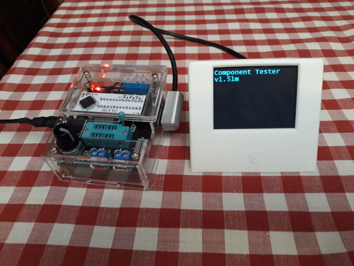
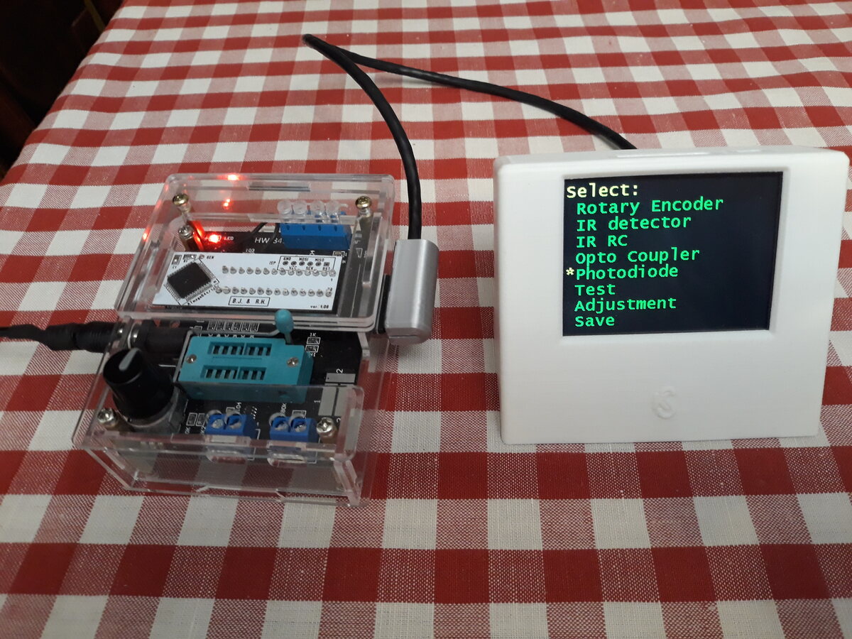
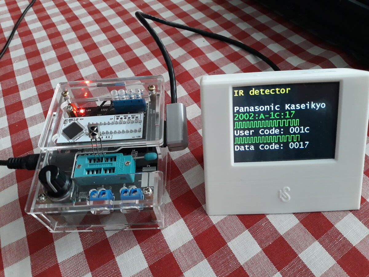
Attached are modified files for ComponentTester version 1.51m for
m328-m644 (AY-AT) adapter.
Wo kann ich Fehler in der m-Firmware melden? Hier ist einer:
Die I2C_HARDWARE-Implementierung von I2C_ReadByte setzt I2C.Byte nicht.
Patch für 1.51m anbei.
Danke für die Fehlermeldung! Der einfachste und direkteste Weg wäre per
EMail (Adresse im README). Ansonsten hier im Thread oder im
EEVblog-Forum.
Ah, danke! Keine Ahnung, warum ich die Adresse im README nicht fand.
Hier ist noch ein Fehler (oder Unverständnis meinerseits), aber ohne
Patch weil ich in meinem Code für den FT6336 (an einem Display mit
ST7789) die Kalibrierung ganz weggelassen habe, da nicht nötig:

Die Touch-Kalbrierung funktioniert nicht, wenn sie, wie von main aus,
mit 0 für Touch.X_Start und Touch.X_Stop aufgerufen wird. Denn dann
berechnet Touch_CharPos die Zeichenkoordinaten immer zu (1,1), die
Kalibrierung für den zweiten Punkt kann also niemals erfolgreich
abgeschlossen werden. Was habe ich übersehen?
Und noch ein Problem, teilweise durch mich verursacht: Ich baute meinen
Tester mit einem ATmega2560, da bleiben einige Pins unbenutzt. Da ich
mir spätere Erweiterungen offen halten wollte, habe ich die nicht extern
beschaltet. Die Folge war, daß die Stromaufnahme des ATmega2560 bei
(WIMRE) 80 mA bis 100 mA lag, also viel zu hoch. Dies am Anfang von main
half:

  /* Enable pull ups on most pins to avoid undefined voltage on inputs
*/
  PORTA = ~((1 << IR_DATA) | (1 << BUZZER_CTRL));
  PORTB = ~(1 << SIGNAL_OUT);
  PORTC = 0xff;
  PORTD = 0xff;
  PORTE = 0xff;
  PORTF = 0xff;
  PORTG = ~(1 << BOOST_CTRL);
  PORTH = 0xff;
  PORTJ = 0xff;
  PORTK = 0xff;
  PORTL = 0xff;

Hängt aber natürlich von der Konfiguration ab. Ich bin zu faul, das zu
verallgemeinern, deshalb kein Patch.
F. P. schrieb:
> Die Touch-Kalbrierung funktioniert nicht, wenn sie, wie von main aus,
> mit 0 für Touch.X_Start und Touch.X_Stop aufgerufen wird. Denn dann
> berechnet Touch_CharPos die Zeichenkoordinaten immer zu (1,1), die
> Kalibrierung für den zweiten Punkt kann also niemals erfolgreich
> abgeschlossen werden. Was habe ich übersehen?

Der Defaultwert für Touch.X_Start und Touch.X_Stop ist Null, solange
kein Abgleich erfolgt ist und im EEPROM abgespeichert wurde. So wird
erkannt ob ein Abgleich notwendig ist.

Wenn es beim Abgleich Probleme gibt, kann das an der Orientierung oder
der Verdrahtung des Touchscreens liegen. Evtl. muss TOUCH_FLIP_X,
TOUCH_FLIP_Y oder TOUCH_ROTATE aktiviert werden. Das ist im README unter
"Touch-Screen" erklärt. Schaue dir die angezeigten Rohwerte (0-4095)
beim Abgleich an. Es kann auch möglich sein, dass die Kommunikation mit
dem Touch-Controller ein Problem hat.
Ah, ich sehe gerade, daß Touch_AdjustPos bei den ersten zwei Durhläufen
1 statt 2 zurückgeben darf (und beim ersten Durchlauf immer nur 1
liefert, wenn zuvor nicht kalibiriert wurde).
Anderes Problem: wait40us in IR_Detector dauert bei mir zu lange,
_delay_us(40) geht aber, also wie SW_IR_TX_ALTDELAY beim Senden. D.h.
ich brauche SW_IR_RX_ALTDELAY. Vorerst ist _delay_us(40) fest eingebaut.
DataStorage mit Mode=STORAGE_LOAD gibt n zurück, obwohl es in diesem
Fall nicht initialisiert wurde.
Ein Tippfehler in der Doku von UI_AUTOHOLD (continous statt continuous)
hat mich einige Zeit gekostet, als ich versuchte, durch Suche nach
"continuous" herauszufinden, wie ich den continuous mode abschalten
kann.
Eine Stelle in config_1280.h ist verwirrend wegen C vs. D:
1 | #define LC_CTRL_PORT PORTD /* port data register */ |
2 | #define LC_CTRL_DDR DDRD /* port data direction register */ |
3 | #define LC_CTRL_CP PC4 /* reference cap (low: on / high: off) */ |
4 | #define LC_CTRL_LC PC5 /* L/C selection (low: C / high: L */ |
Da PC4==PD4 und PC5==PD5 macht das dem Code nichts aus, aber jemand, der
nicht genau hinschaut, könnte die Hardware falsch bauen.
F. P. schrieb:
> Anderes Problem: wait40us in IR_Detector dauert bei mir zu lange,
> _delay_us(40) geht aber, also wie SW_IR_TX_ALTDELAY beim Senden. D.h.
> ich brauche SW_IR_RX_ALTDELAY. Vorerst ist _delay_us(40) fest eingebaut.

Interessant! Du bist der Erste mit einem solchen Problem.

F. P. schrieb:
> DataStorage mit Mode=STORAGE_LOAD gibt n zurück, obwohl es in
> diesem Fall nicht initialisiert wurde.

Das ist so gewollt. DataStorage() liest bzw. schreibt die Abgleichsdaten
und kümmert sich auch um die Prüfsumme. Der Werte selber sind hier
unwichtig.

F. P. schrieb:
> Ein Tippfehler in der Doku von UI_AUTOHOLD (continous statt continuous)
> hat mich einige Zeit gekostet, als ich versuchte, durch Suche nach
> "continuous" herauszufinden, wie ich den continuous mode abschalten
> kann.

Ist bekannt; wurde bereits korrigiert.

F. P. schrieb:
> Eine Stelle in config_1280.h ist verwirrend wegen C vs. D:

Danke für den Hinweis!
Bitte OM's, entschuldigt bitte, ich hab hier nicht alles gelesen:

Ich nehme das geniale Gerät als Transistorprüfer bem
Basteln zur Auswahl von Transistorpärchen und zum Feststellen
der Anschlußbeinchen.
Nun meine Frage:
Kann das Gerätchen auch bei Leistungstransistoren
die Stromverstärkung messen?
Naja, messen kann es dies, aber sind die Meßwerte
auch bei Leistungstransis brauchbar?

mfg
Der hFE-Wert zeigt die Verstärkung im Kleinsignalbereich (wegen dem
begrenzten Teststrom). Für einen aussagefähigen Wert bei
Leistungstransistoren müsste man mit entsprechend hohen Strömen messen,
wie sie in der jeweiligen Applikation vorkommen. Schaue dir am besten
ein paar Datenblätter von Leistungstransistoren an, insbesondere das
Diagramm hFE-I_C.
Markus R. schrieb:
> Der hFE-Wert zeigt die Verstärkung im Kleinsignalbereich (wegen dem
> begrenzten Teststrom). Für einen aussagefähigen Wert bei
> Leistungstransistoren müsste man mit entsprechend hohen Strömen messen,
> wie sie in der jeweiligen Applikation vorkommen. Schaue dir am besten
> ein paar Datenblätter von Leistungstransistoren an, insbesondere das
> Diagramm hFE-I_C.

OK, sowas hab ich mir fast gedacht, da muß ich die Teile
dann doch mit unserem großen Prüfer einmessen zur Hochzeit
in nem Marantz Verstärker.

Ich danke Euch für die Entwicklung dieses feinen Gerätes,
das gerad uns Bastlern, die öfter ihre Transis aus dem
"Schuhkarton" greifen, genial hilft.

mfg
Lotta.
Hallo zusammen,

kennt jemand eine zuverlässige Quelle für einen LCR-T7, der einen ATmega
drin hat und keinen China-ARM-Prozessor?

Vielen Dank.

Gruß, Thorsten
Angehängte Dateien:
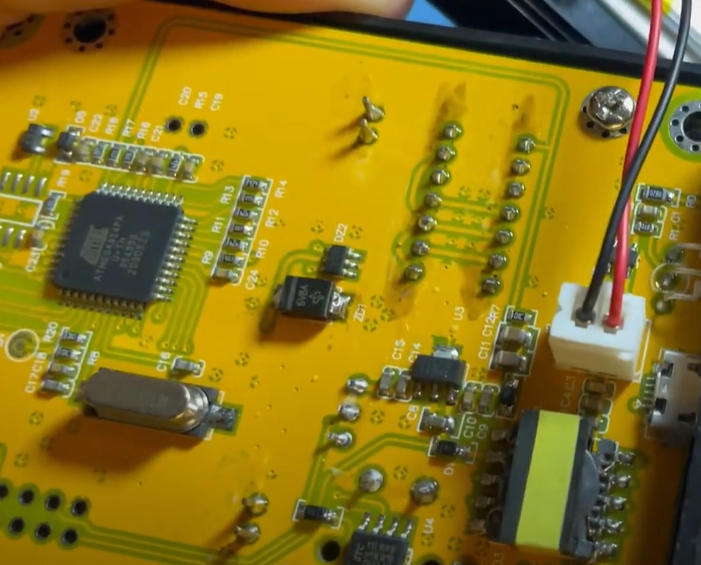
I seen this one, Look's Real

https://joy-it.net/en/products/JT-LCR-T7

https://www.youtube.com/watch?v=uwW3ewRs0Tk&t=168s
Thanks for the reply.
Unfortunately Joy-It currently also seems to use the "new" design with
that Chinese-ARM-MCU. I have exactly this Joy-It LCR-T7 (because I read,
that this should use the ATmega, but it does not...).

Regards, Thorsten
Thorsten schrieb:
> Beitrag melden Bearbeiten Löschen Markierten Text zitieren Antwort
> Antwort mit Zitat

Thanks for sharing, the Warning. China trickery.
Angehängte Dateien:
-

WIN_20240310_12_50_23_Pro.jpg
120 KB -

WIN_20240310_12_45_07_Pro.jpg
150 KB -

WIN_20240310_13_26_25_Pro.jpg
140 KB -

Eagle-Cad.png
18 KB -

KiCAD-CNC-Milling.png
71 KB
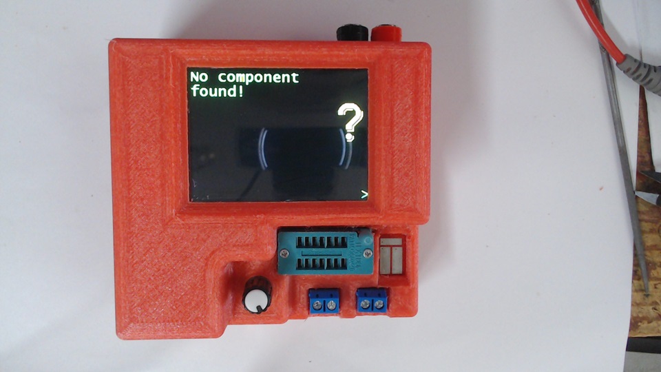
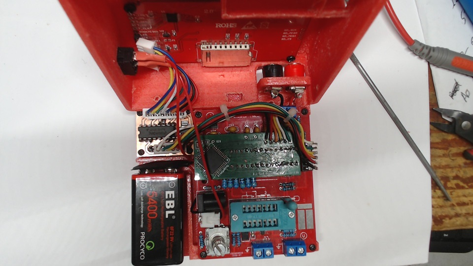
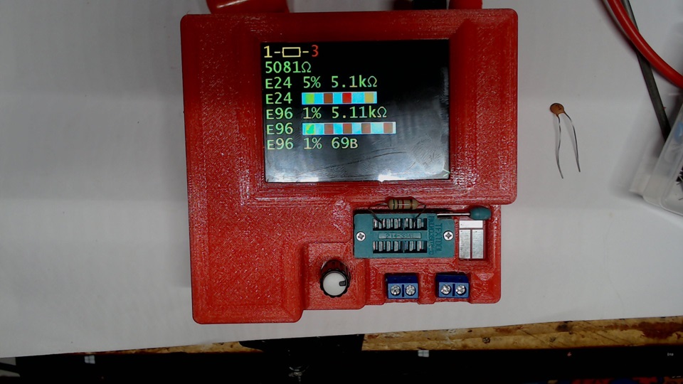
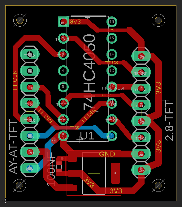
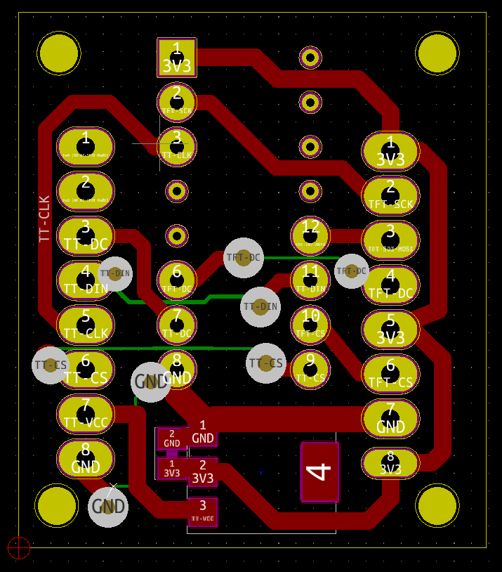
Finished doing the Adapter_m328_m644_AY-AT ComponentTester
Thanks to von Boleslaw J.,von Markus R. and all who made it possible.
I used KiCAD to make possible to CNC mill TFT Adapter and make traces
larger.
Diese gelben T4 kommen immer mit losem Display.
Gibt es einen Grund dafür?
Mit ein bisschen Heißkleber ist das schnell erledigt, aber blöd ist das
trotzdem.
Habe gerade drei Stück bekommen. Schon beim Abziehen der Folie hätte ich
fast das Display abgerissen.
Mine also came loose while in the plex-glass case. I used thin double
sided tape to hold it. It must be the nature of the display and fast
production. Nothing you can do.
Angehängte Dateien:
-

Stray_Error_-_PN2.png
340 KB
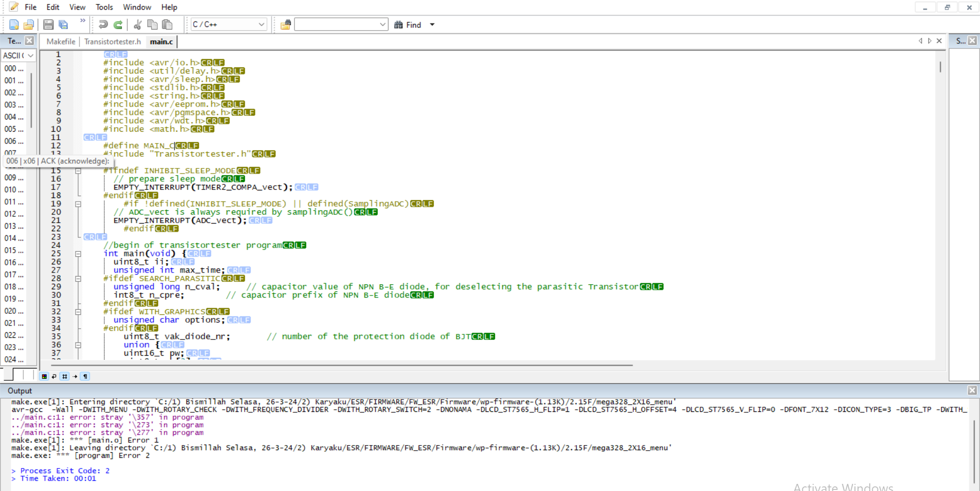
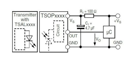
Hallo Sir,,,
ich würde gerne fragen, wie man diese Art von Fehler beheben kann ?
Ich danke Ihnen im Voraus und
wünsche Ihnen immer gute Gesundheit :D
1 | ../main.c:1: error: stray '\357' in program |
2 | ../main.c:1: error: stray '\273' in program |
3 | ../main.c:1: error: stray '\277' in program |
4 | make.exe[1]: *** [main.o] Error 1 |
5 | make.exe[1]: Leaving directory `MY DIRECTORY' |
6 | make.exe: *** [program] Error 2 |
7 | |
8 | > Process Exit Code: 2 |
9 | > Time Taken: 00:01 |
Da sind ein paar ungewöhnliche Zeichen in den Sourcecode geraten (copy &
paste, nationale Zeichen). Es kann sein, dass der Editor diese nicht
anzeigt. Anderen Editor nehmen oder die Zeile einfach überschreiben.

PS: Die Zeichen sind oktal angegeben.
Bitte melde dich an um einen Beitrag zu schreiben. Anmeldung ist kostenlos und dauert nur eine Minute.
Bestehender Account
Schon ein Account bei Google/GoogleMail? Keine Anmeldung erforderlich!
Mit Google-Account einloggen
Mit Google-Account einloggen
Noch kein Account? Hier anmelden.